If you need to weld 304 stainless steel thin sheet in the 0.8–1.5 mm range for corner or lap joints and keep the surface clean with minimal distortion, this guide is for you. It translates practical shop experience and standards-backed guidance into WPS-ready steps for TIG, MIG, and fiber laser, with parameter windows, acceptance checkpoints, and a focused troubleshooting matrix.
Key takeaways
- Control heat input first. Use pulse modes, fast travel, copper backing, and interpass limits to keep distortion and heat tint in check.
- Choose the right process for the job. TIG offers precise cosmetic control, pulsed MIG adds productivity on fixtures, and fiber laser delivers the least distortion with tight fit-up.
- Lock your variables. Document gas, filler, geometry, and pulse parameters and then qualify them on coupons before production per stainless codes.
- Clean and passivate correctly. Remove heat tint and passivate to restore corrosion resistance according to recognized practices.
- Verify as you go. Monitor interpass temperature, color, bead profile, and flatness to avoid surprises at final inspection.
Why thin 304 behaves the way it does
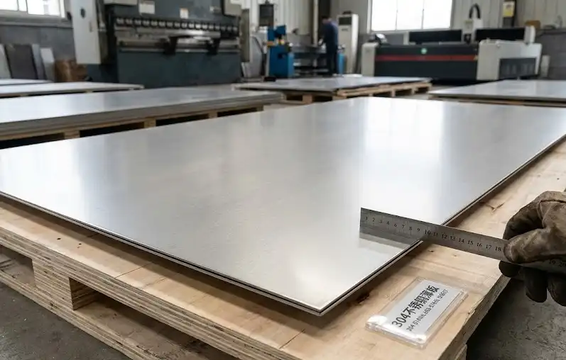
Austenitic 304 and 304L are very weldable, but thin sections move quickly with heat. Distortion and visible heat tint show up fast when heat input climbs or gas coverage falls short. Conservative practice caps interpass temperature around 150 °C to protect corrosion performance and avoid lingering in the sensitization range. Guidance on low heat input technique for stainless is summarized in The Welding Institute’s overview of good practices for stainless and supplementary Nickel Institute notes on heat affected behavior; see the discussion in the TWI stainless guidance and the Nickel Institute overview for context.
- According to the ABS stainless rules that draw on AWS D1.6, procedure variables should be qualified on representative thicknesses and joint types before release to the floor. See the ABS interpretation that references AWS D1.6 for procedure control.
- For arc welding, ER308L is the standard filler for 304 and 304L. A reputable technical guide from Hobart details filler compatibility and process notes.
References in this section:
- ABS referencing AWS D1.6 — “Requirements for Materials and Welding for Stainless Steels” (2022) provides a standards lens on qualifying procedures for stainless. Link used below in the Process controls and verification section.
- Hobart Brothers Stainless Steel Technical Guide supports ER308L selection and gas choices for stainless thin sheet. Linked below in the TIG and MIG sections.
Process selection snapshot for 0.8–1.5 mm cosmetic corner and lap joints
| Process | Best fit scenarios | Pros for thin cosmetic work | Watchouts |
|---|---|---|---|
| TIG GTAW | Short runs, corners and laps that demand top cosmetic quality | Excellent control, low spatter, precise heat placement | Slow if many inches of weld, requires purge on roots and careful gas coverage |
| MIG GMAW pulsed | Longer seams on fixtures where productivity matters | Faster than TIG, stable metal transfer with pulsed programs | Slightly higher heat input, more sensitive to fit-up, gas mix selection affects color |
| Fiber laser | Minimal distortion goals with tight fit-up and dedicated fixturing | Lowest heat input, highest travel speed, clean surface | Demands stable fixturing and very tight gaps; parameter sensitivity requires trials |
Parameter windows to weld 304 stainless steel thin sheet
These are conservative starting bands intended to help you build and qualify your WPS. Always validate on coupons that match your material batch, joint geometry, and fixture thermal mass. Think of them as the “guardrails,” not the destination.
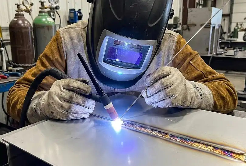
TIG setup and execution
Step 1 — Joint preparation
- Deburr and solvent-clean both faying surfaces and the near-weld area. Aim for tight fit-up on corners and laps. Where accessible, place a copper backing or chill bar under the seam to extract heat.
Step 2 — Shielding and electrodes
- Shielding gas is 100% argon. Typical flow is 10–15 L/min through a #8–10 cup depending on torch and access. Use a 1.0–1.6 mm lanthanated or thoriated tungsten, sharpened with a small flat.
Step 3 — Filler and pulse
- Use ER308L filler at 1.0–1.6 mm when filler is required. Favor pulse TIG to trim heat input. Start with short, consistent arc length and a 10–15° push angle. Travel fast with stringer beads.
Step 4 — Purge for laps and corners
- Where the root is exposed, purge with argon using dams or tape. Start purge around 5–10 L/min to establish, then maintain a gentle 2–8 L/min to avoid turbulence. Continue a short post-flow to protect the hot root.
Step 5 — Interpass control and cooling
- Cap interpass around 150 °C. Use an IR thermometer or a contact probe. Allow cooling breaks between short stitch segments to hold flatness.
TIG pulse starting window for 0.8–1.5 mm 304
| Thickness | Peak current | Background current | Pulse frequency | Duty cycle | Gas flow |
|---|---|---|---|---|---|
| 0.8–1.0 mm | 35–55 A | 10–25 A | 1–3 Hz | 30–50% | 10–14 L/min |
| 1.2–1.5 mm | 45–80 A | 15–35 A | 1–5 Hz | 30–50% | 12–15 L/min |
Evidence and deeper reading: See ESAB’s best practices for thin materials for GTAW technique and gas coverage, and the Hobart stainless technical guide for ER308L selection and additional stainless process notes.
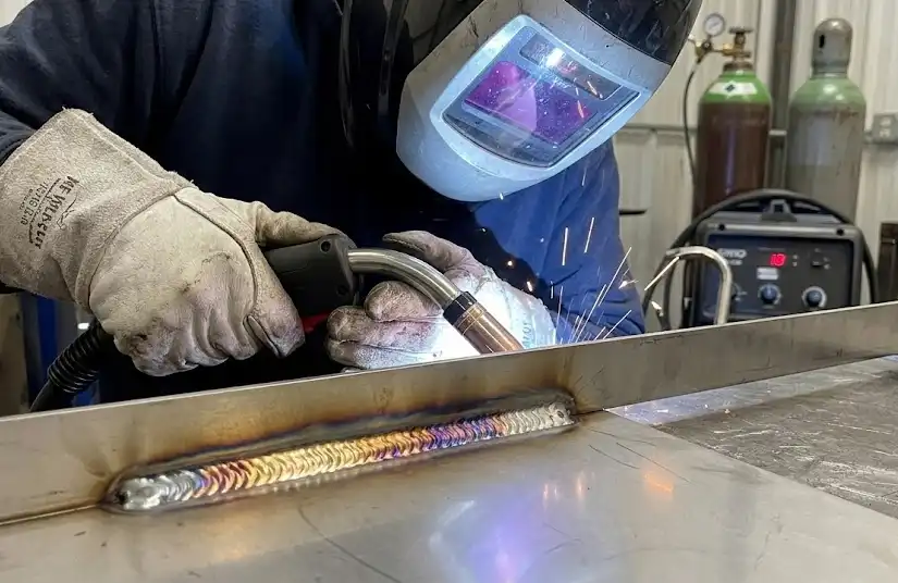
MIG setup and execution
Step 1 — Wire and gas
- Load ER308L wire in 0.8–1.0 mm diameter. Choose an argon-rich gas with very low oxidizers for appearance and corrosion resistance, such as 98% Ar and 2% O₂, or a low-CO₂ tri-mix as specified by your supplier.
Step 2 — Transfer mode and programs
- Favor pulsed spray transfer to stabilize metal transfer on thin sheet. If short-circuit is required, use the lowest stable voltage and wire feed speed that prevent cold lap and burn-through.
Step 3 — Torch technique
- Use a 10–15° push angle with a short stickout of 10–15 mm. Keep the arc on the leading edge and travel fast; avoid weaving.
Step 4 — Sequencing and cooling
- On longer corners or laps, stitch 20–40 mm segments with spacing and cooling intervals to hold flatness. Use heat sinks where practical.
Pulsed MIG starting window for 0.8–1.0 mm sheet with 0.9 mm wire
| Variable | Starting range |
|---|---|
| Wire feed speed | 3.5–5.5 m/min depending on program |
| Transfer | Pulsed program tuned for ER308L |
| Travel speed | 300–600 mm/min with stringer technique |
| CTWD | 10–15 mm |
| Gas flow | 14–16 L/min |
Evidence and deeper reading: Practical MIG stainless guidance is summarized by Miller’s application article on stainless MIG best practices and reinforced by the Hobart stainless technical guide.
Fiber laser setup and execution
Step 1 — Fixturing and focus
- Rigidly clamp the joint to hold gap and maintain focus height. Verify focus on scrap and log the offset in your WPS.
Step 2 — Shielding choice
- Use argon when surface color and cosmetic appearance dominate. Nitrogen can increase penetration or speed on some setups; qualify its use when corrosion behavior is critical.
Step 3 — Power, speed, and oscillation
- Start with autogenous settings suitable for the thickness and joint. Apply wobble to widen the bead and stabilize the keyhole when bridging minor gaps; add wire feed only when needed for larger gaps, then re-qualify.
Autogenous starting bands for 304 in the 0.8–1.5 mm range
| Thickness | Power | Travel speed | Focus offset | Shielding flow |
|---|---|---|---|---|
| 0.8–1.0 mm | 900–1200 W | 25–40 mm/s | ~0 mm | ≥15 L/min Ar |
| 1.5 mm | 1200–1500 W | 20–30 mm/s | ~0 mm | ≥20 L/min Ar |
With gap management, a 1.5–3.0 mm wobble at roughly 60–150 Hz and 0.8–1.0 mm wire can bridge up to about 1.0 mm on 1.0–1.5 mm sheet when fixturing is robust. Vendor application notes illustrate these strategies and are a good starting point for lab trials. See the stainless laser welding application guide for parameters and the general laser welding guide for broader setup reminders.
Process controls and verification you should lock in your WPS
- Document and validate essential variables for your process and joint, then test on coupons before release. The ABS stainless requirements that reference AWS D1.6 outline how to control procedure variables for stainless work; see ABS’s Requirements for Materials and Welding for Stainless Steels.
- Keep interpass temperature near or below 150 °C on thin austenitic stainless and favor fast travel with stringer beads. The Welding Institute’s good practices summary explains why low heat input and short exposure to elevated temperatures help avoid sensitization and preserve corrosion performance.
- For arc processes, standardize on ER308L for 304 and 304L and specify your shielding gas, cups, and purging approach. The Hobart stainless technical guide details filler selection and stainless process notes.
Verification and inspection checklist
- Interpass temperature is controlled and recorded near 150 °C using an IR thermometer or thermocouple.
- Visual tint on cosmetic surfaces is acceptable or removed promptly. Toe transitions are smooth with no undercut. Spatter is minimal.
- Dimensional flatness and camber are within tolerance after cool-down and unclamping. For long corners, measure at intervals.
- For lap joints with root exposure, the backside is fully protected during welding and free of heavy oxidation.
- Post-weld surfaces are cleaned, then passivated; water-break-free condition is confirmed before final release.
Troubleshooting matrix for thin 304 corner and lap joints
| Symptom | Likely cause | Corrective action |
|---|---|---|
| Burn-through | Excess heat or excessive gap | Drop current or voltage, increase travel, tighten fit-up, use copper backing or thicker chill |
| Lack of fusion | Energy too low or poor angle/focus | Modestly raise peak or power, improve joint fit-up, shorten arc or CTWD, for laser add wobble or wire |
| Porosity | Contamination or poor shielding | Clean thoroughly, raise shielding flow without turbulence, check for leaks, consider argon if using nitrogen and porosity persists |
| Heavy heat tint | High heat input or poor purge | Reduce heat input and travel faster, improve shielding and backside purge, remove tint then passivate |
| Warpage or bowing | Cumulative heat and restraint issues | Stitch or skip sequence, stronger fixturing with heat sinks, allow cooling breaks, reduce bead volume and pulse settings |
Cleaning and passivation for corrosion performance
Heat tint weakens the passive film and can harbor contamination on hygienic surfaces. Remove visible tint and oxides, then passivate per recognized practices. Two companion references outline what “good” looks like and how to verify it:
- The British Stainless Steel Association’s pickling and passivation primer explains why you must clean or pickle first and then passivate; passivation alone does not remove oxide scale.
- ASTM A967 describes chemical passivation methods for stainless along with verification tests such as water immersion, humidity, and copper sulfate; pair it with the cleaning practice summarized in ASTM A380 when writing your SOP.
After chemical treatment, rinse and neutralize per product instructions, then confirm a water-break-free surface. Where specified, perform additional verification such as a copper sulfate or ferroxyl test before sign-off.
Safety and environmental notes
Welding fume from stainless requires attention to ventilation and PPE. The safety standard often cited for welding, cutting, and allied processes outlines expectations for fire prevention, ventilation, and personal protection. Review the current AWS Z49.1 publication or equivalent safety guidance within your organization before production, and ensure chemical handling procedures for pickling and passivation follow your site’s EHS rules.
A quick heat input reminder
When your code or customer requires it, compute heat input as part of procedure control:
Heat Input (kJ/mm) = (Voltage × Current × 60) / (1000 × Travel Speed in mm/min)
You’ll generally want to operate at the low end of typical stainless ranges on thin sheet to maintain appearance and minimize distortion. Use this as a comparison tool when tuning pulse parameters and travel speed.
References and further reading
- ESAB University — Best practices for welding thin materials provides GTAW technique and shielding coverage context for thin stainless: https://esab.com/am/eur_en/esab-university/articles/best-practices-for-welding-thin-materials/
- Hobart Brothers — Stainless Steel Technical Guide covers ER308L selection and stainless process notes: https://www.hobartbrothers.com/wp-content/uploads/2021/06/Stainless_Steel_Technical_Guide.pdf
- Miller — Stainless steel MIG best practices article summarizing process and gas choices: https://www.millerwelds.com/resources/article-library/want-to-improve-results-when-mig-welding-stainless-steel
- GWK — Stainless laser welding guide with parameter concepts for 0.5–4.0 mm stainless: https://www.gwklaser.com/about/technical/stainless-steel-laser-welding-guide.html
- ABS — Requirements for Materials and Welding for Stainless Steels referencing AWS D1.6 for procedure control: https://ww2.eagle.org/content/dam/eagle/rules-and-guides/current/other/302-requirements-for-materials-and-welding-for-stainless-steels/302-stainless-steel-reqts-july22.pdf
- BSSA — Pickling and Passivation primer on removing heat tint and restoring corrosion resistance: https://bssa.org.uk/wp-content/uploads/2021/07/Pickling-and-Passivating-Stainless-Steel.pdf
- ASTM A967/A380 — Chemical passivation and cleaning practice summaries: https://www.astm.org/a0967_a0967m-17.html and https://www.astm.org/a0380_a0380m-17.html
- AWS Z49.1 — Safety in welding, cutting, and allied processes free view: https://pubs.aws.org/content/free_downloads/AWS-Z49-2021.pdf
—
Final reminder
Qualify your chosen window on coupons first, then lock essential and nonessential variables in your WPS for each joint type. That’s how you consistently weld 304 stainless steel thin sheet with minimal distortion and clean appearance on the line.