Introduction
Laser oxide removal lives or dies by selectivity. You want the oxide gone, the base metal untouched, and you want to do it quickly—without rework or hidden heat-affected zones. That’s the promise of pulsed laser cleaning when it’s set up and monitored correctly.
At its core, the method exploits differences between oxide layers and bulk metal: how they absorb light, how heat diffuses during a short pulse, and how plume and shock effects help eject the brittle top layer before the substrate can heat to melting. Put those pieces together and you get a process window that is forgiving enough for production but tight enough to avoid damage.
This guide is written for process, manufacturing, and quality engineers who need the “why” and the “how”: the physics that explains the selectivity and the parameters, guardrails, and QA practices that keep the substrate safe.
Key takeaways: pulsed laser cleaning selectivity
- Short, nanosecond pulses confine heat to micrometer scales; set fluence just above the oxide-cleaning onset and scan fast enough to avoid cumulative heating.
- Oxides generally couple more light and have lower effective ablation/cleaning thresholds than the base metal; staying between those thresholds is the selectivity sweet spot.
- 1064 nm is the workhorse for steels; try 532 nm when aluminum alloys or thin Al2O3 films reflect too much at 1064 nm.
- Start with conservative fluence–speed–overlap windows for each metal, validate on coupons, and define stop/abort criteria from inline signals before scaling.
- A simple QA stack—plume/vision/thermal sentinels plus microscopy—prevents substrate melting and locks in repeatability.
Physics of selectivity
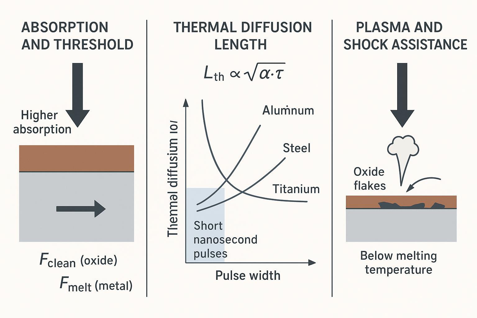
Laser cleaning removes oxides without melting the underlying metal by combining threshold contrast, thermal confinement during short pulses, and photomechanical assistance from the transient plume and shockwave. Here’s how the pieces fit.
Absorption and threshold contrast
Every material exhibits a threshold fluence (energy per area) above which removal becomes efficient. Common corrosion oxides and residues absorb more strongly and often have lower effective removal thresholds than the bulk metal beneath. By tuning the fluence just above the oxide’s cleaning threshold while staying below the substrate’s melting or ablation threshold, the oxide ejects while the metal remains intact. Reviews of pulsed ablation fundamentals explain this threshold-governed selectivity clearly; see the practical overview in the peer-reviewed tutorial by Shepelin and colleagues in 2023, which details pulse–matter coupling and threshold behavior in pulsed regimes, even though their context is thin-film deposition, the physics maps directly to industrial cleaning processes. For layered corrosion oxides on steel, experimental work shows a usable band between cleaning and damage thresholds, with removal deepening as peak power density rises and substrate effects appearing only when energy density and dwell accumulate at slow scans; Ren and coauthors reported this stepwise removal behavior in 2022 for 1064 nm systems. You can read the mechanisms in the accessible summaries by the authors in the following sources: the comprehensive tutorial in Nature Reviews Methods Primers (2023) and the oxide-on-steel study (2022). Links: the pulsed ablation tutorial is in the article A practical guide to pulsed laser deposition (2023), and the stepwise rust removal behavior is discussed in Stepwise Removal Process Analysis Based on Layered Corroded Oxides (2022).
According to the authors’ own framing, the practical implication is simple: find the oxide-cleaning onset, then stay below any substrate discoloration or melt indicators while scanning fast enough to prevent accumulation.
Thermal diffusion and pulse width
Thermal diffusion length, often estimated as L_th ≈ (2·α·τ_p)^{1/2}, sets how far heat penetrates during one pulse, where α is thermal diffusivity and τ_p is pulse width. Shorter nanosecond pulses confine heat to micrometers or less per pulse. For representative room-temperature values, aluminum’s high diffusivity yields L_th on the order of a few micrometers at 100 ns, while carbon steel and titanium confine even more tightly at the same τ_p. That confinement is why pulsed laser cleaning can lift an oxide cleanly when fluence and scanning keep the substrate below melting. For a concise treatment of pulsed-heating temperature fields with usable expressions, see the open-access paper Usable Analytical Expressions for Temperature Distribution Under Pulsed Laser Heating (2024), which complements the threshold perspective in the 2023 tutorial cited above.
Think of it this way: each pulse is a tiny, timed nudge that affects mostly the surface oxide; by the time heat could spread deeper, the pulse has ended and the scanner has already moved on.
Plasma and shockwave assistance
Short, intense pulses generate a transient vapor plume and occasionally a weak plasma above the surface. The rapid expansion produces a pressure wave that helps dislodge brittle oxides and weakly adhered contaminants. In the cleaning literature, this photomechanical assistance shows up alongside photothermal effects and is especially helpful when the oxide is layered or cracked. A recent review that surveys these mechanisms and warns about byproducts and fume control is the paper Characteristic and mechanism of pollution by laser cleaning (2024), which emphasizes plume behavior and environmental controls relevant to production setups.
Pulse parameters in pulsed laser cleaning that protect metal
The core levers are fluence, wavelength, repetition rate, and how you scan. Use them to sit in the oxide-removal band while keeping the substrate below melting and avoiding cumulative heating.
Fluence windows and overlap
As a conservative starting point on rusted carbon steel at 1064 nm with nanosecond pulses, begin around 0.3–1.0 J/cm² for light rust and expand cautiously toward 1.0–3.0 J/cm² for heavier rust or mill scale. These are engineering heuristics, not universal thresholds; validate on coupons and watch your endpoints. Hold overlap in the 50–60% range to ensure coverage without over-dosing the same spot, and prefer two light passes over one heavy pass. When you push fluence upward, increase scan speed or reduce overlap to avoid cumulative heating. For context on how energy density and dwell time interplay with coating removal behavior and substrate effects, see the open study Effect of Defocused Nanosecond Laser Paint Removal on Mild Steel (2021), which, although on paint, illustrates the importance of defocus, overlap, and speed on accumulation.
Wavelength choices: 1064 vs 532 nm
For steels, 1064 nm is the default because it is widely available in robust pulsed fiber sources and couples adequately into iron oxides. For highly reflective aluminum alloys or thin native Al2O3 films, trials at 532 nm often improve coupling, lowering the required fluence and widening the selectivity band. Optical property datasets report higher reflectance at 1064 nm than at 532 nm for aluminum near-normal incidence; practical experience echoes this: when you see poor plume at 1064 nm on clean-but-oxidized aluminum while temperatures still rise, switching to 532 nm can restore efficient oxide ejection. Treat wavelength as a lever, not a doctrine—validate on the actual alloy and surface condition.
Repetition rate and scanning
Repetition rate drives peak power density and cumulative dosing per unit area once combined with speed and overlap. A pragmatic range for handheld or galvo cleaning lies between 20–200 kHz, extending higher for throughput in well-cooled, fast-scanning cells. Start around 1000–3000 mm/s and adjust: if plume brightness grows from line to line or a thermal camera shows drift upward across a hatch, raise speed, widen hatch spacing, or drop pulse energy. An orthogonal 0/90° hatch with inspection between passes helps prevent unintentional substrate exposure.
Metal-specific windows
These windows are indicative starting points assembled from mechanism literature, coating-removal studies, and shop-floor practice. They are not substitutes for on-part validation. Document your chosen recipe and the stop/abort criteria before production.
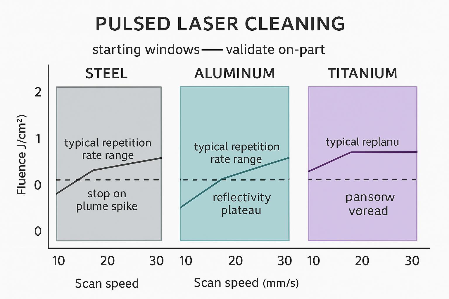
Steel: rust and mill scale
For light rust, start near 0.3–1.0 J/cm², 20–200 kHz, 1000–3000 mm/s, and 50–60% overlap. As oxides thicken or you encounter mill scale, extend to 1.0–3.0 J/cm² but trade that increase for speed to keep cumulative energy per area in check. Expect layered removal: reflectivity will climb and then plateau; micrographs at 50–200× should show a crisp surface with no micro-melt pools or pits. Experimental studies on rusted steel at 1064 nm confirm this stepwise removal behavior and the existence of a usable band between cleaning and damage thresholds; the authors of the 2022 oxide-layer study provide a helpful framework for interpreting power density vs. scan speed in that context.
Aluminum: reflective alloys
Begin with 532 nm trials for thin oxide films or when 1064 nm coupling is poor: 0.2–0.8 J/cm², 50–300 kHz, and higher scan speeds such as 2000–6000 mm/s with 40–60% overlap. If 1064 nm remains necessary for system reasons, try 0.5–2.0 J/cm² while ensuring fast motion and minimal overlap to avoid brightening the bare aluminum excessively—an indicator you’ve passed the endpoint. Your simplest in-line cue is a stable, modest plume followed by a reflectivity plateau. Post-process, avoid whitening or pitting; if you see either, you overdosed the bare substrate.
Titanium: stable oxide films
Titanium’s oxide films are thin and stable. Start at 0.2–0.8 J/cm² at 1064 nm, 20–150 kHz, 1000–3000 mm/s, and 40–60% overlap. Multiple light passes are safer than single heavy ones due to Ti’s lower thermal diffusivity. Endpoints include the fading of interference colors and a steady reflectivity; microscopy should reveal no roughness spikes or smeared features.
Process optimization and QA
Robust oxide removal without substrate melt is a matter of guardrails, instrumentation, and disciplined tuning. The physics gives you the window; the process keeps you inside it.
Guardrails to prevent melting
Establish a validated fluence band on coupons that begins just above the oxide-cleaning onset and remains below any substrate discoloration or micro-melt indicators. Control cumulative energy per area by pairing fluence with speed and overlap so that line-to-line plume brightness remains steady rather than trending upward. Use temperature sentinels from a thermal camera or pyrometer to cap apparent surface rise at the value observed to be safe in your trials; when the plume brightens abruptly or reflectivity stops rising, pause—those are your natural stop points. Inspect between passes at magnification and, when in doubt, reduce energy density and increase speed.
In-line monitoring and validation
Plume monitoring, reflectivity imaging, and thermal sensing together create reliable stop/abort criteria. The cleaning mechanisms literature ties plume and transient plasma behavior to the transition from coating/oxide ablation to substrate exposure; use that correlation to set relative-intensity thresholds. For higher-end cells, LIBS can mark the change in spectral lines as you reach the substrate, offering a strong endpoint cue if properly integrated. For safety management and enclosure design, lean on established frameworks such as the OSHA overview of the ANSI Z136 series and plant-level guidance based on ANSI Z136.1-2022; these outline classification, engineering controls, PPE, and controlled-area practices appropriate for Class 4 cleaning cells.
References for safety context: see OSHA’s summary page on laser hazards (links to Z136 series) and a representative university Laser Safety Guide (2023) based on ANSI Z136.1-2022 that explains practical controls in plain language.
Tuning workflow and documentation
Run a small DOE on coupons: sweep fluence, scan speed, and overlap within conservative limits; instrument plume intensity and temperature; inspect after each pass under 50–200×; then lock a recipe with explicit stop and abort thresholds. Your minimal documentation should capture the material condition, laser setup (wavelength, pulse width, spot size), starting window, monitoring thresholds (plume change %, reflectivity plateau, max apparent temperature), pass/fail criteria, micrographs, operator notes, and a versioned sign-off. This record is what keeps trials reproducible across shifts and sites.
Oceanplayer preset and guardrails (concise, neutral example): On thin rusted mild steel with a pulsed fiber source in the nanosecond regime, start near 0.4 J/cm² with about 60% overlap at 30–80 kHz and 1500–2500 mm/s using a 0/90° hatch. Set a plume-intensity stop trigger at roughly +20–30% above the baseline established during oxide removal and cap the apparent surface temperature rise to your coupon-validated limit; if plume spikes early, increase scan speed to 3000–4000 mm/s or reduce pulse energy by 10–20%. Verify under 100× microscopy and confirm reflectivity plateau before scaling throughput. Systems from Oceanplayer can be configured with presets and guardrails along these lines; keep them conservative until in-line signals and micrographs validate headroom.
Conclusion
The governing rule is balance: set fluence high enough to eject the oxide, keep pulses short and scanning fast to confine heat, and stop the moment in-line signals say you are at bare metal. The physics—threshold contrast, thermal confinement, and plume/shock assistance—creates the window; a disciplined process keeps you from drifting past it.
A practical start-up recipe looks like this: find the oxide-cleaning onset with short pulses and fast scanning; hold overlap around 50–60%; increase speed when fluence climbs; validate each change with plume intensity trends, reflectivity plateaus, and a thermal cap observed during trials; inspect micrographs between passes. Scale throughput only after you’ve locked stop/abort thresholds and documented the recipe.
Final verification checklist before production
- Confirm the validated fluence–speed–overlap window on coupons produces clean removal without micro-melt or pits under 50–200×.
- Confirm in-line stop criteria: plume relative-intensity threshold and reflectivity plateau; confirm an abort temperature cap.
- Confirm environmental controls: fume extraction appropriate for ablation byproducts and an enclosed, interlocked Class 4 area aligned with ANSI/IEC/ISO expectations.
- Confirm documentation: recipe version, material condition, monitoring thresholds, acceptance criteria, and sign-off.
Selected references for further reading
- According to the tutorial in Nature Reviews Methods Primers, A practical guide to pulsed laser deposition (2023), pulsed ablation thresholds and pulse-duration effects explain why short pulses enable selective removal: https://pmc.ncbi.nlm.nih.gov/articles/PMC10068590/
- The oxide-on-steel study Stepwise Removal Process Analysis Based on Layered Corroded Oxides (2022) discusses usable bands between cleaning and damage thresholds at 1064 nm: https://pmc.ncbi.nlm.nih.gov/articles/PMC9654925/
- Usable Analytical Expressions for Temperature Distribution Under Pulsed Laser Heating (2024) offers compact formulae for thermal fields during pulses: https://pmc.ncbi.nlm.nih.gov/articles/PMC10890633/
- Characteristic and mechanism of pollution by laser cleaning (2024) reviews plume and byproduct mechanisms relevant to cleaning cells: https://pmc.ncbi.nlm.nih.gov/articles/PMC12744604/
- OSHA’s overview of the ANSI Z136 laser safety series points to U.S. best practices for Class 4 processing environments: https://www.osha.gov/laser-hazards/standards
- A representative plant-level guide based on ANSI Z136.1-2022 is the Purdue REM Laser Safety Guide (2023): https://www.purdue.edu/ehps/rem/documents/programs/laserguide.pdf