If your mandate is more parts per hour without saddling downstream ops with heavy deburr, fiber laser cutting is an excellent route for aluminum sheet in thin-to-medium gauges. The goal here isn’t “the shiniest edge at any cost,” it’s repeatable takt time with edges clean enough for welding, forming, or coating—no drama, no surprises. Think 5052-H32 panels at 2–3 mm or 6061-T6 brackets at 4–6 mm where stable ejection, consistent kerf, and predictable small features keep the cell moving.
This guide distills proven parameter windows and shop-floor tactics to push throughput while keeping edge quality within spec. We’ll use nitrogen as the baseline assist gas, cover when compressed air is a pragmatic alternative, and explain how nozzle diameter, standoff, and focus position affect dross and speed. We’ll also address safety for reflective materials (back-reflection) and Class 1 operation with authoritative references.
Key takeaways
- Use nitrogen when you need oxide-free, weld-ready edges; use clean, dry compressed air on ≤3–4 mm when light oxidation is acceptable and you prioritize cost and speed.
- For fiber laser cutting aluminum, start with conservative speed windows, then climb: on nitrogen, ≈1–3 m/min for ≤3 mm, ≈0.5–1.5 m/min for 3–6 mm, and ≈0.2–0.8 m/min for >6–10 mm—machine-, head-, and alloy-dependent.
- Throughput levers that matter most: adequate nitrogen pressure/flow, correct nozzle size with short standoff, clean optics, short pierces, generous corner radii, and smart cut order.
- Kerf is narrow (≈0.20–0.30 mm typical), which is great for nesting density but sensitive to ejection stability—watch micro-dross and keep webs reasonable.
- Back-reflection is a real hazard on aluminum: don’t bypass monitoring, operate as a Class 1 enclosed system, and align programs with ANSI Z136.1 under an LSO’s oversight; OSHA’s laser guidance points to this framework.
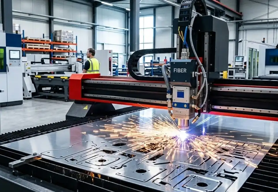
Why choose fiber laser when speed is king
Aluminum reflects strongly at room temperature around the fiber wavelength (~1.06 µm), but at cutting intensities with proper focus and assist gas, fiber lasers deliver high power density and excellent beam quality. That combination supports fast, consistent melting and ejection in thin-to-medium gauges—exactly where throughput is won.
Independent overviews confirm aluminum’s suitability for fiber laser cutting and outline capability ranges for speed and feature size. For a balanced grounding on feasibility and practical constraints, see the material overview in Xometry’s guide to aluminum laser cutting and a discussion of fiber laser limits and optimization considerations in ADH Machine’s capability article. Both provide context on thickness ranges and production outcomes without prescribing OEM-specific numbers. Read: the aluminum suitability and speed context in the industry guide Laser Cutting Aluminum from Xometry and the capability ranges noted in ADH Machine’s Fiber Laser Cutting Limits and Optimization articles.
Assist gas selection for aluminum: nitrogen vs air (and why oxygen is out)
When the target is speed with acceptable edges, assist gas is the first big lever.
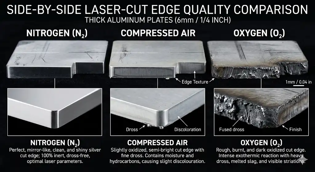
- Nitrogen (preferred baseline): Delivers clean, oxide-free edges and minimizes heat tint—ideal for weld prep and finishing. Typical operation is high-pressure to help expel melt and suppress re-adhesion. Practical primers from process resources outline why nitrogen is standard for nonferrous quality cutting and how gas choice influences speed and roughness; for example, the assist-gas explainers by RDI Laser Blanking and the parameter primers by ACCURL provide concise, vendor-agnostic reasoning.
- Compressed air (thin-gauge, cost-focused): On ≤3–4 mm aluminum, dry, filtered, boosted shop air can be fast and economical if slight oxidation/discoloration is acceptable. Several industry primers (e.g., SENFENG knowledge base and comparative gas articles) discuss where air can replace nitrogen without wrecking quality targets.
- Oxygen (generally avoid): Oxygen promotes exothermic reactions that roughen and oxidize aluminum cuts—fine for steels, not for weld-ready aluminum. This is repeated in multiple assist-gas comparisons, including RDI’s overview and Triumph’s gas consumption analysis.
Table A summarizes pragmatic, defensible starting points.
| Assist gas | Primary objective | Typical pressure guidance | Notes |
|---|---|---|---|
| Nitrogen | Clean, oxide-free edges; minimal heat tint | ≈8–20 bar for thin-to-medium; up to ≈15–30 bar to suppress micro-dross when thickness increases | Prioritize purity (≥99.95%); verify head flow capacity and nozzle size. See process primers on nitrogen cutting and parameter setup in ACCURL’s resources and the assist-gas selection guidance by RDI Laser Blanking. |
| Compressed air | High speed and low operating cost on thin stock | ≈15–30 bar with boosters/dryers/filters | Accept slight oxidation/discoloration; use only when finish requirements allow. Practical notes are compiled in ACCURL gases primers and SENFENG’s selection guidance. |
| Oxygen | Avoid for aluminum | N/A | Typically unsuitable for aluminum quality cutting due to rough, oxidized edges. Reiterated across comparative gas explainers including RDI and Triumph. |
Citations (selected): see the assist-gas selection context in RDI Laser Blanking’s guide, ACCURL’s parameter and gas primers, and SENFENG’s knowledge post on choosing gases for fiber laser cutters.
Speed and power windows by thickness on nitrogen
Exact numbers vary by machine optics, head, nozzle, gas delivery, alloy, temper, and surface finish. Public, OEM-specific charts that tie thickness directly to power bands (3, 6, 12 kW) are rarely published. Instead, use conservative “validated starting windows,” then push speed as monitoring (spark pattern, audible tone, top/bottom bead) and cut-face photos confirm stable ejection.
- Thin (≤3 mm): ≈1–3 m/min baseline; higher powers in the 6–12 kW range can drive toward the upper end if gas flow keeps up.
- Medium (3–6 mm): ≈0.5–1.5 m/min depending on alloy and finish targets; nozzle flow capacity and pressure become critical.
- Thick end of range (>6–10 mm): ≈0.2–0.8 m/min with strong emphasis on flow, stable focus, and thermal management.
These bands synthesize values reported in reputable overviews. For representative context on speeds and feasibility, see the material-focused Laser Cutting Aluminum explainer by Xometry and the capability discussion in ADH Machine’s optimization article. For how parameters interact (focus, nozzle, power), ACCURL’s parameter primer provides a useful qualitative model.
Table B consolidates the thickness-centric view and adds the power-directional note engineers typically apply on the floor.
| Thickness band | Indicative speed range on N2 | Power-directional note |
|---|---|---|
| ≤3 mm | ≈ 1,000–3,000 mm/min (≈1–3 m/min) | Higher available power (6–12 kW) tends to support operation near the upper end if gas flow and focus are optimized. |
| 3–6 mm | ≈ 500–1,500 mm/min (≈0.5–1.5 m/min) | Mid-to-high power plus larger nozzles/pressure help maintain ejection and reduce dross. |
| >6–10 mm | ≈ 200–800 mm/min (≈0.2–0.8 m/min) | Expect diminishing returns from power alone; gas delivery and focus stability dominate. |
Note on scaling: Speed does not increase linearly with power due to melt-ejection physics and gas-flow limits. Practical primers, such as ACCURL’s parameter discussions, explain why nozzle size, standoff, and focus can cap speed before raw wattage does.
Nozzle diameter, standoff, and focus: the hidden speed governors
Even with ample power, poor ejection control throttles throughput. Three mechanics dominate:
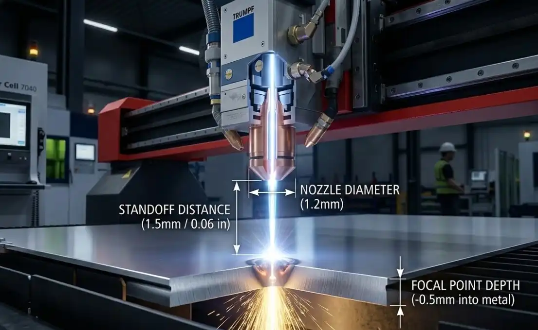
- Nozzle diameter: Smaller nozzles concentrate flow for thin gauges and tight features; larger nozzles increase flow for thicker sections. As a rule of thumb, thin aluminum often runs well with ≈1.0–2.0 mm nozzles, while thicker work benefits from ≈2.5–3.0 mm to sustain high nitrogen flow.
- Standoff distance: Keep standoff roughly at or below the nozzle diameter (≈0.5–1.0 mm in many heads) to maintain a strong, coherent jet. Excessive standoff invites turbulence and micro-dross.
- Focus position: For continuous cutting on aluminum with nitrogen, start near surface to slightly below top face; adjust in small steps to stabilize the plume and minimize bottom dross. Too deep a focus can widen kerf and slow ejection; too shallow can destabilize the cut.
Process primers such as ACCURL’s parameter overviews connect these adjustments to real cut outcomes without prescribing a single “correct” number, which depends on the cutting head and optics.
A practical tuning playbook for throughput without dross
Here’s the deal: you’ll move faster by changing one thing at a time and watching ejection stability like a hawk. Prioritize in this order:
- Gas first: Use high-purity N2 (≥99.95%) and ensure pressure/flow capacity matches thickness. If micro-dross persists on mid-gauges, increase pressure or upsize the nozzle before you add more power.
- Focus and standoff: Nudge focus just below the surface and keep standoff short to stiffen the jet. Re-confirm nozzle alignment/coaxiality after a tip change.
- Entry strategy: Short, controlled pierces (or pre-pierce) with angled lead-ins minimize spatter that seeds dross. Shorten pierce time as stability allows.
- Geometry for speed: Add small internal corner radii (e.g., ≥0.5 mm) and avoid hairpin turns that force deceleration. Use microjoints to prevent part tip-up on dense nests.
- Cut order: Do small holes/features first while the sheet is stiff; cluster contours to reduce traverse time; leave skeleton locks until final cuts.
- Optics hygiene: Keep protective glass clean and replace worn nozzles—both can masquerade as parameter problems and cost you minutes per sheet.
Corner and small-feature management tips from industry tech notes—such as Mazak’s discussion on cutting corners and small features—underline why geometry and control modes matter when chasing speed.
Kerf width, tolerances, and nesting density
Typical kerf with fiber laser cutting aluminum is narrow—on the order of ≈0.008–0.012 in (≈0.20–0.30 mm)—widening with thickness. Service-bureau capability pages summarize what designers can expect for tolerances and small features; for example, Xometry’s metal laser cutting capability pages and SendCutSend’s kerf FAQ outline practical kerf and tolerance bands used in quoting and QA.
Implications for throughput:
- Tighter nests thanks to narrow kerf yield more parts per sheet and fewer traverses, but increase risk of thermal interaction and part tip-up. Use microjoints and avoid ultra-thin webs on dense nests.
- Small holes/slots: Use lead-ins and consider a short “finish lick” only when required by downstream fits; otherwise, accept a slightly rougher but in-spec edge and move on.
Quality control and fast troubleshooting
When speed creeps up, defects show up first at the bottom edge and in corners. Triage quickly using these signals:
- Bottom dross beads: Increase assist pressure or upsize the nozzle; verify focus slightly below surface; slow marginally or raise power if ejection still unstable.
- Hazy oxide/discoloration on air: Confirm air dryness/filtration and that finish requirements permit air; switch to nitrogen if weld prep demands oxide-free.
- Striations and wide kerf: Re-center the nozzle and clean/replace the protective window; reduce standoff; fine-tune focus.
- Incomplete cuts on small features: Cut holes first, increase dwell slightly on entry, and confirm the jet is coherent (nozzle damage often mimics lack of power).
For formal surface-quality expectations, align inspection with the ISO 9013:2017 thermal cutting classification, which provides terminology and quality ranges relevant to laser-cut faces.
Safety and compliance for reflective materials
Aluminum’s reflectivity makes back-reflection a core hazard: reflected energy can travel back through the optics and delivery fiber if the system is misused or protections are bypassed. Operate high-power cutting systems as enclosed Class 1 machines with functional interlocks, and never defeat back-reflection monitoring.
- OSHA guidance: OSHA’s laser hazards resources point to the ANSI Z136 series as the consensus framework for classifications, maximum permissible exposures, and engineering controls in cutting cells. See OSHA’s Laser Hazards Standards overview for regulatory context.
- ANSI Z136.1 program: The Z136.1 standard (administered by the Laser Institute of America) defines the Laser Safety Officer role, hazard evaluation, training, eyewear optical density selection, and procedural controls. Acquire and implement the 2022 edition and train to it under your LSO’s direction. An overview of the ASC Z136 committee and training pathways is available from the Laser Institute of America.
- Open Class 4 servicing: When doors are open for setup/service, switch to LSO-approved procedures and wavelength-appropriate eyewear with sufficient optical density. Confirm beam paths are contained and reflective hazards mitigated.
Representative references: OSHA’s Laser Hazards Standards page; Laser Institute of America’s ASC Z136 overview and training resources.
Worked examples: converting speed to takt time and parts/hour
Example A — 3 mm 5052 on nitrogen, 6 kW
- Sheet: 1200 × 2400 mm, nest of 40 bracket parts, each with 300 mm of cut length
- Total cut length: 12,000 mm (40 × 300)
- Speed window: start at 1.2 m/min (1,200 mm/min), tune toward 1.8 m/min if ejection is stable
- Pure cutting time: 12,000 ÷ 1,200 = 10.0 min (baseline) → 12,000 ÷ 1,800 ≈ 6.7 min (optimized)
- Add 20% for pierces, traverses, and corner slowdowns: 12.0 min baseline → ≈8.0 min optimized
- Parts/hour: 40 ÷ 12.0 × 60 ≈ 200 pph baseline → 40 ÷ 8.0 × 60 = 300 pph optimized
- Takeaway: A stable bump from 1.2 to 1.8 m/min yields ≈50% more throughput with no extra deburr when dross is controlled.
Example B — 1 mm aluminum on dry compressed air, 12 kW (cost- and speed-focused)
- Sheet: 1000 × 2000 mm, nest of 120 grille parts, each with 150 mm of cut length
- Total cut length: 18,000 mm
- Typical achievable speed on air: use 3.0 m/min as a practical target (machine- and geometry-dependent)
- Pure cutting time: 18,000 ÷ 3,000 = 6.0 min
- Add 25% for numerous pierces and tight features: 7.5 min total
- Parts/hour: 120 ÷ 7.5 × 60 = 960 pph
- Caveat: Expect light oxidation; acceptability depends on finish requirements. If unacceptable, switch to nitrogen and revisit pressure/flow.
Sources and further reading
- Material suitability and practical ranges for aluminum in laser cutting are summarized in Xometry’s resource article Laser Cutting Aluminum: Everything You Need To Know (2026), which provides context on thickness, kerf, and design choices: https://www.xometry.com/resources/sheet/laser-cut-aluminum/
- Capability ranges and optimization considerations for fiber lasers are discussed in ADH Machine’s overview Fiber Laser Cutting Limits and Optimization (2026): https://www.adhmt.com/laser-cutting-machine-limitations/
- Parameter interactions (nozzle, focus, pressure, power) and assist-gas roles are explained in ACCURL’s primers on laser cutting parameters and gases (2024): https://www.accurl.com/blog/laser-cutting-parameters/ and https://www.accurl.com/blog/laser-cutting-gases/
- Comparative assist-gas selection for nonferrous cutting, with notes on nitrogen’s role for quality edges, appears in RDI Laser Blanking’s explainer (2023): https://rdilaserblanking.com/which-assist-gas-should-i-use-for-fiber-laser-cutting/
- Choosing gases for fiber laser cutters (including when air is viable) is covered in the SENFENG knowledge base (2024/2025): https://www.senfenglaser.com/knowledge/choosing-the-right-gases-for-fiber-laser-cutters/
- Kerf/tolerance context used by service providers can be found in SendCutSend’s kerf FAQ (2023): https://sendcutsend.com/faq/what-is-the-size-of-your-laser-kerf/
- Corner/small-feature handling that impacts speed is discussed in Mazak’s tech tip on cutting corners and small features: https://www.mazakoptonics.com/moc-en/news-media/tech-tips/Cutting-Corners-and-Small-Features/
- OSHA’s Laser Hazards Standards page provides the regulatory anchor that points to ANSI Z136 for program-level controls: https://www.osha.gov/laser-hazards/standards
- The Laser Institute of America maintains the ASC Z136 program information and training pathways supporting ANSI Z136.1 (2022): https://z136.lia.org/committees and https://www.lia.org/training/in-house
Disclosure and validation note: All numeric values are validated starting windows synthesized from reputable industry resources. Actual achievable speeds and qualities depend on machine OEM, cutting head, beam quality (M²), optics condition, gas delivery, alloy/temper, and surface condition. Always confirm with your machine’s cut database and on-machine trials before locking takt-time commitments.


