Introduction
Intergranular corrosion (IGC) in austenitic stainless steels arises when chromium carbides precipitate at grain boundaries and locally deplete chromium, undermining passivity. The sensitization window—roughly 425–860 °C—creates risk when a thermal cycle dwells in that band long enough for precipitation to occur. Compared with gas metal arc welding (GMAW/MIG), laser welding concentrates energy in a small interaction zone and moves fast, which shrinks the heat‑affected zone (HAZ) and slashes time in the sensitization range. This guide explains the thermal mechanisms behind that advantage, then shows how to verify outcomes using standards, choose practical parameter windows, plan post‑weld treatments, and set up a quality assurance (QA) program that proves corrosion resistance in production.
Key takeaways
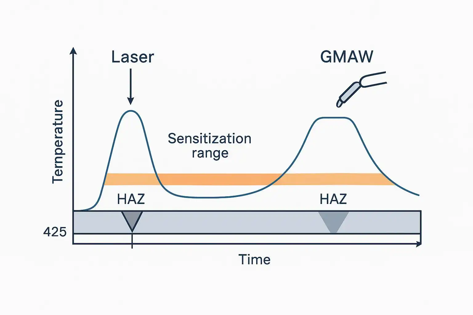
- Laser welding’s high power density and travel speed reduce HAZ width and time in the 425–860 °C sensitization range for 304/316L.
- Treat standards as verification tools: use ASTM A262 practices and DL‑EPR to screen and confirm IGC susceptibility in weld/HAZ.
- Translate mechanism to practice: aim for low linear energy with sufficient penetration; control focus/spot and robust primary/trailing shielding.
- Post‑weld finishing matters: remove heat tint, clean, and passivate to restore chromium‑rich passive films before corrosion testing.
- QA that convinces: define sampling across fusion line/HAZ, pair metallography with A262 or DL‑EPR, and use ASTM G150 CPT as a complementary check.
Thermal mechanism
Rapid heating and cooling
Laser welding deposits energy in a tiny interaction area and at much higher travel speeds than MIG. The result is rapid heating to peak temperature and rapid cooling back through the sensitization band. Less cumulative time between ~425–860 °C means fewer chromium carbides form at grain boundaries, lowering the chance of ditch structures and intergranular attack in screening tests. General process explainers consistently report that focused, high‑speed laser welding produces narrow HAZs compared with traditional arc processes, which supports lower dwell in the critical range; see the engineering overview in the ESAB University article on process differences for a concise comparison of energy concentration and HAZ behavior.
According to the Nickel Institute’s stainless guidance, sensitization is fundamentally a time–temperature phenomenon in austenitics; lowering either parameter curtails carbide precipitation. Laser welding does both: it reduces the time at temperature and limits the heated volume.
- Reference context: the Nickel Institute details high‑temperature behavior and sensitization considerations in austenitic grades in its technical compendium (temperature ranges and mechanisms described) — see their overview on high‑temperature characteristics.
Narrow HAZ and limited dwell
The HAZ governs where sensitization risk concentrates. MIG’s broader thermal footprint and slower thermal cycles typically create a wider HAZ and longer dwell at intermediate temperatures. In contrast, laser’s steep thermal gradients restrict the HAZ laterally and in depth. A narrower HAZ directly reduces the boundary area exposed to sensitizing conditions. For definitions and implications of HAZ size on weld properties, see the clear explanation by TWI on the heat‑affected zone and why its extent matters for microstructure and properties.
Practically, this means a well‑tuned laser weld on 304/316L tends to start from a lower IGC risk position than an otherwise comparable MIG weld—provided cleanliness, shielding, and surface finishing are controlled. It’s not immunity; it’s probability management through the thermal cycle.
Keyhole vs. conduction mode
Laser welding operates in two regimes. In conduction mode (lower power density or deliberate defocus), heat flows from the surface inward, creating shallow penetration and extremely small molten volumes—useful for thin sections and when minimal HAZ is a priority. In keyhole mode (higher power density), a vapor cavity forms, enabling deep, narrow penetration with still‑limited lateral spread. Stability is crucial in keyhole welding to avoid porosity and erratic heat input; however, even here, energy remains confined. TWI’s process overview summarizes how these regimes differ and where each is typically applied in fabrication.
Evidence and standards
ASTM A262 and DL‑EPR insights
For austenitic 304/316L, ASTM A262 provides a structured way to screen and confirm susceptibility to IGC in base metal, HAZ, and weld metal:
- Practice A (Oxalic etch): a 90‑second electrolytic etch that reveals step, dual, or ditch structures for quick screening of sensitization signatures.
- Practice C (Streicher) and Practice E (Cu–CuSO4–H2SO4): longer, more aggressive confirmatory tests that quantify corrosion rate or reveal intergranular attack under bending/visual inspection.
A practical explainer of the A262 practices and interpretations is available from Corrosionpedia, which outlines when to use Practices A/C/E and how to read the results in an engineering context.
Double‑Loop Electrochemical Potentiokinetic Reactivation (DL‑EPR) complements A262 by quantifying the degree of sensitization (DOS) via the reactivation ratio. Map the DOS across the fusion line and HAZ to see how parameter changes shift the curve. Acceptance thresholds are usually project‑ or organization‑specific; document them in your welding procedure qualification record (PQR) and QA plan.
Nickel alloys and ASTM G28
Where nickel‑base alloys such as 600/625/825 enter scope, ASTM G28 (Methods A/B) is widely used to screen for intergranular attack in aggressive acid services. Apply it selectively; the primary focus of this guide remains 304/316L. Pair G28 with microanalysis to distinguish weld‑metal effects from surface condition issues.
Pitting metrics via ASTM G150
Because localized corrosion can be influenced by surface condition and microstructure, the electrochemical Critical Pitting Temperature (CPT) test in ASTM G150 is a useful complementary metric. Demonstrating that a laser‑welded and properly finished joint maintains acceptable CPT provides confidence that thermal cycles and finishing have preserved passivity. See the ASTM G150 method page for scope and apparatus notes.
Parameters and setup
Heat input, power, and speed
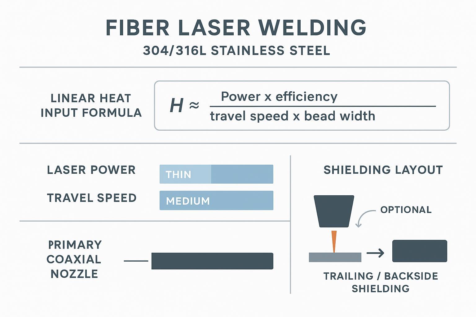
Think of linear energy as the amount of heat delivered per unit length. For laser welding, a simplified concept is:
H ≈ (Power × efficiency) / (travel speed × effective bead width)
The goal is full penetration (or the specified depth) with minimal linear energy—achieved by dialing sufficient power at higher speeds, maintaining a stable focus/spot, and avoiding unnecessary dwell. That’s the practical bridge between the mechanism and shop‑floor knobs.
Use higher travel speeds and the smallest spot that still gives the required penetration to confine the heated volume. If you must slow down for fit‑up constraints, compensate by adjusting focus or using conduction mode on thin gauges to keep the HAZ small.
Focus, spot size, and shielding gas
Power density is governed by focus position and spot size. Slight defocus can smooth the melt pool but increases the effective spot, which can broaden the HAZ. For 304/316L, coaxial argon shielding is common, with optional helium mixes to improve heat transfer and stabilize the plume in some setups. Trailing and backside shielding protect the hot metal from oxidation, which helps preserve chromium‑rich passive films and reduces post‑weld cleaning burden. For clear, accepted practices on weld cleaning and passivation after fabrication, consult the ASTM A380 practice for cleaning/descaling/passivation of stainless assemblies.
Filler metals and grade selection
Favor L‑grades (304L/316L) to limit carbon available for carbide formation; match filler to service requirements and design code. Stabilized grades (321/347) can be chosen where repeated thermal exposures are expected.
Oceanplayer fiber laser systems support stable power/speed control and shielding integration to help maintain consistent thermal cycles.
Post-weld treatments
Austenitic stainless strategies
When fabrication constraints, heavy sections, or service severity raise the probability of sensitization, a full solution anneal (for example, ~1040–1150 °C followed by rapid quench per alloy guidance) can dissolve chromium carbides and restore corrosion resistance. In many thin‑gauge laser welds, careful parameter control plus diligent surface finishing is sufficient. Regardless, remove heat tint, clean, and chemically passivate before corrosion testing; the Nickel Institute’s fabrication guidelines and ASTM A967 provide accepted approaches for chemical passivation media and verification methods.
Stabilized grades (321/347)
Titanium‑ or niobium‑stabilized grades tie up carbon as stable carbides, preserving chromium in solution during thermal cycling. In typical service, these grades reduce the need for PWHT to mitigate IGC—though cleanliness, shielding, and finishing remain critical. TWI’s notes on good stainless welding practice summarize why stabilization strategies are effective and when they’re appropriate.
Nickel alloys and special cases
Solid‑solution nickel alloys (e.g., 600/625/825) are generally not dependent on PWHT to regain corrosion resistance, but weld heat input, thermal history, and surface condition still matter. In aggressive chemistries, select ASTM G28 for IGC screening and pair with microanalysis to separate metallurgical effects from surface contaminants. Finish to specification before testing to avoid conflating heat tint with genuine susceptibility.
QA and verification
Test planning and acceptance
Create a plan that proves the claim, not just the process. A practical sequence for 304/316L includes:
- Coupon location and orientation: extract specimens that traverse weld metal, fusion line, and multiple offsets into the HAZ.
- Screening: run ASTM A262 Practice A (oxalic etch) to quickly flag ditch structures; document photomicrographs.
- Confirmation: where needed, run Practice C (Streicher) or Practice E for quantitative/visual confirmation, per project procedures.
- DL‑EPR mapping: quantify DOS across weld/HAZ to correlate with parameters and shielding quality.
- Optional CPT: run ASTM G150 to confirm localized corrosion resistance once cleaning/passivation are complete.
Define acceptance logic in your welding procedure/QA plan—e.g., “No ditch structures in Practice A at specified magnification; if present, confirm via Practice C/E and initiate corrective actions.” Keep it standards‑referenced and project‑specific.
Microanalysis and mapping
Use etched cross‑sections at the fusion boundary to survey carbide precipitation and grain‑boundary condition. Where necessary, apply SEM/EDS or EPMA line scans to observe chromium depletion profiles. Tie microstructural observations back to parameter changes (power/speed/focus) and shielding effectiveness. This triangulation—parameters → microstructure → test outcome—is what builds confidence that your laser welding intergranular corrosion control is robust in production.
Surface finishing and passivation
Surface condition can mask or mimic metallurgical effects. After weld, remove oxides/heat tint and embedded iron, then passivate chemically following ASTM A967. For practical cleaning/descaling sequences and verification checks (e.g., water‑break tests), rely on the procedures summarized in ASTM A380. Consider CPT (ASTM G150) on representative finished specimens in high‑consequence applications as a final guardrail.
Conclusion
Laser welding suppresses intergranular corrosion primarily by compressing the thermal cycle: less heated volume, faster transit through the sensitization range, and a narrower HAZ than MIG. That mechanistic advantage pays off when parameters, focus/spot, and shielding are disciplined—and when finishing restores the passive film before service. Put it into practice by targeting low linear energy with adequate penetration, selecting appropriate alloys/fillers, applying PWHT only when warranted, and verifying outcomes with ASTM A262, DL‑EPR, and (where relevant) G150. Do this consistently, and you’ll turn the thermal‑cycle advantage into durable, standards‑defensible performance.
References and further reading (selective, canonical sources mentioned inline):
- ESAB University overview of process differences highlighting energy concentration and HAZ behavior: see the article “Laser welding vs traditional welding.” https://esab.com/ca/nam_en/esab-university/articles/laser-welding-vs-traditional-welding/
- Nickel Institute technical overview on high‑temperature characteristics and sensitization context in austenitic stainless steels. https://nickelinstitute.org/media/4657/ni_aisi_9004_hightemperaturecharacteristics.pdf
- TWI explanation of the heat‑affected zone and implications for properties. https://www.twi-global.com/technical-knowledge/faqs/what-is-the-heat-affected-zone
- ASTM G150 method page for electrochemical CPT testing. https://www.astm.org/g0150-18.html
- ASTM A380 practice for cleaning, descaling, and passivation of stainless steel. https://www.astm.org/a0380_a0380m-17.html
- Corrosionpedia explainer on ASTM A262 practices and interpretations. https://www.corrosionpedia.com/6-tests-to-assess-intergranular-corrosion-using-astm-a262/2/7430