Introduction
A tire vulcanization mold is the precision tooling that imparts final geometry, tread pattern, sidewall markings, and bead profiles while the green tire cures under heat and pressure. Each element of the mold influences quality (tread fidelity, uniform cure), throughput (cycle time/takt), and total cost of ownership (maintenance uptime and lifespan). Architecture choices set the stage for demolding behavior and venting options, while component materials, finishes, and tolerances govern durability and flash control. Thermal circuits decide how evenly and how quickly the tire reaches the target cure—often the single biggest lever for cycle time.
In this guide, we compare two-piece and segmented mold architectures; break down core tire mold components; detail venting and ejection; go deep on heating/cooling circuits and cure uniformity; and close with materials, surface finish targets, and tolerance/fit guidance. Along the way, you’ll get practical numbers, inspection checkpoints, and maintenance tips for reducing downtime.
Key takeaways
- Thermal system design (media, circuit topology, and sensorization) is the strongest driver of cure uniformity and cycle time among tire mold components.
- Architecture matters: two-piece molds are simpler and cheaper; segmented molds unlock complex treads but demand tighter alignment and vent control.
- Venting must evacuate gases fast without creating flash; cleanliness of micro-vents and vent pins dominates defect rates and maintenance cadence.
- Build for serviceability: quick-change segments/pins and planned ultrasonic/dry-ice/laser cleaning reduce downtime more than any single coating choice.
- Surface finish and coatings balance release, wear, and appearance; set different targets for treads vs sidewalls.
- Fit, concentricity, and runout targets protect uniformity; verify with CMM/roundness and on-rig TIR checks after heat-soak.
Mold architectures
Two-piece design
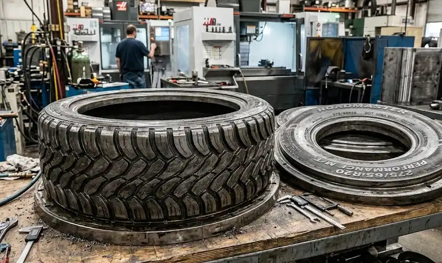
Two-piece tire molds split along a single parting line. They’re straightforward to manufacture and maintain, with fewer moving interfaces and simple opening/closing motion. For moderate tread depth and fewer negative features, two-piece designs can deliver excellent fidelity and fast maintenance turnaround. However, aggressive or highly undercut tread blocks increase demolding risk and may force compromises (reduced feature depth, added draft) or more complex ejection assistance.
In practice, venting relies on parting lines, micro-vents along fine features, and discrete vent pins at last-fill zones. Ejection is typically simple—once halves separate, press-actuated lift-out or pin assist clears the cured tire. Cost and lead time are usually lower than segmented builds, but capability for extreme tread geometries is limited. For a neutral overview of mold types and terminology used across PCR/TBR/OTR applications, see the industry’s association glossary entry on segmented molds and supplier explainers such as the concise taxonomy in the KDMFAB article.
According to the Tire Industry Association’s definition of segmented molds in its glossary, segmented constructions are designed specifically to release complex tread features by coordinated retraction, highlighting the architectural distinction and why two-piece tools are preferred for simpler patterns. See the association’s reference in the entry titled Segmented Mold.
Segmented design
Segmented molds use multiple radial segments (commonly seven to ~ten) that retract to free complex tread geometries without scuffing. They enable deep/negative features and fine sipes while protecting demold quality. The trade-off is increased design and maintenance complexity: segment alignment, gap control, and actuation sequencing require tight tolerances and robust mechanisms.
Engineers often place and align vents across segment borders to avoid dead zones, then coordinate radial retraction before lift-out to protect complex features. Modular maintenance can be an advantage—swapping a single segment plate can cut downtime if the mold is designed for access.
Selection trade-offs
Choose architecture by tread complexity, production mix, maintenance philosophy, and budget. If tread features are moderate and uptime depends on quick clean/turn cycles, two-piece can be optimal. If pattern fidelity on aggressive treads is non-negotiable, segmented designs pay off with better demolding and vent placement flexibility—provided alignment and gap control are engineered well.
Core tire mold components
Mold base and alignment
The base locates tread segments/rings, sidewall plates, and bead rings while transmitting press loads. Alignment features—tapered seats, keys, reference cylinders, and dowels—control concentricity and runout. Many manufacturers target assembled mold Total Indicator Runout (TIR) on the order of ≤0.1 mm, verified by CMM and dedicated runout rigs, to protect uniformity. Guidance on achieving tight TIR via datum strategy and single-setup manufacturing appears in a 2024 machining whitepaper by GF Machining Solutions in its tire mold manufacturing paper, which documents TIR control and alignment workflows.
Establish clear primary/secondary/tertiary datums that persist from machining to assembly and inspection, and capture thermal growth in fit stack-ups so alignment holds after heat-soak. Provide service access to fasteners and alignment features to shorten teardown/clean cycles.
Reference: See the discussion of TIR targets and precision alignment in the GF Machining Solutions tire mold manufacturing whitepaper (2024), which outlines practical verification strategies and on-rig checks.
Tread segments
Segments carry the tread geometry and integrate venting features. Common materials include P20 or H13 tool steels for wear resistance, with selective use of aluminum-bronze inserts for heat conduction where practical. Segments often “float” slightly on biasing elements to avoid binding during thermal expansion and retraction sequences—an approach seen historically in segmental mold mechanisms.
Integrate micro-vents and vent-pin counterbores near last-fill features and sharp edges, protect fine sipes with edge radiusing and finish control, and reference each segment to common datums. Use CMM to ensure cumulative errors don’t stack around the circumference.
Sidewall plates and bead rings
Sidewall plates define cosmetic surfaces and markings; bead rings form bead seats and protect dimensional accuracy at the tire-bead interface. Sidewalls typically require finer finishes for appearance and release, while bead ring geometry demands tight tolerances to avoid uniformity issues. Control parting lines to minimize flash, specify textures where they aid release, and use harder coatings in high-wear ejection paths.
Venting and ejection
Venting strategies
Venting must let gases escape rapidly while preventing rubber ingress that causes flash. Fundamental mold-venting principles apply: provide sufficient flow paths at last-fill regions and tight cavities, then keep those paths clean and self-limiting under pressure. The primer Back to Basics on Mold Venting explains general principles that translate to elastomer curing with validation for your compound and press conditions.
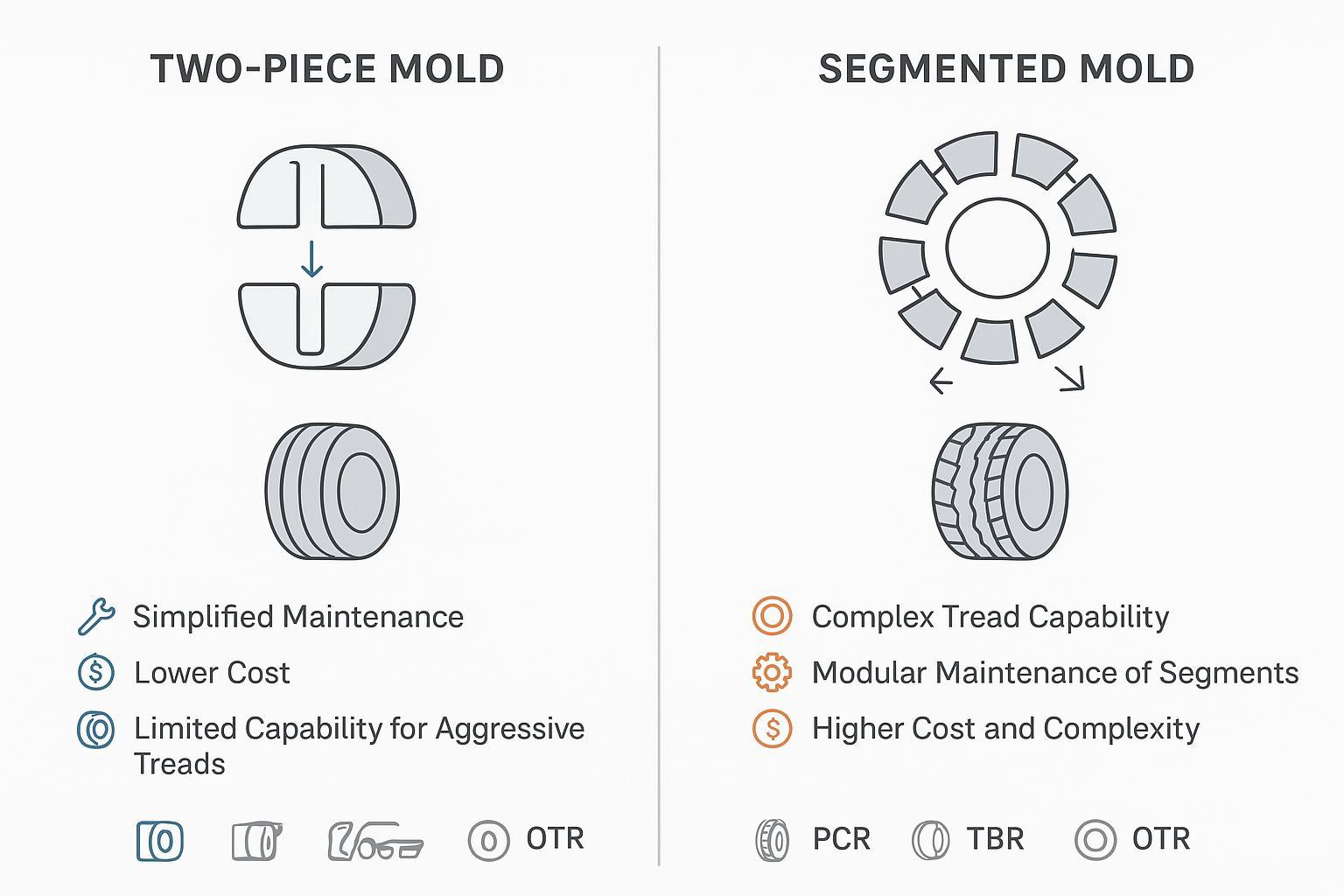
Common tire-mold implementations include micro-vent slits along edges of fine features (a starting heuristic is ~0.02 mm slit width; validate via short-shots and bluing) and vent pins/inserts with stepped geometry that self-occlude at pressure. A representative tire mold patent (WO2016106190A1) documents practical vent insert dimensions and through-holes in the 0.050–0.25 in range, with counterbores for replaceable inserts and small-end pin diameters often in the 0.030–0.125 in envelope—useful as design envelopes before tuning via DoE. Segment gap vents at controlled clearances can also help; align across segments to avoid stagnant pockets.
Placement should densify vents at sharp tread edges/knobs and predicted last-fill zones, and align vent patterns across adjacent segments. Verify by short-shots, airflow checks, and defect mapping.
Maintenance reality: Clogged micro-vents and spring-vents drive blisters, burns, and flash. Plan for rapid cleaning access and standardized inspection.
Ejection mechanisms
Two-piece molds typically rely on press-actuated opening with optional ejector pins. Segmented molds coordinate radial retraction of segments before lift-out to protect complex features. Advanced cells may add robotics for unload, but the press sequence remains the primary control. Keep ejector lubrication clean and consistent, and limit contact on cosmetic sidewall surfaces.
Flash control and cleaning
Design for self-closing vents (stepped pins, slit geometries that seal under pressure) and maintain sharp, flat parting lines. Coatings with low adhesion and good wear resistance help, but cleanliness has the larger impact on day-to-day flash trends.
Downtime-focused cleaning methods include dry ice blasting (in-situ, no media residue; effective on general fouling—avoid direct impingement on delicate edges and thin coatings), ultrasonic cleaning for spring-vents/vent pins (cavitation removes internal fouling when combined with appropriate chemistry and temperature), and laser cleaning (precise, non-contact removal on textured surfaces; validate energy density on coupons; ensure enclosure/filtration and eye safety). For a neutral overview of ultrasonic cleaning for spring-vents, see the supplier note on tire molds from Inoxcast; for dry-ice and laser methods, see application explainers by Cold Jet and EV Laser.
Maintenance SOP (quick checklist):
- Lock-out/tag-out or use enclosed cleaning systems; ventilate for CO2 when dry-ice blasting.
- While warm if method allows, dry-ice clean tread and sidewall surfaces; protect fine edges.
- Remove and batch-clean spring-vents/vent pins ultrasonically; rinse/dry; lightly oil if specified.
- Inspect micro-vent slits under magnification; deblock with non-marring tools; verify airflow with low-pressure air.
- If using laser, set energy within coating-safe window; capture particulates with filtration.
- Final visual/airflow/leak checks; log hours since last clean and defect trends.
Short case insight: Running a high–carbon black PCR tread, one plant saw blister defects spike after 36–48 production hours. Moving spring-vents to a weekly ultrasonic schedule and adding a shiftly micro-vent inspection cut defect-related scrap while trimming unplanned stoppages. Your cadence will vary—track vent pressure drop/airflow and defects vs hours to tune intervals.
For fundamentals of venting applicable to rubber tooling, see the Plastics Technology primer Back to Basics on Mold Venting (2019, evergreen). For tire mold–specific vent assemblies and dimensions, review the patent Tire mold and vent insert WO2016106190A1.
Thermal systems
Heating media and circuits
Cure uniformity and takt time hinge on how you heat the mold. Common media include steam, superheated water (closed-loop), thermal oil, and electric elements. The circuit topology matters as much as the medium. Parallelized, zoned circuits enable region-specific control (e.g., upper vs lower plates, shoulder zones), improving uniformity; series-only paths risk hot-first/cold-last regions and slower overall cure. Baffles/flow guides and well-designed manifolds eliminate dead zones and improve temperature stability. An engineering article on press manifold redesign (Extrica, 2024) documents how equalized distribution reduces gradients and stabilizes cure—principles that transfer to tire molds with proper validation.
Sensorization is your feedback loop: place thermocouples near historical cold spots (shoulder/sidewall transitions) and monitor supply/return delta-T to balance flows. Lab standards that govern rubber cure measurements—such as ASTM D2084 (oscillating disk rheometer) and ISO 3417—don’t prescribe production sensor placement, but they do underscore the importance of calibrated, accurate temperature control.
Action checklist for circuit design (keep it short and focused):
- Use parallel, zoned supplies with balanced lengths and independent valves.
- Add baffles/guide pipes to equalize flow; avoid blind branches.
- Instrument each zone with at least one cavity-adjacent sensor plus a supply/return reference; trend delta-T.
- Define an internal intra-tread delta (often <5–10 °C depending on compound) and tune until you hit it.
For a concise overview of vulcanization media and circuits, see the GreyB Xray compilation on presses and media, which summarizes common heating approaches and control considerations.
Cooling and conformal channels
Cooling paths (water/glycol) shorten handling temperature and stabilize repeatability. Where manufacturing allows, conformal or contoured channels in bases/large segments improve uniformity and can reduce pressure drop relative to straight gun-drilled paths. Peer-reviewed polymer tooling literature reports measurable uniformity and cycle improvements with conformal cooling; treat these results as directional and validate under tire curing conditions before committing.
Balance flow with even manifolds and consider flow meters on returns to spot starving zones. Keep channel diameters and lengths consistent inside a zone, and insulate exposed supply runs.
Cure uniformity control
Define cure uniformity using in-cavity or near-surface temperature traces correlated to rheometer curves for the compound. Monitor shoulder vs centerline delta during soak/hold, per-zone supply/return delta-T, and time-to-spec at critical surfaces after press close. Then tune: map temperatures around the circumference, increase local flow or zone setpoints at cold spots, add or reposition baffles, and if gradients persist, split the zone or add a parallel feed.
A truck-tire line with chronic shoulder under-cure reduced intra-tread delta from about 12 °C to around 5 °C by re-plumbing upper-plate circuits into two parallel zones with added baffles, and by relocating a thermocouple near the shoulder. Cycle time dropped several percent without increasing defects—evidence that better distribution pays back quickly.
Materials and tolerances
Material choices and coatings
Choose materials by balancing machinability, wear, corrosion resistance, and thermal conductivity. P20 offers good machinability and moderate wear with ~25–30 W/m·K conductivity. H13 brings higher wear resistance and toughness near ~25 W/m·K but needs corrosion protection in steam service. Stainless grades provide strong corrosion resistance at ~15–20 W/m·K and may lengthen cycle unless compensated with thermal design. Aluminum bronze conducts heat faster (~50–70 W/m·K) and reduces mass but is softer—use selectively.
Coatings and surface treatments extend life and improve release. Electroless nickel composites and hard thin films increase wear/corrosion resistance and lubricity when specified for steam exposure. Fluoropolymer topcoats reduce adhesion; control thickness to avoid masking micro-features and adding thermal resistance. Semi-permanent water-based release agents can reduce fouling and protect during storage when activated properly per the technical data sheets.
For comparative materials data and coating behaviors, see the Encore Metals tool steel manual for thermal and mechanical properties, Magnaplate’s molds-and-dies coating overview for wear/corrosion improvements, and Teflon industrial coating pages for release characteristics.
Surface finish targets
On tread surfaces, prioritize fidelity on micro-features and sipes with fine finishes and protected edges to minimize mechanical interlock and sticking. Sidewalls are driven by aesthetics (matte to glossy); uniform textures can ease demold and mask minor scuffs. Validate finish choices using representative coupons or a single segment before committing the full set. Application notes in additive tooling and supplier pages show the order of magnitude for texture spacing and achievable micro-feature fidelity; use them as directional context rather than prescriptive specs.
Fit, concentricity, runout
Geometric control safeguards uniformity and repeatability. Target assembled TIR on the order of ≤0.1 mm when feasible, confirm on a dedicated concentricity/runout rig after assembly and after heat soak, and use CMM to verify segment datum features and assembled ring geometry. For larger diameters, a laser tracker can speed verification. Record thermal growth allowances and re-check after major maintenance or segment swaps.
Conclusion
Getting tire mold components right is about disciplined decisions: pick the architecture that matches tread complexity and your maintenance philosophy; design vents that move gas quickly without inviting flash; and, above all, engineer heating/cooling circuits and sensors that deliver cure uniformity within your spec at the shortest safe cycle. Materials, finishes, and tight fits keep that performance stable over thousands of cycles.
Next steps for engineers: Align vent geometry and placement to compound and last-fill mapping, then validate with short-shots, bluing, and airflow checks. Revisit circuit topology and sensor placement; set an explicit intra-tread temperature delta target and tune until you hit it. Finally, build a maintenance plan that standardizes quick visual checks each shift, ultrasonic cleaning cadence for vents, and periodic dry-ice or laser deep cleans—all logged against defect trends to cut downtime.
—
Inline sources cited with descriptive anchors in context:
- The Tire Industry Association’s Segmented Mold glossary entry describes segmented architecture and demolding intent: https://www.tireindustry.org/pub/?id=C5A822A7-1866-DAAC-99FB-7EC6C790EE9B
- A supplier taxonomy summarizes common tire mold types and their applications: https://kdmfab.com/tire-mold/
- GF Machining Solutions details TIR targets and alignment workflows in its tire mold manufacturing whitepaper (2024): https://www.gfms.com/content/dam/gfms/pdf/industries/automotive/en/tire-mold-whitepaper.pdf
- Plastics Technology’s Back to Basics on Mold Venting (2019, evergreen) explains venting fundamentals transferable to elastomer tools: https://www.ptonline.com/articles/part-1-back-to-basics-on-mold-venting
- Patent WO2016106190A1 documents a tire mold with vent inserts and practical dimension ranges: https://patents.google.com/patent/WO2016106190A1/en
- An Extrica engineering article (2024) shows how manifold redesigns improve flow/temperature uniformity: https://www.extrica.com/article/24625
- GreyB’s vulcanization presses overview compiles common heating media and circuit considerations: https://xray.greyb.com/tires/vulcanization-presses
- ASTM D2084 (oscillating disk rheometer) underscores calibrated temperature control for rubber cure measurements: https://www.astm.org/d2084-19a.html
- Materials and coatings references: Encore Metals tool steel data (https://www.encoremetals.com/wp-content/uploads/2024/03/Encore-Metals-Product-Manual_2016APR15.pdf), Magnaplate molds-and-dies coatings (https://www.magnaplate.com/pdfs/brochures/molds_and_dies.pdf), and Teflon industrial coatings (https://www.teflon.com/en/products/coatings)