The mold itself typically accounts for 50–70% of total project cost in injection molding — yet most teams don’t seriously address cost reduction until tooling quotes come back higher than expected. That’s backwards. The most effective way to reduce injection mold cost is to embed cost-conscious decisions into every phase: part design, mold material selection, cavity strategy, and manufacturer partnership. This guide breaks down each lever with specific, actionable detail so product managers, engineers, and procurement specialists can cut tooling spend without compromising part quality or production reliability.
Why Injection Mold Cost Matters More Than You Think
Most teams fixate on per-part pricing when evaluating injection molding quotes. That’s a mistake. The mold — the steel or aluminum block that shapes every single unit — is where the real financial leverage sits. A poorly optimized mold doesn’t just cost more upfront; it creates a compounding cost penalty across every production run through longer cycle times, higher scrap rates, and more frequent maintenance shutdowns.
Break down a typical injection molding project and you’ll find four primary cost drivers:
- Tooling (mold fabrication): 50–70% of initial project investment. Complex geometries, tight tolerances, and premium steel grades push this higher.
- Material (resin): 20–30% of per-part cost. Wall thickness and runner design directly determine how much plastic each shot consumes.
- Cycle time: Every second added to a molding cycle multiplies across thousands or millions of parts. A 5-second reduction on a 30-second cycle represents a 17% throughput gain.
- Post-processing: Secondary operations like trimming, painting, or assembly add labor and handling costs that well-designed molds can minimize or eliminate.
Here’s what makes injection mold cost reduction so powerful: savings compound. Reduce mold complexity and you simultaneously shorten machining time, simplify cooling channel design, improve cycle time, and lower maintenance frequency. A single design simplification that saves $3,000 on tooling might also shave 2 seconds off cycle time — worth another $8,000–$15,000 over a 500,000-unit run.
The teams that consistently hit cost targets aren’t the ones negotiating harder on mold quotes. They’re the ones making smarter decisions at the design stage, choosing appropriate mold materials for their volume, and working with manufacturing partners who catch expensive mistakes before steel gets cut.

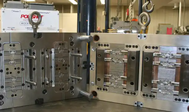
Injection molding cost breakdown chart showing tooling as the largest expense category
Applying Design for Manufacturing Early to Eliminate Costly Revisions
DFM for injection molding is not a checkbox at the end of the design process. It’s a cost-prevention discipline that belongs at the very beginning — during concept sketches, before anyone opens CAD software for detailed modeling.
Why does timing matter so much? Because the cost of design changes follows an exponential curve. A draft angle correction during the concept phase costs nothing — it’s a line on a sketch. The same correction after mold steel has been ordered and machining has started? That’s a $5,000–$25,000 engineering change order (ECO), plus 2–4 weeks of delay. According to research published by the National Institute of Standards and Technology (NIST), the cost of correcting a design flaw increases by roughly 10x at each subsequent development stage.
Early DFM analysis flags the issues that silently inflate mold costs:
- Insufficient draft angles that require side-actions or lifters in the mold, adding $2,000–$10,000 per feature.
- Undercuts that demand complex sliding cores or collapsible mechanisms — sometimes doubling mold fabrication time.
- Non-uniform wall thickness that causes sink marks, warpage, and extended cooling times, leading to higher scrap rates and longer cycles.
- Overly tight tolerances on non-critical dimensions that force the mold shop to use slower, more expensive machining processes.
The most expensive sentence in product development is “we’ll fix it in tooling.” Every feature that gets designed without manufacturing constraints in mind becomes a cost multiplier downstream. Product teams that run DFM analysis during initial concept review — not after design freeze — typically see 15–30% lower tooling costs compared to teams that treat DFM as a late-stage formality.
This isn’t theoretical. It’s arithmetic. Fewer mold features means less CNC machining time, fewer EDM operations, simpler mold assembly, and faster first-article approval. The design stage is where you have the most leverage and the lowest cost to make changes. Use it.
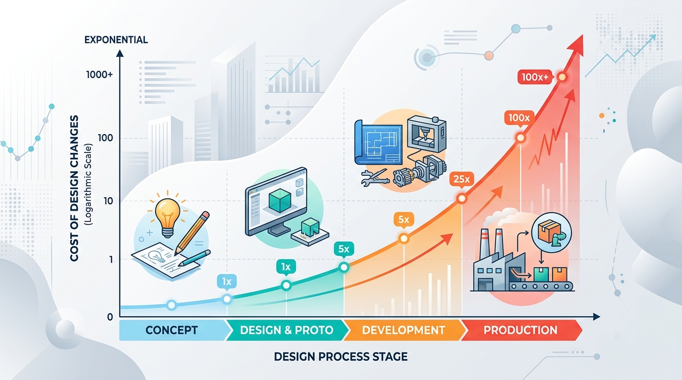
Design change cost curve showing exponential increase from concept through tooling to production
Key DFM Checkpoints Every Product Team Should Follow
Knowing that DFM matters is one thing. Integrating it into your actual workflow — with specific gates that prevent cost-inflating designs from advancing — is where results happen. Here’s a practical checkpoint sequence that works across industries, from consumer electronics enclosures to industrial components.
Checkpoint 1: Initial CAD Review (Before Design Freeze)
Run a manufacturability screening on the 3D model. At this stage, you’re looking for obvious violations: walls thinner than 0.8 mm or thicker than 4 mm without coring, sharp internal corners below 0.5 mm radius, and features that clearly require side-actions. Most CAD platforms have basic draft analysis tools built in. Use them. This 30-minute review catches about 60% of the issues that would otherwise become expensive mold modifications.
Checkpoint 2: Mold Flow Simulation
Before any tooling quote goes out, run a mold flow analysis. Software like Autodesk Moldflow simulates fill patterns, cooling behavior, weld line locations, and shrinkage. This isn’t optional for cost-conscious projects — it’s essential. Mold flow analysis typically costs $500–$2,000 but regularly prevents $10,000+ in mold rework by identifying gate placement issues, air traps, and cooling imbalances before steel is cut.
Checkpoint 3: Tolerance Review
Go through every tolerance callout on the drawing. Ask one question for each: does this dimension actually need to be this tight? Tolerances tighter than +/- 0.05 mm on non-mating, non-functional surfaces force mold makers to use precision grinding and polishing operations that add significant cost. Relaxing non-critical tolerances to +/- 0.1 mm or wider can reduce mold machining time by 10–20%.
Checkpoint 4: Pre-Tooling Design Review with Manufacturer
Share the final design with your mold manufacturer before placing the tooling order. A good manufacturer will review gate locations, parting line placement, ejection strategy, and cooling layout — and suggest modifications that simplify the mold without affecting part function. This collaborative review is where experienced tooling partners earn their value. Skip it, and you’re gambling that your design is perfectly optimized. It almost never is.
Pro tip: Document every DFM checkpoint with a simple pass/fail log. When someone on the team asks “why does this part cost less than our last project?” you’ll have the answer — and a repeatable process for the next one.
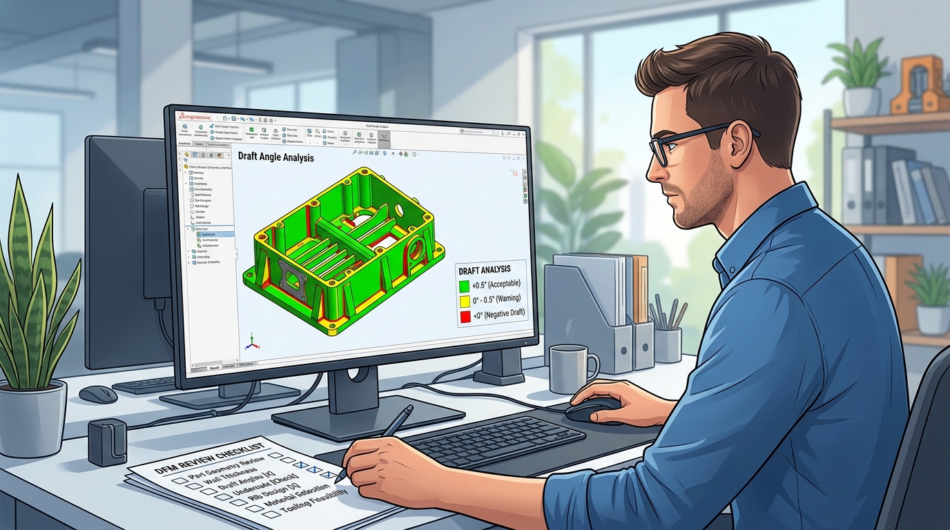
Design for manufacturing checklist being reviewed alongside CAD draft analysis on screen
Simplifying Part Geometry and Wall Thickness to Drive Down Tooling and Cycle Costs
Injection molding design optimization starts with a blunt question: does this feature actually need to exist?
Every rib, boss, snap-fit, and cosmetic detail on a part translates directly into machining operations on the mold. Remove a feature from the part and you remove the corresponding pocket, electrode, or insert from the tool. The relationship is linear and predictable.
Geometry Simplification That Pays Off
Consider these specific changes and their typical cost impact:
| Design Change | Mold Cost Reduction | Cycle Time Impact |
|---|---|---|
| Eliminate one side-action (undercut removal) | $3,000–$12,000 saved | Minimal |
| Consolidate two separate parts into one | Eliminates one entire mold ($15,000–$80,000) | May increase slightly |
| Standardize corner radii to 2–3 sizes | $1,000–$3,000 saved (fewer tool changes) | No impact |
| Remove cosmetic texture from non-visible surfaces | $2,000–$8,000 saved (no EDM texturing) | No impact |
| Replace snap-fits with ultrasonic weld joints | $1,500–$5,000 saved (simpler mold) | Adds post-process step |
Part consolidation deserves special attention. If your assembly has two injection-molded parts that bolt or snap together, ask whether they could be a single part. Eliminating one mold entirely is the most dramatic cost reduction available — you’re not optimizing a tool, you’re deleting it.
Wall Thickness: The Hidden Cost Multiplier
Wall thickness affects everything. Thicker walls consume more resin per shot, require longer cooling times (cooling is typically 60–70% of total cycle time), and increase the risk of sink marks and internal voids that drive up scrap rates.
The sweet spot for most commodity resins (ABS, PP, PE) sits between 1.2 mm and 3.0 mm. Going from 3.0 mm to 2.0 mm on a medium-sized part can cut cycle time by 25–35% and reduce material consumption by roughly a third. On a 200,000-unit annual run, that geometry change alone might save $20,000–$40,000 per year in combined material and machine time.
Uniform wall thickness matters just as much as absolute thickness. Variations greater than 25% between adjacent sections create differential cooling rates, leading to warpage, sink marks, and dimensional instability. Coring out thick sections and adding ribs (at 50–60% of nominal wall thickness) maintains structural rigidity while keeping the walls uniform and the cycle fast.
One common mistake: designers add wall thickness for strength when ribs would be more effective. A 2 mm wall with properly designed ribs is stiffer than a 3.5 mm solid wall — and it molds faster, uses less material, and produces fewer defects.
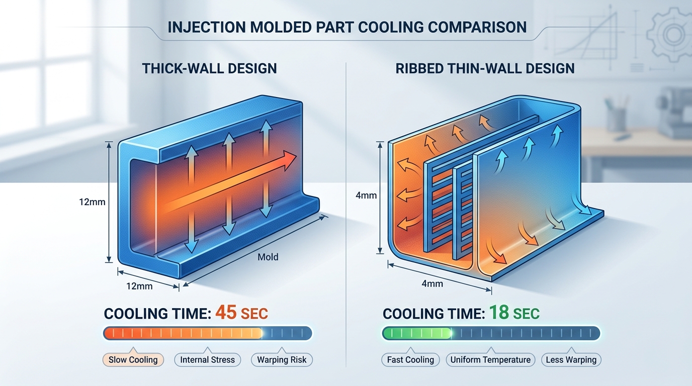
Cross-section diagram comparing thick solid wall versus thin ribbed wall design in injection molding
Choosing the Right Mold Material Based on Production Volume and Budget
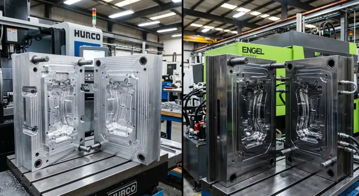
Mold material selection is one of the highest-impact decisions in any injection molding project, and it’s frequently mishandled. Teams either default to hardened steel for everything (overspending on low-volume projects) or choose aluminum to save money without understanding its limitations (risking premature tool failure on high-volume runs).
The right choice depends on three variables: expected lifetime volume, part complexity, and required surface finish.
Aluminum Molds: Fast, Affordable, and Underrated
7075-T6 aluminum tooling has come a long way. Modern aluminum molds handle 10,000–100,000 shots reliably, and some high-grade aluminum tools push past 200,000 with proper maintenance. The advantages are significant:
- 40–60% lower fabrication cost compared to P20 or H13 steel molds
- Lead time reduced by 2–5 weeks — aluminum machines 3–5x faster than tool steel
- Better thermal conductivity (aluminum conducts heat roughly 5x faster than steel), which can reduce cycle times by 15–25%
- Easier modifications — design changes on aluminum tools cost less and take less time
The limitations are real, though. Aluminum can’t hold the same fine textures or ultra-tight tolerances as hardened steel. It’s more susceptible to damage from glass-filled or abrasive resins. And for parts with thin steel features (like deep ribs or narrow shutoffs), aluminum simply doesn’t have the wear resistance to maintain dimensions over long runs.
Steel Molds: The Long-Game Investment
For production volumes above 250,000 units, hardened steel (H13, S136, or equivalent) is almost always the right call. The higher upfront cost — typically $25,000–$150,000+ depending on part size and complexity — amortizes across a larger number of parts, driving per-unit tooling cost below what aluminum could achieve.
Steel mold grades and their typical applications:
| Steel Grade | Hardness (HRC) | Best For | Expected Tool Life |
|---|---|---|---|
| P20 (pre-hardened) | 28–34 | Medium-volume, non-abrasive resins | 250,000–500,000 shots |
| H13 (hardened) | 48–52 | High-volume, abrasive/glass-filled resins | 500,000–1,000,000+ shots |
| S136 (stainless) | 48–52 | Medical, optical, corrosion-prone resins (PVC) | 500,000–1,000,000+ shots |
| NAK80 (pre-hardened) | 38–42 | High-polish cosmetic parts | 300,000–500,000 shots |
The Decision Framework
Stop thinking about aluminum vs. steel as a quality decision. It’s a volume decision. Under 50,000 lifetime parts? Aluminum almost certainly wins on total cost. Between 50,000 and 250,000? Run the numbers — factor in cycle time savings from aluminum’s thermal conductivity against steel’s longer tool life. Above 250,000? Steel, unless the part geometry is simple enough for aluminum to survive.
One scenario that catches teams off guard: launching a new product with uncertain demand. Committing $80,000 to a hardened steel mold for a product that might sell 15,000 units in year one is a terrible bet. Start with aluminum tooling, validate the market, then invest in steel when volume justifies it.
When Soft Tooling and Rapid Prototyping Make Strategic Sense
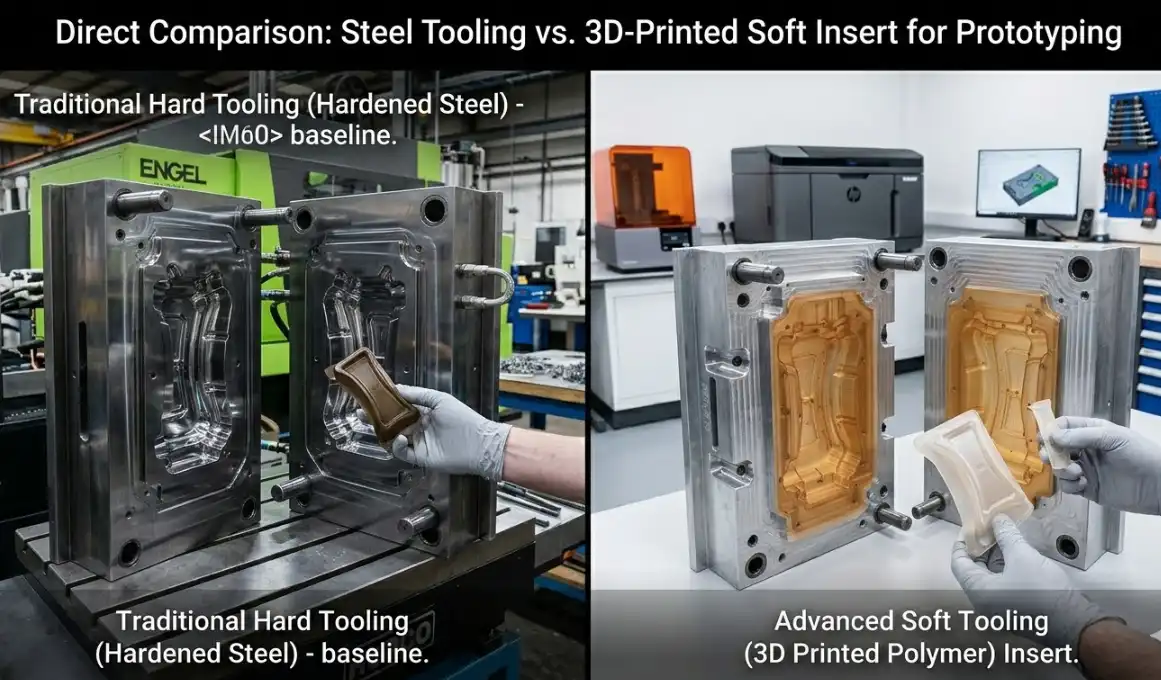
Rapid prototyping isn’t just for startups testing ideas. It’s a legitimate cost-reduction strategy for established manufacturers who need to validate designs before committing to production tooling.
The logic is straightforward: a $3,000–$8,000 prototype mold that reveals a design flaw is dramatically cheaper than discovering that same flaw after spending $60,000 on a production tool. Soft tooling — typically aluminum or even 3D-printed mold inserts — produces parts in the actual production resin, giving you functional prototypes that behave like production parts for fit, form, and basic function testing.
Bridge Tooling: The Middle Ground
Bridge tooling occupies the space between prototype and production molds. These are typically single-cavity aluminum tools built to tighter tolerances than pure prototypes, capable of producing 5,000–50,000 parts. They serve two strategic purposes:
- Market validation: Ship real product to early customers while production tooling is being built. Revenue starts flowing 6–10 weeks earlier.
- Design iteration: If customer feedback requires changes, modifying a bridge tool costs a fraction of reworking a hardened steel production mold.
Teams that skip prototyping to “save time” often end up spending more of both time and money. A study from the Society of Manufacturing Engineers (SME) found that projects using prototype tooling before production tooling experienced 40% fewer ECOs during the production phase. Fewer ECOs means fewer mold modifications, less downtime, and faster time to stable production.
The question isn’t whether you can afford to prototype. It’s whether you can afford not to — especially on parts with complex geometries, tight tolerances, or materials you haven’t molded before.
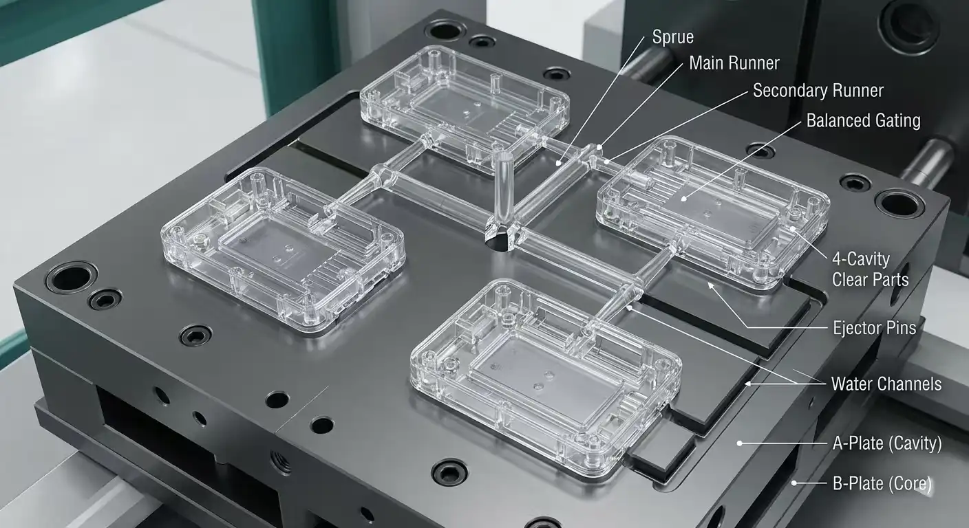
Multi-Cavity Molds — Balancing Upfront Investment Against Per-Part Savings
Multi-cavity molds are the most misunderstood cost lever in injection molding. The pitch sounds irresistible: double the cavities, halve the per-part cost. The reality is more nuanced, and getting the cavity count wrong in either direction wastes money.
The Math That Matters
A single-cavity mold producing a part with a 25-second cycle time yields roughly 1,440 parts per 10-hour shift. A 4-cavity mold with the same cycle time produces 5,760. If your annual demand is 500,000 parts, the single-cavity tool needs 347 shifts (essentially running full-time for over a year), while the 4-cavity tool finishes in 87 shifts.
But here’s where teams get tripped up: that 4-cavity mold doesn’t cost 4x more than the single-cavity version. It typically costs 2–3x more, because the mold base, cooling system, and many components are shared. The per-part tooling amortization drops significantly.
The break-even calculation looks like this:
Break-even volume = (Multi-cavity mold cost – Single-cavity mold cost) / (Single-cavity per-part cost – Multi-cavity per-part cost)
For a part where a single-cavity mold costs $30,000 and a 4-cavity mold costs $75,000, with per-part processing costs of $0.45 (single) vs. $0.15 (quad), the break-even sits at 150,000 parts. Below that volume, the single-cavity tool is cheaper overall. Above it, the 4-cavity tool pulls ahead — and the savings accelerate with every additional unit.
The Downsides Nobody Mentions in Sales Meetings
More cavities introduce real complications:
- Balancing issues: Ensuring all cavities fill simultaneously and produce identical parts requires precise runner balancing. Imbalanced fill leads to dimensional variation between cavities — a quality nightmare.
- Maintenance complexity: If one cavity gets damaged, the entire mold comes offline for repair. Some shops can block off a single cavity and run at reduced capacity, but this isn’t always feasible.
- Longer lead times: A 4-cavity mold takes 2–4 weeks longer to fabricate and validate than a single-cavity equivalent.
- Higher risk of defects: More cavities means more potential failure points. Flash, short shots, and dimensional drift are harder to diagnose and correct.
Optimal Cavity Count Decision Guide
Don’t let a mold maker upsell you to 8 cavities when 2 would serve your volume. Match cavity count to actual demand:
| Annual Volume | Recommended Cavities | Rationale |
|---|---|---|
| Under 50,000 | 1 | Lowest tooling cost; volume doesn’t justify multi-cavity |
| 50,000–200,000 | 2 | Moderate per-part savings; manageable complexity |
| 200,000–500,000 | 2–4 | Significant per-part reduction; run the break-even math |
| 500,000–2,000,000 | 4–8 | Strong ROI if part geometry supports balanced filling |
| Over 2,000,000 | 8–16+ | Per-part cost becomes the dominant factor; justify the complexity |
Family molds — where different parts share a single mold base — deserve a mention here. They save money when multiple related parts have similar shot sizes and cycle requirements. But if the parts differ significantly in volume, wall thickness, or material, family molds create more problems than they solve. Uneven fill, different cooling rates, and quality inconsistencies between cavities can turn a cost-saving idea into a quality control headache.
Material Selection and Resin Optimization Strategies That Lower Total Cost
Mold cost gets all the attention, but resin spend adds up fast — especially on high-volume programs where material represents 20–30% of per-part cost. Smart resin decisions can trim thousands from your annual production budget without touching the mold.
Resin Substitution: Same Performance, Lower Price
Engineers tend to over-specify materials. A part designed in polycarbonate (PC) at $3.50/kg might perform identically in ABS at $1.80/kg if it doesn’t require PC’s heat resistance or optical clarity. Before locking in a resin, challenge every material requirement against actual use conditions.
Common substitution opportunities:
- PC to ABS: When heat resistance above 100C isn’t needed. Saves 40–50% on resin cost.
- Nylon 6/6 to Nylon 6: When the slightly lower heat deflection temperature of Nylon 6 is acceptable. Saves 15–25%.
- Virgin resin to regrind blend: Most non-cosmetic, non-structural parts tolerate 15–25% regrind content without measurable performance loss. This directly reduces material waste and cost.
- Glass-filled grades to mineral-filled: When stiffness (not tensile strength) is the primary requirement. Mineral fillers are cheaper and less abrasive on molds.
Wall Thickness and Material Savings Are the Same Thing
Reducing wall thickness from 3.0 mm to 2.2 mm doesn’t just cut cycle time — it reduces the volume of resin in every single part by roughly 27%. On a part weighing 50 grams at 3.0 mm walls, that’s a 13.5-gram reduction per part. At $2.00/kg for PP resin and 500,000 annual units, that’s $13,500 in material savings per year. From one wall thickness change.
Runner system design matters too. Hot runner systems eliminate the cold runner that gets scrapped or reground on every shot. The upfront cost of a hot runner manifold ($5,000–$20,000) pays back quickly on high-volume programs through reduced material waste and shorter cycle times (no runner to cool).
Don’t overlook colorant strategy either. Pre-colored resin is convenient but costs 10–20% more than natural resin with masterbatch colorant added at the press. For large volumes, the savings from switching to masterbatch dosing are substantial.
How Partnering with an Experienced Manufacturer Prevents Costly Mistakes
The cheapest mold quote is rarely the cheapest mold. This is the lesson that procurement teams learn the hard way — sometimes repeatedly.
An experienced injection molding manufacturer brings value that doesn’t show up on a line-item quote: the ability to identify and prevent problems before they become expensive. Specifically, a capable partner provides three things that directly reduce total project cost.
In-House DFM and Mold Flow Expertise
Manufacturers who run DFM reviews and mold flow simulations as part of their standard quoting process catch design issues that less experienced shops miss entirely. Gate placement that causes visible weld lines on cosmetic surfaces. Cooling channel layouts that create hot spots and extend cycle times. Ejection strategies that leave witness marks on critical surfaces.
These aren’t theoretical problems. They’re the specific issues that generate ECOs, delay production starts, and inflate budgets by 15–30% on poorly managed projects.
Tooling Design Optimization
A manufacturer with deep tooling experience doesn’t just build the mold you designed — they improve it. They’ll suggest parting line adjustments that eliminate side-actions, recommend insert configurations that simplify maintenance, and design cooling circuits that shave seconds off cycle time. These optimizations don’t appear in the initial quote comparison, but they compound across every production run.
Realistic Tolerance and Process Guidance
Inexperienced manufacturers say yes to everything. Experienced ones push back — constructively. When a drawing calls for +/- 0.02 mm on a 200 mm dimension in glass-filled nylon, a good partner will explain that this tolerance is unrealistic for the material and suggest alternatives (tighter tolerance on a datum feature, looser on the overall dimension) that achieve the same functional result at lower cost.
This kind of guidance prevents the worst-case scenario in injection molding: a mold that technically meets spec but can’t produce parts consistently within tolerance, leading to endless sampling rounds, mold adjustments, and production delays.
The manufacturer selection decision should weight technical capability and communication quality at least as heavily as price. A partner who saves you $5,000 on the mold quote but costs you $30,000 in revisions and delays is not a bargain.
Frequently Asked Questions About Reducing Injection Mold Costs
What is the biggest cost driver in injection molding?
Tooling fabrication — the mold itself — is the single largest cost, representing 50–70% of initial project investment. Mold complexity (number of side-actions, surface finish requirements, and tolerance precision) is the primary variable within tooling cost. Simplifying part geometry is the most effective way to reduce this expense.
How much cheaper are aluminum molds than steel?
Aluminum molds typically cost 40–60% less than equivalent steel molds. A mold that would cost $50,000 in P20 steel might cost $20,000–$30,000 in 7075-T6 aluminum. The trade-off is tool life: aluminum molds are reliable for 10,000–100,000 shots, while hardened steel tools last 500,000–1,000,000+ shots.
When should I invest in a multi-cavity mold?
Run the break-even calculation. Generally, annual volumes above 50,000 parts start to justify 2-cavity tooling, and volumes above 200,000 make 4+ cavities worth evaluating. The decision depends on part complexity, cycle time, and how long you expect the product to remain in production.
How does rapid prototyping reduce long-term tooling costs?
Prototype and bridge tooling lets you validate designs with real molded parts before committing $30,000–$150,000 to production molds. Projects that prototype first experience approximately 40% fewer engineering change orders during production, according to SME research. Each avoided ECO saves $5,000–$25,000 in mold modifications and 1–3 weeks of delay.
What is the ROI of a DFM review?
A thorough DFM review typically costs $500–$2,000 when performed independently, and many experienced manufacturers include it in their quoting process at no additional charge. The return is substantial: teams that conduct formal DFM reviews before tooling consistently report 15–30% lower total tooling costs compared to projects where DFM was skipped or performed after design freeze. On a $60,000 mold, that’s $9,000–$18,000 in savings from an investment of under $2,000.
Can I reduce costs by using a cheaper resin?
Yes — but “cheaper” should mean “appropriately specified,” not “inferior.” Many parts are over-engineered with premium resins when a lower-cost alternative meets all functional requirements. Switching from polycarbonate to ABS, for example, saves 40–50% on material cost when the application doesn’t demand PC’s heat resistance or impact strength. Always validate substitutions with mechanical testing before committing to production.
Actionable Cost-Reduction Roadmap for Your Next Injection Molding Project
Strategy without execution is just a wish list. Here’s a prioritized, step-by-step action plan you can apply to your next project — ordered by impact and timing.
Step One: Run DFM Before Design Freeze
Schedule a formal DFM review while the design is still flexible. Check draft angles, wall uniformity, undercuts, and tolerance callouts. If your team doesn’t have in-house DFM expertise, send the 3D model to your tooling partner for feedback before finalizing anything. This single step prevents more unnecessary cost than all other strategies combined.
Step Two: Simplify Geometry Ruthlessly
Challenge every feature on the part. Does that cosmetic texture need to be on all surfaces, or just the visible ones? Can two parts be consolidated into one? Are those snap-fit features necessary, or could adhesive bonding or ultrasonic welding simplify the mold? Remove or simplify every feature that doesn’t serve a critical functional or aesthetic purpose.
Step Three: Optimize Wall Thickness
Target the thinnest uniform wall that meets structural requirements. For most commodity resins, that’s 1.2–2.5 mm. Use ribs for stiffness instead of adding wall thickness. Run mold flow simulation to verify fill behavior at the reduced thickness before committing.
Step Four: Match Mold Material to Volume
Don’t default to steel. If your first-year volume projection is under 50,000 parts and the product lifecycle is uncertain, start with aluminum. You can always invest in steel tooling later when demand is proven. For volumes above 250,000, hardened steel pays for itself through longevity and consistency.
Step Five: Right-Size Your Cavity Count
Calculate the break-even point between single-cavity and multi-cavity options using your actual volume forecast — not the optimistic number from the sales team, the realistic one. Over-investing in cavities you don’t need ties up capital. Under-investing creates capacity bottlenecks that cost more than the mold savings.
Step Six: Evaluate Resin Alternatives
Before production starts, test whether a lower-cost resin meets your performance specifications. Validate with mechanical testing, not assumptions. Consider regrind ratios for non-critical parts and hot runner systems for high-volume programs where runner waste is significant.
Step Seven: Choose Your Manufacturing Partner on Capability, Not Just Price
Request DFM feedback as part of the quoting process. Evaluate how thoroughly each potential partner analyzes your design. The manufacturer who asks the most questions and suggests the most improvements during quoting is usually the one who will cost you the least over the life of the project.
Ready to put this into practice? Before you finalize your next mold design, request a DFM review from a tooling partner with proven injection molding design optimization experience. A single pre-tooling review can identify $10,000–$50,000 in avoidable costs — and it takes less than a week. The best time to reduce injection mold cost is before the first chip of steel gets cut.


