
Introduction
Laser cleaning has moved from pilot curiosity to a mature production process for 2026-era manufacturing. Two shifts led the change: the practical split of roles between pulsed and continuous-wave (CW) fiber sources, and the rise of higher power classes packaged in safety-ready, Industry 4.0–capable cells. The result? Measurable gains in throughput, stable surface quality, cleaner compliance footprints, and lower total cost of ownership when compared with abrasive or chemical methods—especially once you account for consumables and waste handling.
In this guide, we focus on engineer-ready essentials: parameter windows and tuning logic, conservative m²/hr envelopes, verification against recognized surface standards, Class 4 safety and LEV design, automation and traceability integration, and an ROI/TCO model you can adapt to your plant. We use cautious ranges and cite standards where applicable so teams can defend decisions during technical reviews and audits.
Key takeaways
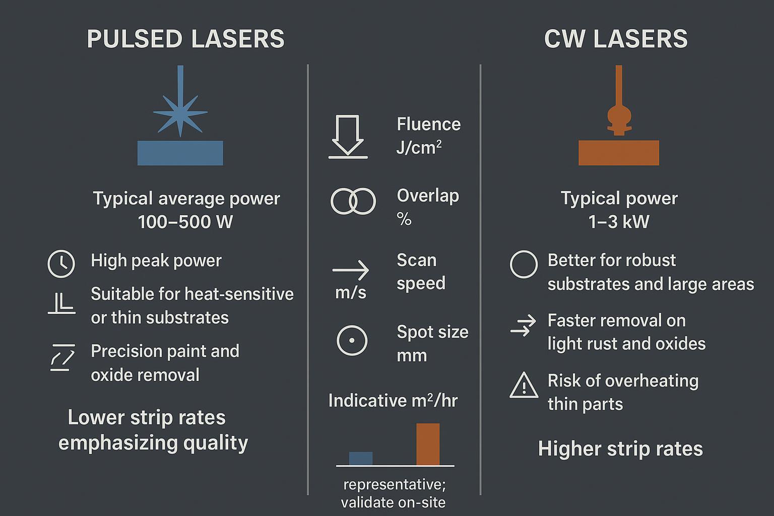
- Pulsed vs CW roles are complementary: pulsed favors heat‑sensitive or thin parts and precision surface goals; CW favors robust substrates and area throughput.
- Performance is governed by fluence, spot size, overlap, and scan speed; treat any published m²/hr as representative and validate on your parts.
- Verification is not optional: align visual grades (e.g., ISO 8501‑1 or AMPP laser ablation guides) with roughness (ASME B46.1/ISO 4287) and, when relevant, adhesion tests.
- Class 4 cells require interlocked enclosures, an LSO program, and LEV with H13/H14 HEPA and appropriate carbon; airflow/ΔP should interlock with emission.
- To maximize laser cleaning ROI, model TCO across CapEx amortization, energy, filter media, labor, and consumables avoided—then run a sensitivity analysis on utilization and strip rate.
Technology overview
Pulsed vs CW roles
Pulsed fiber lasers deliver high peak power with low average heat input, which helps control thermal risk on thin or heat‑sensitive substrates and edges. They are commonly used for precision paint or oxide removal where the substrate must remain nearly untouched. CW fiber lasers deliver high average power for faster removal on robust substrates and large, simple geometries; the trade‑off is a higher risk of thermal loading if parameters are aggressive.
According to vendor‑neutral explainers published in 2024–2025, pulsed is often selected for delicate or high-precision work while CW is selected for speed on sturdy parts. See, for example, the comparisons in the 2025 Wattsan overview and DPLaser’s pulsed vs CW guidance.
Power classes and substrates
- Pulsed: Typical average power spans 100–500 W, with adjustable pulse width and repetition rate. Some higher‑power pulsed systems exist but are less common in cleaning than in welding.
- CW: 1–3 kW is typical for area cleaning on robust metals. These levels support higher traverse speeds but must be paired with appropriate scan strategies and extraction to avoid plume shielding.
Substrates include mild/stainless steel, aluminum, copper alloys, and composites. Aluminum and copper conduct heat rapidly; pulse shaping and lower fluence may be required to avoid substrate effects.
Contaminants and surface goals
Common targets include rust/oxides, paint, scale, adhesives, release agents, and carbonization. Define your surface goal up front—adhesion readiness for coating/bonding, bare‑metal cosmetic quality, or weld prep—and select parameters accordingly. Surface goals should map to standards‑based verification (visual grade, roughness band, and where applicable, adhesion strength or residue checks).
Performance benchmarks
Parameter windows and tuning
Four levers dominate removal rate and heat input:
- Fluence (J/cm²): Must exceed the contaminant ablation threshold but stay below the substrate alteration threshold. Start conservative and increase gradually.
- Spot size and standoff: Smaller spots raise fluence; slight defocus lowers peak intensity if scorching appears.
- Overlap (%): 50–90% is typical to ensure coverage; too high raises thermal accumulation.
- Scan speed (m/s): Faster reduces dose per pass; compensate with power, overlap, or multiple passes.
Practical tuning workflow: Begin with a DOE that varies fluence and scan speed first while holding spot size and overlap constant. Use before/after microscopy and roughness checks when adhesion matters. If residue remains, increase overlap or pulse energy; if discoloration or heat tint appears, lower fluence or increase speed.
Recommended starting points (representative; validate on-site):
| Modality | Typical use case | Starting fluence | Overlap | Scan speed |
|---|---|---|---|---|
| Pulsed | Thin substrates/precision paint or oxide removal | Low-to-moderate, step up while monitoring surface | 60–80% | Moderate; increase if scorching risk |
| CW | Large flat areas/light oxides on robust steel | Moderate-to-high with scan strategy to manage heat | 50–70% | Higher; reduce if removal incomplete |
Indicative m²/hr ranges
Published third‑party, audited throughput datasets are scarce. Conservative envelopes compiled from neutral explainers suggest:
- CW cleaning of light rust or oxides on flat, robust steel: several square meters per hour and, in favorable cases, up to roughly 20 m²/hr on large surfaces with simple paths and good extraction.
- Pulsed cleaning for precision or thin sections: lower area throughput than CW, often chosen for quality and heat control rather than speed.
Treat these as representative only. Actual strip rates depend on coating thickness, thermal properties, beam delivery, overlap, scan strategy, and extraction efficacy. Always validate on representative parts and log parameters and results.
Surface quality and verification
Verification anchors decisions and audits:
- Visual cleanliness grades can be aligned to ISO 8501‑1 photographic plates for steel where applicable. For laser ablation specifically on ferrous substrates, AMPP SP21511‑1 (2024) and related guides define degrees of cleaning and visual references.
- Roughness: Measure Ra/Rz per ASME B46.1/ISO 4287. Many coating specs define acceptable bands; sample multiple locations per part.
- Where relevant, perform adhesion/crosshatch (e.g., ASTM D3359) and residue checks (FTIR/XPS) to confirm coating readiness.
For detailed responsibilities and control measures in Class 4 environments, refer to guidance that summarizes the 2022 edition of the ANSI laser safety standard, such as the University of Michigan’s 2025 Laser Safety Guideline, which distills the core requirements from ANSI Z136.1‑2022.
Safety and compliance
Class 4 controls and LSO program
For Class 4 installations, combine engineering and administrative controls under an LSO (Laser Safety Officer) program. Engineering controls typically include interlocked enclosures, beam stops, emission indicators, and wavelength‑appropriate viewing windows. Administrative controls cover SOPs, training, restricted access, eyewear selection by optical density (OD), inspections, and documented approvals. Authoritative guidance aligns with ANSI Z136.1‑2022 and the IEC/EN 60825‑1 product safety framework. A concise standards overview is available from the Canadian Standards Council describing the scope and objectives of IEC/EN 60825‑1.
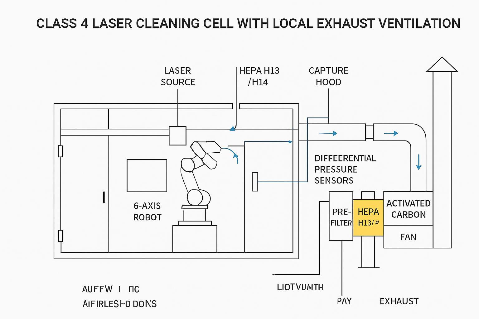
Ventilation and waste handling
Laser ablation generates particulates and, when removing coatings, volatile compounds. Local exhaust ventilation (LEV) should maintain negative pressure inside the cell and interlock airflow status with laser emission. A conservative, compliant path uses multi‑stage filtration with a final HEPA stage classified H13/H14 per EN 1822/ISO 29463 (overall efficiency ≥99.95%/≥99.995%), plus activated carbon for VOCs when coatings are involved. For an accessible explainer that references these HEPA classes, see Eaglewood Tech’s discussion of proper filtration of laser‑ablated particulates.
Ash and captured media must be handled per site hazardous waste procedures when coatings or metals warrant it; coordinate with EHS.
EU/US standards alignment
- IEC/EN 60825‑1 governs product classification and labeling; enclosures should ensure accessible emissions are Class 1 in normal use.
- ISO 11553‑1:2023 (Safety of machinery—Laser processing machines—Part 1) guides machine design and validation for laser processing equipment.
- Functional safety is derived from a risk assessment per ISO 12100 and implemented using EN ISO 13849‑1 for safety‑related parts of control systems; target PLr depends on hazards and is commonly PL d/e in robot cells.
- In the US, integrate ANSI Z136.1 with OSHA expectations (including LOTO where applicable); in the EU, pair ISO 11553‑1 with EN ISO 13849‑1 and EN 60204‑1 under the Machinery framework.
Automation and integration
Enclosures, robots, and interlocks
Aim for a Class 1 objective at the enclosure boundary. Typical architecture: interlocked doors, laser‑rated viewing windows, a safety PLC monitoring guard locks and E‑stops, validated stop categories, and airflow/ΔP signals tied to laser emission. Robot integration should be assessed through ISO 12100 and validated to the required PLr via EN ISO 13849‑1.
Functional safety and validation
Perform FAT/SAT that exercises every safety function: interlock fault detection, guard lock behavior, E‑stop timing, safe torque off, and extractor alarms inhibiting emission. Record evidence, version safety logic, and maintain change control. Validate airflow and pressure setpoints and verify window OD and labeling relative to wavelength and pulse characteristics.
Data, MES, and traceability
Traceability helps defend quality and accelerates troubleshooting. A practical minimal dataset aligned to ISA‑95/IEC 62264 includes: job/lot/serial ID; recipe ID/version; operator ID; timestamps; laser parameters (power, pulse width, frequency, scan speed, overlap, standoff); extractor differential pressure/alarms; verification results (visual grade, Ra/Rz, adhesion test where applicable). Exchange data with MES via OPC UA Machinery job models or MQTT—choose what your plant standardizes on.
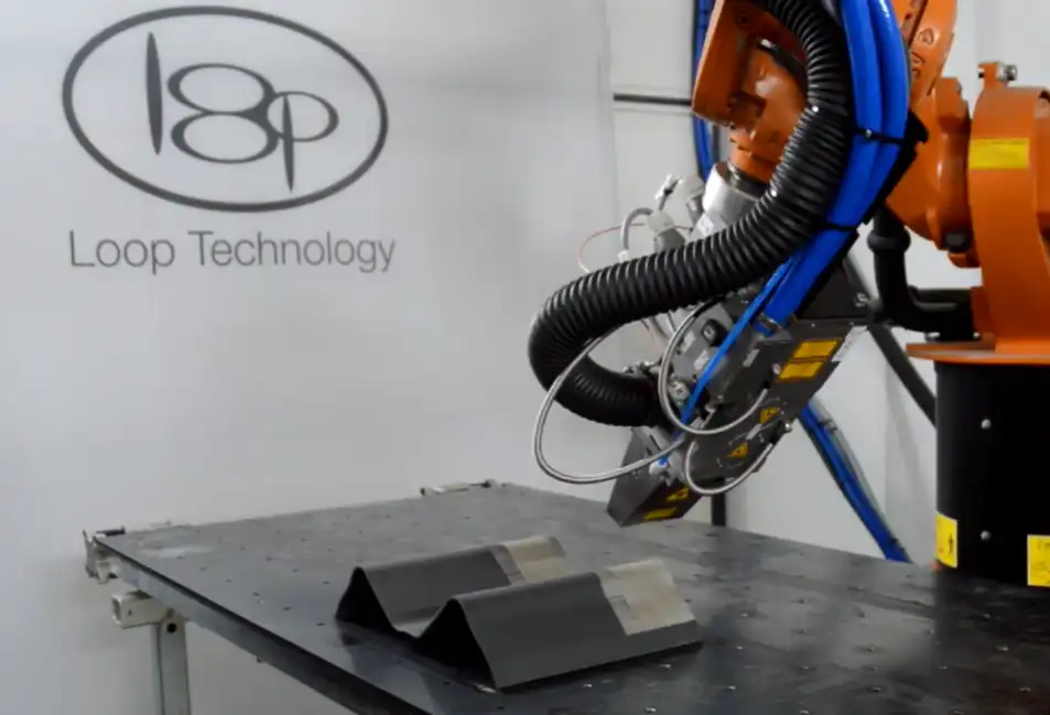
Disclosure: OceanPlayer is our product. In automated deployments, factory‑direct robotic laser cleaning cells with safety‑ready enclosures can be used to simplify integration and acceptance testing by unifying the laser, enclosure interlocks, and LEV monitoring under a single control and documentation set, which can then connect to MES via OPC UA or MQTT for traceability. Adapt this example to site requirements and internal standards.
ROI and selection: maximizing laser cleaning ROI
Cost elements and TCO model
Laser cleaning ROI depends on the whole system, not just the laser. A transparent TCO model should cover:
- CapEx amortization over 5–7 years (laser, enclosure, robot/PLC, LEV, installation).
- Energy consumption (laser electrical, chiller, extractor fans) at your utility rates.
- Maintenance: optics cleaning/replacement; filter media (prefilter cadence; HEPA/carbon per ΔP/TVOC); interlock and safety validation.
- Labor: operator loading/supervision; LSO program overhead.
- Consumables avoided: abrasives, solvents, PPE, and hazardous waste disposal.
- Quality and uptime gains: less rework/scrap; reduced cleaning time and changeovers.
To demonstrate laser cleaning ROI credibly, use site‑measured strip rates and yields from a pilot, not brochure values. Then run sensitivities on utilization (hours/year), strip rate (m²/hr), rework rate, filter life, and energy costs.
Pilot trials and throughput measurement
Run a DOE on representative parts. Log parameters for every run (power, pulse width, frequency, scan speed, overlap, standoff), measure area cleaned and time, and compute m²/hr with mean and standard deviation across at least 10 repetitions per condition. Verify surface outcomes: visual grade (e.g., ISO 8501‑1 or AMPP references where applicable), roughness per ASME B46.1/ISO 4287, and adhesion/crosshatch when relevant. Photograph before/after under consistent lighting and store results in your QMS alongside LEV readings (extractor ΔP, alarms) and safety checks.
A practical “go” threshold many teams use is capability at or above Cpk 1.33 for key metrics (throughput and surface quality). Adjust to your risk appetite and process criticality.
Sensitivity analysis and decision tree
- Sensitivity levers: utilization, strip rate, rework/scrap rate, filter life, energy tariff. Test best/expected/worst cases to see payback spread.
- Decision tree (simplified):
- Define the surface goal and takt time → if adhesion‑critical on thin parts, start with pulsed; if robust and area‑driven, evaluate CW.
- Run pilot DOE and verification → if quality fails at takt, adjust parameters or switch source modality.
- Validate safety/LEV and traceability → if compliance or data needs aren’t met, adapt enclosure and controls.
- Build TCO with pilot data → if payback within target window, move to procurement and detailed design.
Conclusion
Validate on representative parts with fully logged parameters and target surface standards before any CapEx decision. Then plan a staged deployment: factory acceptance testing (FAT), site acceptance testing (SAT), operator and maintainer training, and periodic audits—including safety re‑validation and LEV integrity checks—to sustain laser cleaning ROI over the life of the cell.
Selected citations (inline examples):
- For a practical overview and purchasing path to the ANSI safety standard, see ANSI Z136.1‑2022 (RLI product page).
- For an official overview of product safety classification and labeling scope, see IEC/EN 60825‑1 overview (SCC/CSA).
- For HEPA H13/H14 performance context in laser processes, see Eaglewood Tech’s explainer on filtration of laser‑ablated particulates.


