You need to consider several design specifications when you create a welded lap joint. You must choose the correct joint type and weld type. Overlap length and weld size have a big impact on strength. Material compatibility helps prevent weak spots. Strength requirements guide how much load the joint must hold. Welding codes and standards give you rules to follow for safe and reliable results.
Key Takeaways
- Pick the best joint and weld type for strength and saving money. Make sure the overlap is at least three times the thin plate’s thickness. Keep the gap small so the weld is strong and has no problems. Choose the right weld size for the sheet thickness to stop stress problems. Check the welds by looking, or using special tests, to make sure they are good.
Applicable standards & scope — read before applying
For design and acceptance criteria, refer to the relevant codes (for example, AWS D1.1 / D1.3 for structural and sheet‑steel work), drawing conventions (ISO 2553), weld quality levels (ISO 5817), and joint‑specific guidance such as ISO 14373 / IIW recommendations.
Typical applicability covers thin‑to‑medium gauge sheetwork (roughly 1–8 mm) and standard lap/butt joints; thicker sections or safety‑critical loads may need different rules. Always verify final criteria against local codes and a qualified engineer.
Lap Joint Types and Specifications
Single Lap Joint
A single lap joint is very common in welding. You make it by putting two metal pieces on top of each other. Then you weld along one side. This joint is easy and fast to make. People use it a lot for thin sheets and light things. The table below shows what a single lap joint is good for:
| Characteristic/Application | Description |
|---|---|
| Simplicity | Single lap joints are simple to get ready and use. |
| Suitability | Great for thin sheets, so you can use them in many ways. |
| Common Uses | Used a lot in sheet metal work, light building, and things that do not last long. |
| Limitation | Can bend or break if pulled because the load is not even. |
Single lap joints can do many jobs. But they might bend or break if you use too much force. The way the load sits can cause extra stress.
Double Lap Joint
A double lap joint has three layers of material. You put one piece in the middle and two on the outside. Then you weld both sides. This spreads the load better. It gives more strength and less chance of bending or peeling. Double lap joints are good for heavy loads. They help stop the joint from failing early because they balance the forces.
Fillet Weld Lap Joint
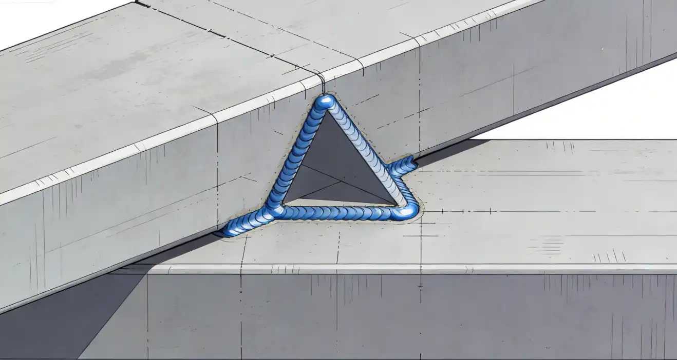
A fillet weld lap joint joins two plates that overlap. You make a triangle-shaped weld at the edge. You do not need to do much to the edges first. This type is easy to put together. It works even if the parts are not perfect. Fillet weld lap joints are used a lot because they are cheap and easy. But the overlap can waste some material.
Transverse and Longitudinal Welds
“Transverse fillet welds may behave differently from longitudinal welds under cyclic service; in many fatigue cases transverse details are more sensitive to crack initiation. The magnitude depends on material, thickness, loading direction, and weld quality—consult IIW/AWS fatigue classifications and industry guidance (see SSAB on fatigue) for detail.”
| Welding Direction | Fatigue Strength Comparison |
|---|---|
| Transverse | Stronger than longitudinal |
| Longitudinal | Weaker than transverse |
Picking the right joint and weld type changes how strong, cheap, and good your weld is. You should pick the joint type that fits your project best.
Lap Joint Design Parameters
Overlap Length Guidelines
You need to pay close attention to overlap length when you design a lap joint. Overlap length means how much one plate covers the other. A good rule is to make the overlap at least three times the thickness of the thinner sheet. This helps the joint carry more load and reduces the chance of failure. If you increase the overlap, you increase the load-carrying capacity. The table below shows how overlap length affects the joint:
| Overlap Length (mm) | Load-Carrying Capacity | Failure Mode Impact |
|---|---|---|
| 5 | Increased | Varies with material |
| 10 | Increased | Varies with material |
| 15 | Increased | Varies with material |
| 20 | Increased | Varies with material |
| 25 | Increased | Varies with material |
You should always check the material type and thickness before you decide on the overlap. A longer overlap makes the joint stronger and helps spread the force better.
For thin‑gauge work, verify your assumptions against the American Welding Society’s AWS D1.3/D1.3M:2018 Sheet Steel Code, which covers sheet steel up to 3/16 in (5 mm) with yield strengths ≤ 80 ksi and includes lap/fillet weld design and acceptance criteria (see Clause 1 scope and Clause 4 design).
Recommended Gap and Fit-Up
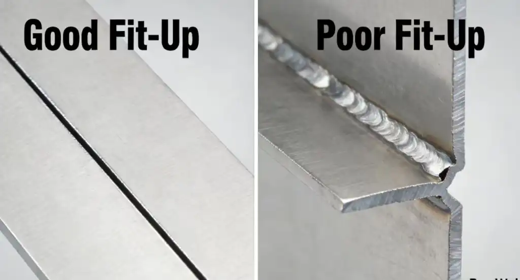
You must control the gap between the plates for a strong weld. A small gap helps the weld metal join both plates well. If the gap is too wide, the weld can become weak or have defects. Here are some important points for gap and fit-up:
- Keep gap tolerances under 0.5 mm for thin metal.
- Use a gap of 0.1-0.2 mm for materials under 1.5 mm thick.
- Tighter gaps prevent burn-through and give better weld penetration.
- Specify gap tolerances of 0.1-0.2 mm on your welding drawings.
- Machine the mating surfaces to ±0.05 mm for a good fit.
- Do not use general tolerances for weld-critical areas.
If you do not fit the plates well, you can get defects. The table below lists common problems from poor fit-up:
| Defect Type | Explanation |
|---|---|
| Lack of fusion | The weld metal does not fully bond with the base metal due to gaps or misalignment. |
| Incomplete penetration | Inadequate fit-up restricts the welding arc’s access to the joint root, leading to incomplete penetration. |
| Undercut | Excessive gaps can cause the base metal to melt away, resulting in a deeper weld groove. |
| Excessive reinforcement | Poor fit-up may lead to excessive weld metal deposition, causing stress concentration. |
| Misalignment | Results in angular or linear deviation, leading to uneven weld distribution and potential stress concentrations. |
Tip: Always check the fit-up before you start welding. Good fit-up means a stronger and more reliable joint.
Weld Size and Leg Dimensions
You need to choose the right weld size for a strong lap joint. The weld leg size should be equal to or just a bit smaller than the thickness of the sheet. If you make the weld too big or too small, you can cause problems. The weld size changes how stress spreads through the joint. A larger weld can create more stress in the heat-affected zone. The upper plate may bend down, and the lower plate may bend up. This can lead to weak spots or failure.
- Weld size affects the stress in the weld zone.
- Large welds can cause more stress in the heat-softened area.
- The plates can bend in different directions if the weld is not sized right.
You should always match the weld size to the sheet thickness for the best results.
Material Thickness Considerations
Material thickness is very important in lap joint design. The thickness of the plates changes how you weld and what type of weld you use. Thicker plates need more heat and a bigger weld. Thin plates need less heat and a smaller weld. If you use spot resistance welds, they work best for thin plates. You should not use them for heavy loads or thick materials.
- Material thickness affects the welding method and the strength of the joint.
- Sheet thickness changes the type of joint and how deep the weld goes.
- For spot welds, use them only for thin plates and thin-walled parts.
- Do not join more than three parts with a total thickness over 15 mm using resistance welds.
- The thickness ratio for each part should not be more than 1:3.
- Place spot welds so they only take shear force, not tension.
You should always check the thickness before you pick the weld type and size. This helps you make a strong and safe lap joint.
Welding Techniques and Best Practices
Joint Preparation
You must get your materials ready before welding a lap joint. Clean the surfaces to take off grease, oxides, and dirt. You can use mechanical, chemical, or laser cleaning methods. These ways help make sure the metal is clean. Straight and flat edges help stop weld defects. Follow these steps for good results: Prepare the edges of your material first. Tack the pieces together and put the wire electrode in the right spot. Run beads along the outer edges. Work toward the middle at a 45-degree angle.
Tip: Clean surfaces and careful edge preparation help you make strong welds without defects.
Case example (reproducible WPS/PQR summary):
- Application: 2.5 mm 5xxx-series aluminum, flat position lap joint, fillet weld, robot‑assisted GMAW (MIG).
- WPS fragment: ER5356 wire 1.2 mm, polarity DC+; current 150–180 A; voltage 16–18 V; travel speed 250–350 mm/min; shielding gas 100% Ar; contact tip-to-work 10–12 mm.
- PQR key points: qualified by visual, bend (2T), and macro etch showing full fusion; tensile > specified base metal; acceptance: no porosity >1 mm, no lack of fusion.
- Fit-up note: maintain gap ≤0.2 mm and overlap ≥3× thinner plate thickness to control penetration and avoid burn‑through.
Process Selection (MIG, TIG, Stick)
You need to pick the right welding process for your project. The type and thickness of your base material matter. Welding position and project needs also change your choice. Use the table below to compare common welding processes:
| Factor | Description |
|---|---|
| Base Material Type and Thickness | Thicker materials need deeper penetration. Thin sections need narrow patterns to stop burn-through. |
| Welding Position | Flat, horizontal, vertical, or overhead positions change how the weld pool moves. |
| Welding Process | MIG is easy for beginners. TIG makes neat welds. Stick works well for tricky patterns. |
| Project Requirements | Some jobs need strength. Others need a nice look. |
Welding Settings
You must set your welding parameters with care. Change current, voltage, electrode angle, and travel speed for the best weld. The table below shows how each setting affects your weld:
| Welding Current | Increased current raises penetration and heat input—improving fusion potential but also increasing risk of undercut, distortion and porosity; set current in balance with voltage, travel speed and wire‑feed and verify settings through process trials. |
Slow travel speed can make wide beads and poor penetration. High wire feed or amperage can cause spatter. Low amperage makes narrow beads with weak tie-in.
Note: Use the right settings for your material. This helps you avoid distortion and get deep welds.
Inspection and Quality Control
You need to check your welds to find defects. Use visual testing for a quick look. Penetrant testing helps you find surface flaws. Ultrasonic testing finds hidden problems and checks thickness. The table below compares inspection methods:
| Method | Advantages | Limitations |
|---|---|---|
| Penetrant Testing | Finds surface flaws; easy to see | Misses hidden defects; needs cleaning |
| Ultrasonic Testing | Finds hidden flaws; checks thickness | Needs skilled workers; costs more |
| Visual Testing | Simple; good for first check | Misses hidden defects; depends on the person |
Quality control helps you stop mistakes like incomplete fusion, porosity, cracking, and distortion. Keep records of your welding settings and inspection results. This helps you make strong lap joints for important structures.
You must follow clear rules when making welded lap joints. The table below explains what helps these joints stay strong and work well:
| Characteristic | Description |
|---|---|
| Overlapping metal pieces | Two pieces cover each other to add strength. |
| Ease of welding | This joint is simple to weld and check. |
| Thickness compatibility | It works with many thicknesses, so it is flexible. |
You get better lap joints if you use good steps:
- Checking the joints often helps you spot problems soon.
- Skilled welders make sure the joints are high quality.
- Using codes helps stop failures and keeps joints safe.
To make lap joints strong and safe, always use the right steps and check your work. If you want more help, ask welding experts.
FAQ
What is the minimum overlap for a welded lap joint?
You should use an overlap at least three times the thickness of the thinner plate. This helps the joint stay strong and prevents early failure.
What weld type works best for lap joints?
You can use fillet welds for most lap joints. They are easy to make and work well for many materials and thicknesses.
What problems can poor fit-up cause in lap joints?
Poor fit-up can cause defects like lack of fusion, incomplete penetration, or misalignment. These problems make the joint weak and unsafe.
What inspection methods check welded lap joints?
You can use visual testing, penetrant testing, or ultrasonic testing. Each method helps you find different types of defects in the weld.
References and further reading
- SMACNA (2024), “MIG & TIG vs. Laser Welding” — overview of material thickness suitability and when laser welding is competitive with arc methods: SMACNA — MIG & TIG vs. Laser Welding (2024).
- IPG Photonics (2024), “Real‑Time Weld Measurement” — technical notes on inline coherent imaging (ICI/OCT) for keyhole depth monitoring and process control used to raise first‑pass yield: IPG Photonics — Real‑Time Weld Measurement (2024).
- IPG Photonics (2024), LightWELD FAQ — directional performance notes (laser vs. TIG) and practical application guidance for automated welding solutions: IPG LightWELD FAQ (2024).
- IPG Photonics (2024), Investor Presentation — market trends and productivity framing that contextualize automation and laser adoption (labor shortage, efficiency): IPG Photonics — Investor Presentation (2024).
- Coherent, “Laser Safety Standards” overview — concise summary of ISO 11553 and global laser safety references suitable for cell design and compliance planning: Coherent — Laser Safety Standards.
- Lawrence Berkeley National Laboratory EHS (2024), Laser Safety chapter — practical guidance on appointing a Laser Safety Officer (LSO) and establishing controlled areas under ANSI Z136.1 principles: LBL EHS — Laser Safety (2024).
- Peer‑reviewed analysis of keyhole stabilization and monitoring (2024) — technical background on keyhole behavior relevant to parameter selection and inline monitoring: Keyhole stabilization and dynamics (2024) — PMC article.
- Practical comparison and buyer guidance (industry posts, use sparingly for directional context):
- Cobot.systems, “Laser Vs. TIG Welding” (2024): Cobot.systems — Laser vs TIG (2024).
- MimoWork, “Laser Welder Machine: Better Than TIG & MIG” (2024): MimoWork — Laser Welder Machine (2024).
- Fox Valley Stamping, “Laser Welding vs MIG vs TIG” (overview guide): Fox Valley — Laser vs MIG vs TIG.
- Example industrial adoption (2025 ESG / application context): DMEGC Solar — ESG report noting use of laser welding in PV assembly lines: DMEGC Solar — 2025 ESG report.


