The gate is the single most consequential design decision in any injection mold — get it wrong, and you’re chasing jetting, flow marks, and warpage for the life of the tool. This guide breaks down every major gate type, explains when each one makes sense, and walks through the gate location strategies that prevent the defects most molders struggle with. Whether you’re specifying a new tool or troubleshooting an existing one, the frameworks here will sharpen your decision-making.
What Does the Gate Do in Injection Molding
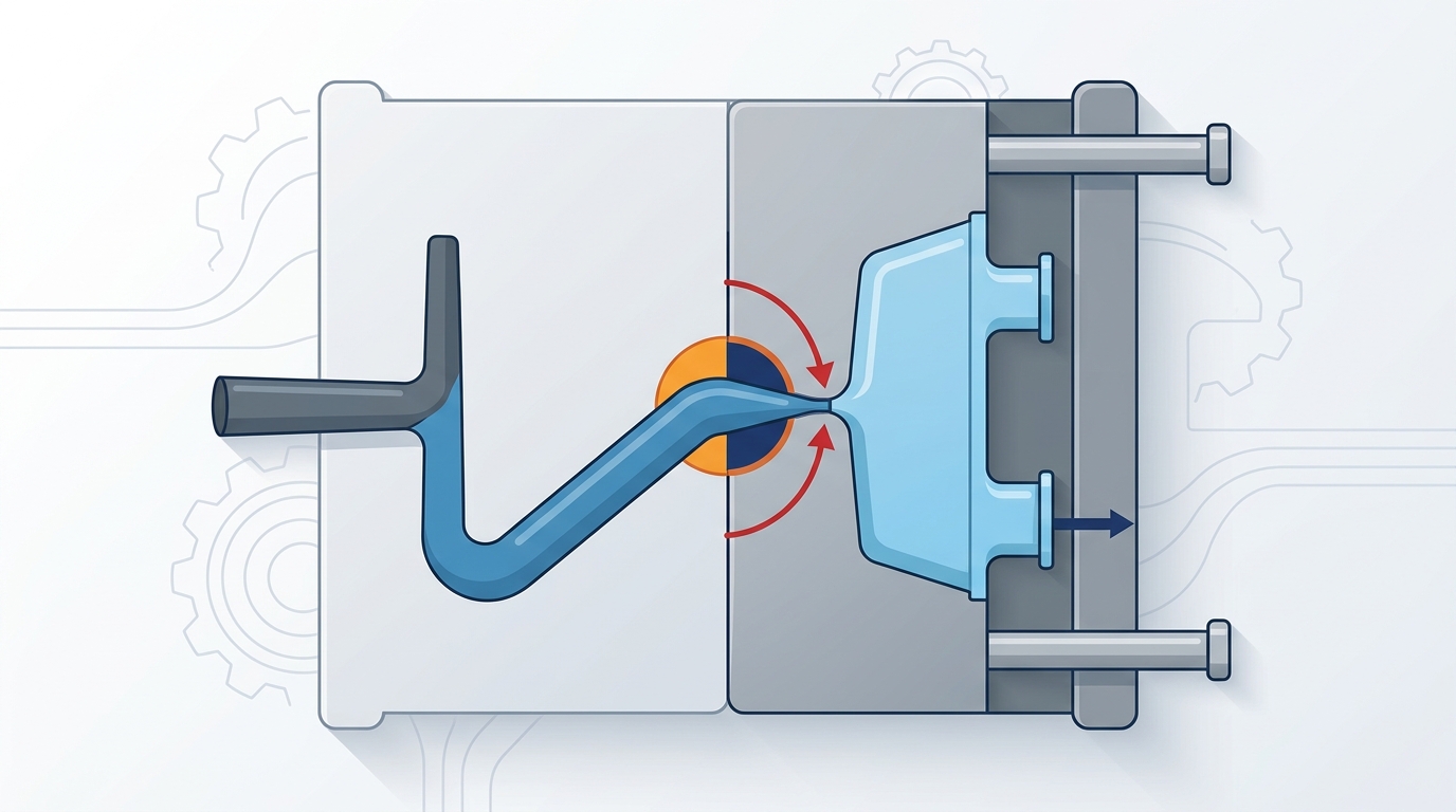
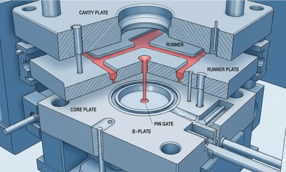
Think of the gate as a valve between the runner system and the part cavity. It controls three things simultaneously: melt flow velocity, injection and packing pressure, and backflow prevention once the screw begins to decompress. Every other aspect of mold performance — fill balance, cosmetic quality, dimensional stability — traces back to how well the gate executes these three functions.
During the filling phase, the gate’s cross-sectional area dictates how fast molten resin enters the cavity. A gate that’s too small creates excessive shear heating and pressure drop. Too large, and you lose the ability to control packing independently of fill, which almost always leads to over-packing near the gate and sink marks far from it.
The packing and holding phase is where gate design really earns its keep. The gate must stay open (molten) long enough to transmit holding pressure into the cavity, compensating for volumetric shrinkage as the part cools. This window is called gate freeze-off time, and it’s one of the most under-discussed variables in mold design. Freeze off too early, and you get sink marks and voids. Freeze off too late, and cycle time balloons.
After packing, the solidified gate acts as a physical seal that prevents molten material from flowing back into the runner. This backflow prevention is critical — without it, you’d see inconsistent part weights shot to shot, and dimensional control would be nearly impossible.

Injection mold gate function diagram showing melt flow control during filling and packing phases
Key Factors That Influence Gate Design Selection
Choosing a gate type isn’t a cookbook exercise. It requires balancing at least six variables, and they often conflict with each other.
Part geometry is the starting point. A deep-draw cylindrical part suggests a different gate strategy than a flat panel. Wall thickness uniformity matters enormously — parts with significant thickness transitions need gates positioned to fill thick sections first, allowing thin sections to pack through the thicker regions.
Resin type changes everything. High-viscosity materials like polycarbonate or glass-filled nylon demand larger gate cross-sections to keep shear rates within safe limits. Shear-sensitive resins like PVC or POM can degrade at the gate if the shear rate exceeds roughly 40,000–60,000 s⁻¹, depending on the specific grade. This is a hard constraint, not a guideline.
A factor that many designers overlook: the cold slug well. When the machine nozzle sits against the sprue bushing between shots, a small plug of cooled material forms at the tip. Without a properly sized cold slug well opposite the gate, that cold slug gets injected directly into the cavity, causing surface blemishes and weak weld lines. The well should be at least 1.5 times the runner diameter in depth.
Cosmetic requirements often override engineering logic. If the gate vestige can’t be visible, you’re immediately ruling out direct gates and most edge gate positions on A-surfaces. This single constraint pushes many projects toward sub gates or valve gates, even when a simple edge gate would be more process-friendly.
Production volume drives the economic calculation. A 50,000-piece run doesn’t justify the cost of a hot runner system, but a 5-million-piece program almost certainly does. The gate type you select cascades into decisions about runner layout, mold complexity, and cycle time — all of which hit the per-part cost.
And then there’s the runner system itself. Cold runner molds pair naturally with edge gates, sub gates, and pin gates. Hot runner systems open up options like valve gates and thermal gates that simply aren’t possible with cold runners. The gate and runner system must be designed as a unit, not independently.
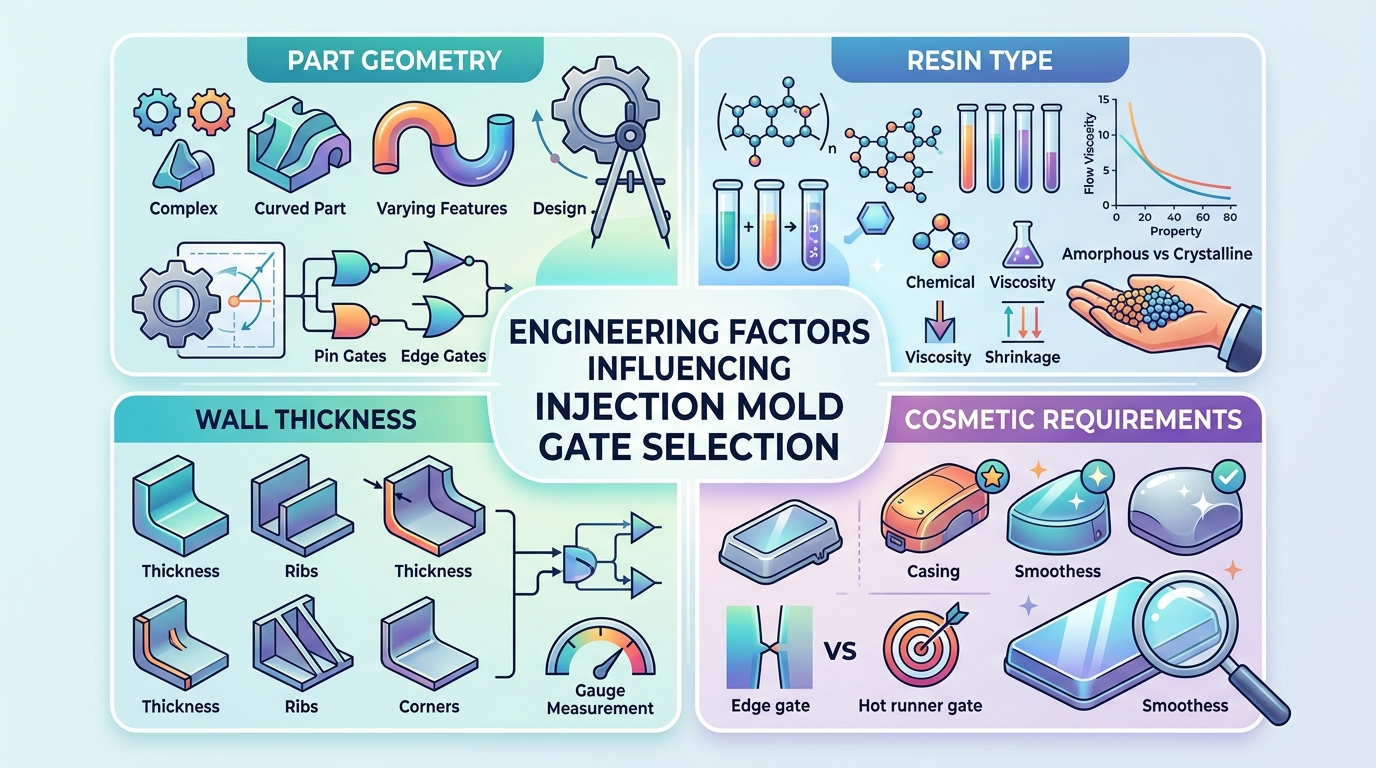
Key engineering factors for injection mold gate design selection including geometry, resin, wall thickness, and cosmetics
Edge Gate — Structure, Advantages, and Best Applications
The edge gate is the workhorse of injection molding. If you’ve designed or run molds for any length of time, you’ve worked with hundreds of them. It’s the default for good reason — simple to machine, easy to modify, and forgiving across a wide process window.
Structurally, the edge gate sits at the parting line and feeds material into the cavity through a rectangular cross-section. Typical dimensions range from 0.5–1.5 mm in thickness (the short dimension) and 1.5–12 mm in width, depending on part size and resin. The width-to-thickness ratio usually falls between 2:1 and 6:1. This rectangular profile gives you independent control over two critical variables: the width governs volumetric flow rate, while the thickness controls gate freeze-off time and shear rate.
One of the edge gate’s biggest practical advantages? Ease of modification on the bench. If the gate is too restrictive during initial sampling, a toolmaker can weld and re-cut it in a few hours. Try doing that with a sub gate buried inside the mold — it’s a completely different level of effort.
Edge gates work best for:
- Flat or box-shaped parts where the gate can feed along the longest flow path
- Medium-to-thick wall sections (1.5 mm and above)
- Parts where the parting line edge is non-cosmetic or will be trimmed
- Prototype and low-volume molds where simplicity reduces tooling cost
The limitations are real, though. Edge gates leave a visible vestige at the parting line that typically requires manual trimming or secondary degating — a labor cost that adds up fast at high volumes. And because the gate is at the parting line, it can only feed from the part’s perimeter, which limits your options for center-gated fill patterns on round or symmetrical parts.
A common mistake: making the edge gate too thin in an attempt to minimize vestige. This spikes shear rate, which can cause material degradation right at the gate entrance — you’ll see it as brown streaks or a hazy region near the gate on clear parts. Keep the gate thickness above 50–80% of the nominal wall as a starting rule, then refine with flow simulation.
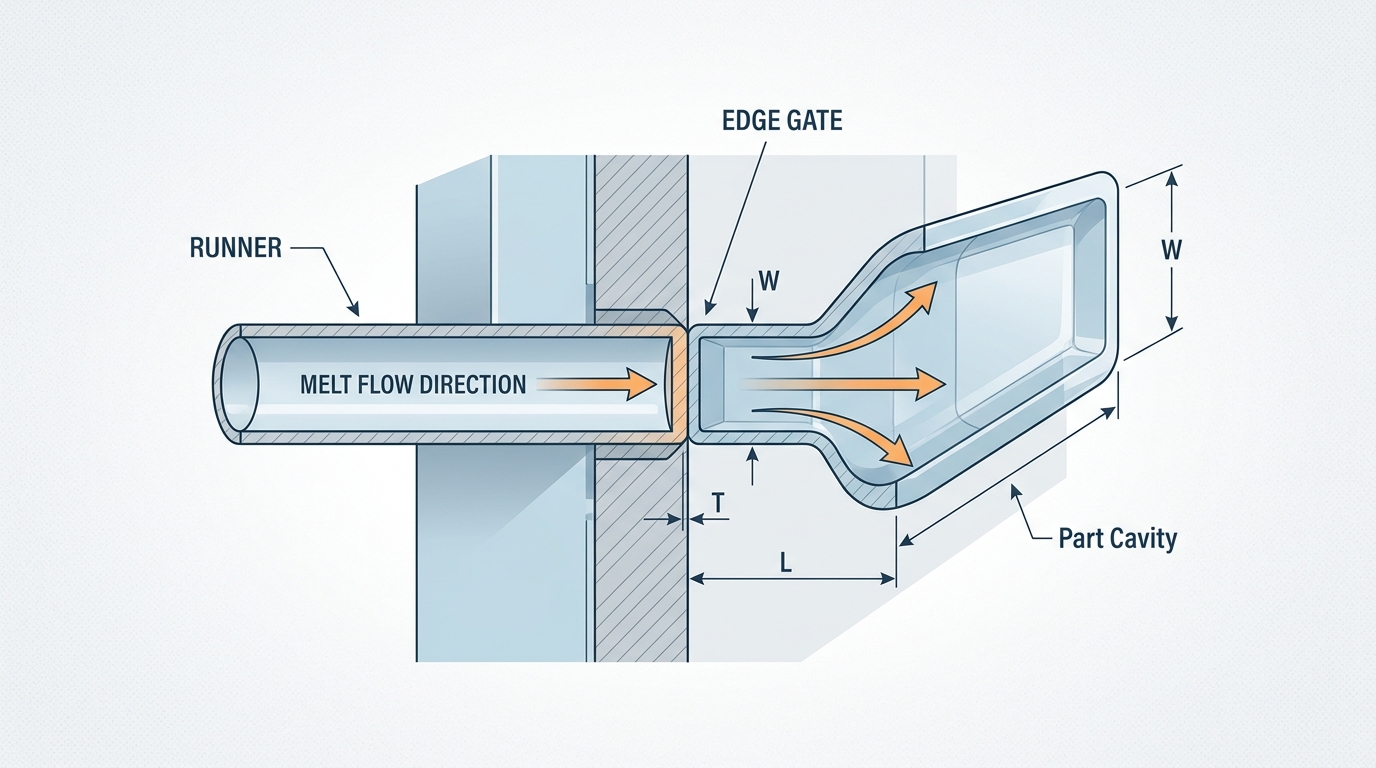
Edge gate cross-section diagram showing rectangular geometry, dimensions, and melt flow direction
Sub Gate — Automatic Degating for High-Volume Production
The sub gate — also called a submarine gate or tunnel gate — solves the biggest drawback of the edge gate: manual trimming. By angling the gate channel below the parting line surface, the gate shears off automatically during ejection. For high-volume production, this single feature can justify the added mold complexity.
The geometry is straightforward in concept but demanding in execution. A conical or tapered tunnel is machined at an angle (typically 30°–45° to the parting line) from the runner into the cavity. As the mold opens and ejector pins push the part forward, the gate stretches and snaps at its thinnest point. The runner and gate remnant stay on the opposite mold half or fall free.
There are several sub gate variants worth knowing:
Standard conical sub gate: The most common. Works well for semi-crystalline materials like PP, PE, and nylon that have enough elongation to stretch and break cleanly. Gate diameter at the part surface typically ranges from 0.8–2.0 mm.
Banana sub gate (curved tunnel): The tunnel curves so the gate enters the part on the opposite side from the runner. This allows gating on the underside of a part — extremely useful when the top surface is cosmetic and the parting line location doesn’t allow a standard sub gate.
Cashew gate: A more aggressively curved variant of the banana gate, shaped like a cashew nut. It can reach gating locations that would be impossible with a straight tunnel. The trade-off is that the curved steel core is fragile and prone to breakage, especially in hardened tool steels. Expect to carry spare inserts.
Sub gates do have a critical limitation: they don’t work well with brittle or low-elongation materials. Amorphous resins like polystyrene or SAN can shatter rather than shear cleanly, leaving gate fragments attached to the part or — worse — stuck in the tunnel. Glass-filled materials above 20–30% loading can also be problematic because the glass fibers reduce ductility at the gate.
The tunnel geometry demands tight tolerances. If the tunnel angle is too steep, the gate won’t shear cleanly. Too shallow, and it won’t release from the runner. Surface finish inside the tunnel matters too — any roughness creates drag that can prevent clean ejection. Polish the tunnel to SPI A-2 or better.
Sub gate tunnel geometry diagram showing angled tunnel design and automatic degating mechanism during mold ejection
Pin Gate — Precision Gating for Three-Plate Molds
The pin gate is a small-diameter circular gate — typically 0.8–1.5 mm — that feeds the part from a runner plate above (or below) the cavity. It requires a three-plate mold construction, where the runner system sits on a separate plate from the cavities and the core. When the mold opens, it opens in two stages: first separating the runner plate to break the pin gates, then opening the main parting line to eject parts.
Why go through this added complexity? Two reasons stand out.
First, pin gates allow center gating on round or cylindrical parts. An edge gate on a round part creates asymmetric flow, which almost guarantees warpage. A pin gate at the geometric center produces radial flow — uniform fill, uniform shrinkage, minimal warpage. For parts like gears, caps, and round housings, this is often the only gate type that produces acceptable results.
Second, pin gates enable multi-cavity layouts with balanced filling. Because the runner system is on a separate plate, you can route runners to the optimal gate location on each cavity without being constrained by the parting line geometry. A 16-cavity mold with pin gates at the center of each cavity will fill more uniformly than the same mold with edge gates.
The trade-offs are significant. The small gate diameter means high shear rates and substantial pressure drop at the gate restriction. For high-viscosity resins, this can push injection pressure requirements beyond the machine’s capability. You need to run the numbers — calculate the shear rate at the gate using the standard formula (γ = 4Q/πr³ for a circular gate) and verify it stays within the resin manufacturer’s recommended limits.
Gate freeze-off happens fast with pin gates due to the small diameter. This limits packing time, which can be a problem for thick-walled parts that need extended holding pressure to prevent sink marks. If your part has wall sections above 3 mm, a pin gate may freeze off before the core of those thick sections has solidified enough.
The vestige left by a pin gate is small — just a tiny raised dot — which makes it acceptable on many semi-cosmetic surfaces. But “small” isn’t “invisible.” On high-gloss or optically critical parts, even a pin gate vestige may need secondary finishing.
Direct Gate and Other Specialized Gate Types
The direct gate — sometimes called a sprue gate — is the simplest possible configuration. The machine nozzle feeds directly into a sprue bushing, and the sprue connects straight into the part cavity with no runner system at all. One cavity, one gate, zero runner waste.
This sounds ideal until you consider the downsides. The gate vestige is large (the full sprue diameter, typically 4–8 mm), and it requires machining or grinding to remove. The large gate also means extended gate freeze-off time, which inflates cycle time. Direct gates are best reserved for large single-cavity parts where the sprue can enter a non-cosmetic surface — think bucket bottoms, large container bases, or structural components that will be hidden in assembly.
Beyond the four core types (edge, sub, pin, direct), several specialized gates solve specific problems:
Valve gate: A hot runner gate with a mechanical pin that opens and closes the gate orifice. The pin retracts during injection and advances to seal the gate before the part cools. The result is a nearly flat, vestige-free gate surface — the gold standard for cosmetic parts. Valve gates add significant cost to the hot runner system (each gate needs its own actuator), but for automotive interior panels, consumer electronics housings, and medical device covers, the surface quality justifies the investment.
Fan gate: A wide, fan-shaped gate that spreads the melt across a broad front as it enters the cavity. Fan gates are designed for wide, flat parts where uniform flow front advancement is critical — optical lenses, light guide plates, and large flat panels. The wide entry reduces shear and produces a more laminar flow front, minimizing flow marks and orientation effects.
Film gate (flash gate): Essentially a fan gate taken to its extreme — the gate extends across the entire width of the part. Film gates are used for very thin, wide parts where any flow imbalance would cause warpage. The entire gate must be trimmed after molding, which adds post-processing cost but delivers unmatched fill uniformity.
Diaphragm gate: A 360° gate used for tubular parts, where the melt enters around the entire circumference simultaneously. Eliminates weld lines entirely on cylindrical parts — critical for parts that need burst pressure resistance or uniform mechanical properties around the circumference.
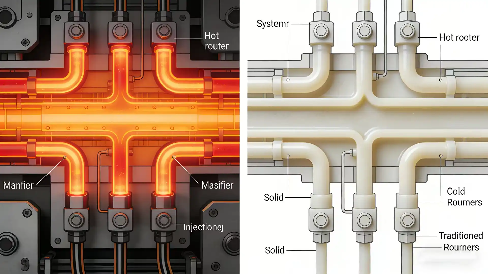
Hot Runner vs Cold Runner Gating Systems
This decision shapes everything downstream — part cost, cycle time, gate vestige quality, and how much flexibility you have in gate placement. Most people frame it as a cost question, but it’s really a system design question.
Cold runner systems are the traditional approach. The runner solidifies with each shot and must be ejected along with the parts. For materials that can be reground (most commodity resins), the runner gets granulated and blended back into virgin material. For engineering resins where regrind isn’t acceptable — medical-grade materials, optical-grade PC, certain flame-retardant compounds — every gram of runner is pure waste.
| Factor | Cold Runner | Hot Runner |
|---|---|---|
| Material waste | 5–40% of shot weight (runner scrap) | Near zero |
| Cycle time | Longer (runner must cool) | Shorter (no runner cooling needed) |
| Gate vestige | Varies by gate type; often needs trimming | Minimal with valve gates; small with thermal gates |
| Tooling cost | Lower ($5K–$30K less depending on cavitation) | Higher (manifold + drops + controllers) |
| Maintenance complexity | Simple — no heaters, thermocouples, or controllers | Significant — heater failures, tip wear, color changes |
| Color change time | Fast (just purge the barrel) | Slow (must purge entire manifold) |
| Gate location flexibility | Limited to parting line or sub-gate angles | Almost unlimited — can gate anywhere on the part |
The break-even calculation depends heavily on resin cost and annual volume. As a rough benchmark: if your annual resin spend on runner waste exceeds the amortized hot runner cost over the tool’s lifetime, hot runner wins economically. For expensive engineering resins (PEEK, LCP, medical-grade materials), that break-even can come at surprisingly low volumes — sometimes under 100,000 parts per year.
There’s a hybrid approach worth considering: hot-to-cold systems. A hot runner manifold feeds a short cold runner section, which then gates into the cavities via conventional edge or sub gates. You get the material savings of a hot runner with the simpler gate geometry and easier maintenance of cold runner gates. This is particularly common in multi-cavity family molds where different parts need different gate sizes.
One thing that rarely gets mentioned in hot runner discussions: residence time. The resin sits in the hot runner manifold at processing temperature between shots. For heat-sensitive materials, extended residence time causes thermal degradation — you’ll see it as black specks, discoloration, or reduced mechanical properties. If your cycle time is long or you’re running a low-cavitation mold with a large manifold, calculate the residence time and compare it to the resin’s thermal stability window.
Gate Location Optimization to Reduce Defects and Pressure Drop
You can select the perfect gate type and still get terrible results if you put it in the wrong place. Gate location is where mold design shifts from mechanical engineering to something closer to fluid dynamics art.
The fundamental rule: gate into the thickest section. Plastic flows from thick to thin much more easily than thin to thick. When melt enters a thin section first and then tries to fill a thicker section behind it, the thin section freezes off while the thick section is still packing. The result is sink marks in the thick areas and over-packing stress in the thin areas. Gating into the thickest wall allows the melt to flow outward through progressively thinner sections, maintaining packing pressure throughout the fill.
Weld lines form wherever two flow fronts meet. You can’t always eliminate them, but you can relocate them by adjusting gate position. The goal is to push weld lines into structurally non-critical areas and away from cosmetic surfaces. In a part with holes or core pins, each obstruction splits the flow and creates weld lines on the downstream side. Moving the gate changes the flow pattern and shifts where those weld lines form.
Air traps occur where converging flow fronts trap air that can’t escape through vents. Gate location directly determines the filling pattern, which determines where air gets pushed. The ideal scenario: the flow front advances uniformly toward the parting line edges where vents are located, sweeping air ahead of it. A poorly placed gate can create pockets where air gets surrounded by melt with no escape path — the result is a burn mark or a short shot in that area.
Pressure drop management is the quantitative side of gate location optimization. Every millimeter of flow path adds pressure drop. If the gate is at one end of a long part, the far end sees significantly less packing pressure than the near end. This pressure gradient creates differential shrinkage, which manifests as warpage. For long parts, consider gating at the center to cut the maximum flow length in half — this roughly halves the pressure drop to the furthest point.
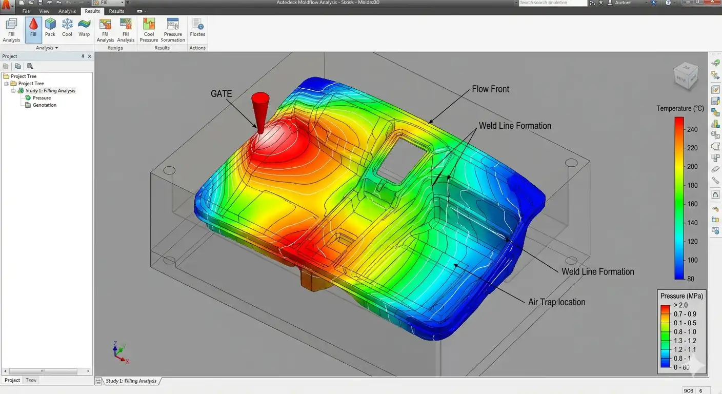
Modern mold flow simulation software — tools like Autodesk Moldflow — can predict fill patterns, weld line locations, air trap positions, and pressure distributions for any gate location you specify. Running a fill analysis before cutting steel isn’t optional anymore. It’s malpractice not to. A single simulation iteration costs a few hundred dollars; a gate relocation on a hardened mold costs tens of thousands.
One nuance that simulation sometimes misses: gate blush and cosmetic impact zones. The area immediately around the gate experiences the highest shear and temperature, which can create a visible halo or texture difference on the part surface. Even if the simulation shows perfect fill, you need to consider whether the gate’s cosmetic impact zone overlaps with a visible surface. This is especially critical for textured parts — the gate blush area often takes texture differently than the rest of the surface.
Preventing Molding Defects Caused by Poor Gate Design
Most molding defects trace back to one of two root causes: the gate is the wrong size, or it’s in the wrong place. Here’s how to diagnose and fix the most common gate-related problems.
Jetting
Jetting happens when the melt stream shoots through the gate like a jet and snakes across the cavity floor before the cavity fills volumetrically. You’ll see it as a wormy, folded pattern on the part surface near the gate. The root cause is almost always a gate that’s too small relative to the cavity thickness, combined with a gate that aims into open space rather than against a cavity wall.
The fix: redirect the gate so the melt impinges on a wall immediately upon entry. This breaks up the jet and forces the melt to spread as a fountain flow front. Alternatively, enlarge the gate to reduce the melt velocity at entry. Slowing down the injection speed during the initial fill phase can also help, but that’s a process band-aid — the design fix is more reliable.
Flow Marks
Flow marks appear as wavy lines or surface ripples, usually starting near the gate and extending along the flow path. They’re caused by the melt front alternately freezing and re-melting against the cavity wall as it advances. Gate-related causes include insufficient gate size (which creates a hesitation effect as the melt squeezes through) and gate locations that create long, thin flow paths.
Increasing gate size, raising mold temperature, and increasing injection speed all help — but the most permanent fix is ensuring the gate feeds into a section thick enough that the flow front doesn’t hesitate.
Black Specks and Material Degradation
When you see black specks concentrated near the gate, the material is degrading due to excessive shear heating at the gate restriction. This is common with heat-sensitive resins (PVC, POM, certain TPEs) pushed through undersized gates at high injection speeds.
Calculate the shear rate at the gate. If it exceeds the resin supplier’s maximum recommended value, the gate must be enlarged. There’s no process adjustment that safely compensates for a gate that’s thermally destroying the material. The Plastics Today technical library has useful reference data on shear rate limits for common resins.
Short Shots
If the part consistently fills 90–95% but won’t complete, and you’ve ruled out venting issues, the gate may be freezing off before the cavity is full. This happens when the gate cross-section is too small — it solidifies before the fill phase completes. The solution is straightforward: increase gate thickness to extend freeze-off time beyond the fill time.
Sink Marks Near and Far from the Gate
Sink marks near the gate usually indicate the gate is too large — it stays open so long that packing pressure causes over-packing near the gate while far regions still shrink. Sink marks far from the gate indicate the opposite: the gate freezes off too early, cutting off packing pressure before distant thick sections have solidified.
This is a balancing act. Gate freeze-off time needs to match the cooling time of the thickest section along the flow path. Flow simulation is the most reliable way to optimize this relationship — as recommended by the Society of Plastics Engineers in their mold design best practices.
Frequently Asked Questions About Injection Mold Gate Design
How do you determine the correct gate size?
Start with the gate thickness at 50–80% of the part wall thickness. For the width (on rectangular gates), use 1.5–3x the thickness. Then verify with flow simulation — calculate the shear rate at the proposed gate dimensions using the volumetric flow rate from your target fill time. If shear rate exceeds the resin’s limit, increase the gate size. If gate freeze-off time is shorter than required packing time, increase thickness. These are iterative calculations, not one-shot formulas.
When should you use multiple gates on a single part?
Multiple gates make sense when a single gate can’t fill the part within acceptable pressure limits, or when the flow length from one gate creates unacceptable pressure gradients and warpage. Large parts, long parts, and parts with isolated sections (like a frame with a center opening) often need two or more gates. The trade-off: every additional gate creates at least one additional weld line. Position those weld lines deliberately, not accidentally.
How does gate design affect cycle time?
Gate freeze-off time sets the minimum packing/holding time. A thicker gate takes longer to freeze, extending cycle time. A thinner gate freezes faster but may not allow enough packing. The optimal gate delivers just enough freeze-off time to adequately pack the part — and not a second more. On a 20-second cycle, shaving 2 seconds off gate freeze-off time by optimizing gate thickness can improve throughput by 10%.
What is gate freeze-off time and why does it matter for packing?
Gate freeze-off is the moment the gate solidifies completely, sealing the cavity from the runner. After freeze-off, no additional material can enter the cavity, so any shrinkage that occurs after this point creates voids or sink marks. The gate must remain open long enough to compensate for roughly 90–95% of the total volumetric shrinkage. Simulation software can predict freeze-off time based on gate geometry, melt temperature, and mold temperature.
How do you minimize gate vestige on cosmetic parts?
Valve gates produce the cleanest vestige — nearly flush with the part surface. If a valve gate isn’t in the budget, sub gates placed on non-visible surfaces are the next best option. For edge gates, careful sizing and sharp gate land geometry produce a cleaner break. Post-molding, vestige can be trimmed, milled, or laser-finished, but every secondary operation adds cost. The best strategy is designing the vestige out from the start.
Can you change the gate type after the mold is built?
Sometimes, but it’s expensive. Converting an edge gate to a sub gate requires re-machining the cavity insert and potentially redesigning the ejection system. Switching from cold runner to hot runner is essentially a mold rebuild. Minor modifications — widening an edge gate, adjusting a sub gate angle — are feasible. Major gate type changes should be avoided by investing in proper simulation and design review before steel is cut.
Choosing the Right Gate Type — A Practical Decision Framework
After 3,000 words of detail, here’s the distilled decision logic. Ask these questions in order, and the answers will narrow your gate type selection to one or two options.
Question 1: Does the gate vestige need to be invisible?
Yes → Valve gate (hot runner) or sub gate on hidden surface.
No → All options remain open.
Question 2: Is automatic degating required for production volume?
Yes → Sub gate or hot runner (valve or thermal gate).
No → Edge gate and pin gate remain viable.
Question 3: Does the part need center gating for uniform fill?
Yes → Pin gate (three-plate mold) or hot runner drop at center.
No → Edge gate is likely the simplest solution.
Question 4: Is the resin brittle or glass-filled above 20%?
Yes → Avoid sub gates (risk of incomplete shearing). Use edge gate or hot runner.
No → Sub gates are viable.
Question 5: Does the production volume justify hot runner investment?
Yes → Hot runner with valve or thermal gates.
No → Cold runner with edge, sub, or pin gate.
| Gate Type | Best For | Avoid When | Vestige Quality | Automation |
|---|---|---|---|---|
| Edge Gate | Flat/box parts, prototyping, easy modification | Cosmetic surfaces at parting line | Moderate — requires trimming | Manual degating |
| Sub Gate | High-volume production, hidden gate location | Brittle resins, high glass-fill content | Good — small vestige below parting line | Automatic degating |
| Pin Gate | Round parts, multi-cavity center gating | Thick walls needing long packing, high-viscosity resins | Good — small circular mark | Automatic (three-plate separation) |
| Direct Gate | Large single-cavity parts, maximum packing | Cosmetic parts, multi-cavity molds | Poor — large sprue vestige | Manual removal |
| Valve Gate | Cosmetic-critical surfaces, hot runner systems | Low-budget tooling, simple parts | Excellent — nearly flush | Fully automatic |
| Fan/Film Gate | Wide flat parts, optical components | Small parts, cost-sensitive projects | Poor — full-width trimming needed | Manual trimming |
One final point that deserves emphasis: no gate design decision should be finalized without mold flow analysis. The variables interact in ways that intuition alone can’t predict. A simulation run costs a fraction of a mold modification, and it catches problems — pressure drop issues, weld line positions, air traps, unbalanced filling — before they become steel-cutting mistakes. Treat simulation as a required engineering step, not an optional luxury.
Gate design is where mold engineering meets process engineering. The best gate is the one that fills the part uniformly, packs it adequately, freezes off at the right moment, leaves an acceptable vestige, and does all of this reliably over hundreds of thousands of cycles. Use the framework above to narrow your options, validate with simulation, and you’ll avoid the costly trial-and-error that plagues too many mold launches.


