Introduction
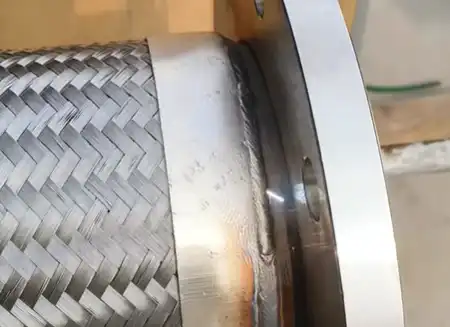
Configured correctly, selective laser cleaning removes rust, oxides, oils, and paint while preserving the underlying metal. The physics hinge on absorption contrast and ablation thresholds: contaminants typically absorb more energy and release at lower thresholds than the base material, enabling precise removal without cutting into the substrate or shifting its microstructure. That’s why many teams evaluate laser cleaning for weld prep surfaces and for paint/coating strip tasks.
In this guide, you’ll learn how selective removal works, how to set parameters that avoid damage, how to tune for different alloys and contaminants, and how to run a production-ready workflow for both weld preparation and paint strip. We’ll also cover safety and compliance aligned to ANSI Z136.1, OSHA PPE and LOTO requirements, and QA checks such as profilometry and adhesion testing. If you’re evaluating laser cleaning for weld prep, you’ll see how to target a practical roughness window (for example Ra ≈ 1.2–2.5 µm) and prove welding-quality gains on coupons before release.
Who it’s for: manufacturing engineers, maintenance leads, quality managers, and restoration teams in the U.S. Quick safety note: treat all systems as Class 4 sources; strive to operate them as Class 1 in normal use by means of enclosures, interlocks, and administrative controls under an LSO.
How selective laser cleaning works
Absorption contrast and thresholds
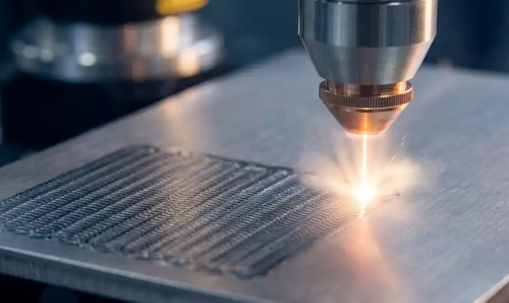
Contaminants like rust, oxides, oils, and coatings typically absorb more strongly at common industrial wavelengths and exhibit lower ablation thresholds than the substrate. Short, high-peak-power pulses raise energy in the contaminant layer above its removal threshold while the substrate stays below its own threshold, so the layer ejects via photothermal evaporation or photomechanical spallation. Peer-reviewed work on rust removal shows that removal quality improves when fluence and repetition are balanced with scan speed—too much energy elevates roughness and risks substrate modification. See the multi-objective rust removal study for carbon steel that details these trade-offs in an open-access format in 2024.
Heat management with pulses and passes
Pulse duration and pass strategy govern the heat-affected zone (HAZ). Nanosecond pulses are common in industry and can be tuned for gentle removal; picosecond/ultrashort pulses further confine heat for sensitive finishes. Practically, you’ll minimize risk by starting with low fluence, higher scan speeds, and multiple light passes rather than a single aggressive sweep. Defocus, standoff, and overlap also modulate peak energy density and should be dialed in before tightening focus.
QA signals for “no damage”
In-line cues include a clean, controlled plume; stable surface reflectivity; and the absence of temper color or micro-melting. If available, optical emission or LIBS monitoring can indicate endpoint: a decline of coating/rust spectral lines with emergence of substrate lines (e.g., Fe, Cr, Ni for stainless) signals that you’re at or near bare metal. Post-pass, verify with profilometry and, where relevant, microscopy to confirm that roughness and texture remain within your target window.
Parameters and setup to prevent damage in laser cleaning for weld prep
All parameter values below are conservative starting windows — validate on coupons for your specific alloy, contaminant, optics, and beam path. The safest path is to bias toward low fluence, fast scan speeds, modest overlap, and multiple passes, then approach the removal threshold gradually while watching QA signals.
Fluence, overlap, speed, focus
- Fluence (J/cm²): Begin just above the contaminant’s removal threshold and below the substrate’s threshold. For gentle weld-prep cleaning, initial trials often sit at the lower end of published ranges; step upward only as needed to complete removal.
- Overlap and hatch: Use modest line and pulse overlap to avoid striping while limiting local heat build. Increase overlap only after dialing in fluence and speed.
- Scan speed (m/s): Start faster to keep the heat load down; slow incrementally if removal is incomplete. Pair speed changes with repetition rate to maintain similar pulse-to-pulse spacing.
- Focus and standoff: Slight positive defocus or increased standoff can reduce peak fluence and even out energy density; tighten focus later when your safe window is documented.
Pulse regime and repetition
- Regime: Nanosecond pulsed fiber sources are common for industrial cleaning; consider picosecond when sensitive finishes demand minimal HAZ. Shorter pulses confine heat but may require different optics and cost trade-offs.
- Repetition rate (kHz): Higher repetition reduces per-pulse energy at a given average power and increases overlap at a fixed speed, which can help achieve uniform, gentle removal. Tune rep rate, pulse energy, and speed together so that net fluence per unit area stays within the validated safe band.
Pass strategy and verification
- Multi-pass approach: Use several quick passes instead of one hot pass; inspect between passes to avoid overshoot.
- Witness coupons and parameter matrices: Run small sweeps varying one parameter at a time. Log plume behavior, surface appearance, and Ra after each condition.
- Verification: For weld prep, verify roughness against your process KPI (e.g., Ra ≈ 1.2–2.5 µm) using a stylus or optical profilometer. Document lighting conditions for consistent photographs. For coating tasks, plan downstream adhesion and salt tests after recoating.
Material-specific tuning
Alloys respond differently due to absorptivity, reflectivity, thermal diffusivity, and native oxide behavior. Use this decision logic to bias your starting point, then validate and lock settings per material/contaminant pair.
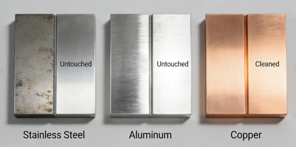
Steels and stainless
Steel and stainless oxides absorb well relative to the base metal, which eases selective removal. Start with moderate per-pulse energy, higher repetition rates, and moderate-to-faster scan speeds to keep the heat moving. Watch for temper color, micro-melting, or roughness spikes—signs you’ve crossed into substrate modification. Confirm the absence of discoloration and verify Ra against your KPI range before releasing to production welding.
Aluminum and copper
Aluminum and copper are highly reflective with high thermal diffusivity, so the substrate tends to shed heat quickly but also demands careful thresholds. Bias toward lower per-pulse fluence, relatively fast scans, and conservative overlap. For aluminum, consider an inert purge or quick post-clean protection where re-oxidation affects downstream welding or bonding. For copper, if cleaning is required, keep passes light and fast; ultrashort pulses can reduce HAZ risk if available.
Titanium and sensitive finishes
Titanium’s oxide absorbs but the substrate can show surface modifications and periodic structures if fluence is too high. Use near-threshold fluence, high repetition, and multiple light passes. Confirm with profilometry and, when risk is high, microstructural checks under magnification before committing to production.
Weld prep and paint strip process
Laser cleaning for weld prep benefits from a disciplined SOP that controls energy input and verifies surface readiness before the arc ever starts. Here’s the deal: when you stabilize standoff, keep passes light, and check Ra as you go, weld defects tend to drop.
Pre-checks and fixtures
- Validate access to joint geometry and confirm masking needs for adjacent surfaces.
- Stabilize standoff and incident angle with rigid fixtures to maintain uniform energy density and overlap.
- Check enclosure condition, interlocks, and emergency stop function. For service or setup inside the enclosure, apply full lockout/tagout procedures per OSHA 29 CFR 1910.147.
- Set up local exhaust ventilation (LEV) close to the plume to capture particulates and gases; verify capture velocity as part of startup checks.
Scan paths and coverage
- Use consistent hatch patterns with modest overlap; adjust line spacing to avoid striping.
- Favor multiple quick passes; inspect for clean metal without temper color between passes.
- For edges, radii, and bevels, reduce speed slightly and verify that beam incidence maintains coverage without oversaturating hotspots.
Post-clean QA for weld/coat
- Weld readiness: Measure Ra at representative points; aim to keep your distribution within the process window you’ve validated (for example Ra ≈ 1.2–2.5 µm for a given alloy and welding process such as GMAW or GTAW). Track weld defect rates (porosity, inclusions, lack of fusion) before and after adoption to prove effectiveness.
- Coating readiness (when paint strip is involved): After recoating, verify adhesion using the cross-cut method per the ASTM D3359 procedure; grades of 4B–5B indicate strong adhesion when the coating system supports it. Where corrosive exposure is a concern, sample soluble salts using the ISO 8502 Bresle method and confirm results against your coating system limits.
For background on the adhesion method, see the concise practitioner guide to the ASTM D3359 cross-cut test published by a well-known instrument maker (PDF). For Bresle sampling, review a reputable user guide that summarizes ISO 8502-6/9 patch extraction and conductivity measurement steps.
Safety and compliance essentials
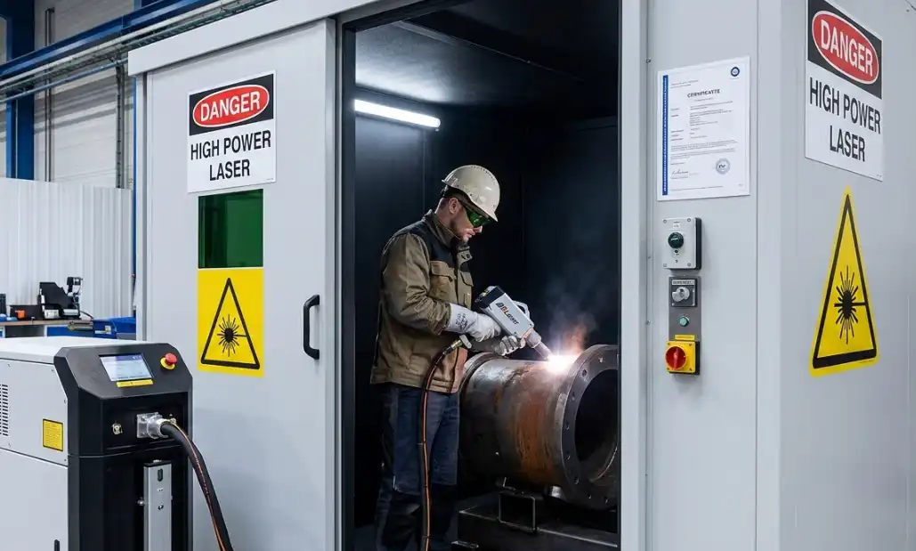
Class 4 controls to Class 1
Operate under an ANSI Z136.1-aligned program. Appoint an LSO to conduct hazard evaluations, define the nominal hazard zone (NHZ), and approve engineered and administrative controls. Aim to run an embedded Class 4 source under Class 1 conditions in normal use with a light-tight enclosure, fail-safe door interlocks, and appropriate signage. Reserve open-beam or access-required modes for maintenance with heightened controls. For an accessible overview of these program elements, consult a national laboratory’s laser safety manual that summarizes ANSI-aligned requirements.
Eyewear, enclosures, extraction
- Eyewear: Select optical density (OD) matched to wavelength and anticipated exposure so transmitted irradiance is below the maximum permissible exposure (MPE). Eyewear must be labeled with OD and wavelength; the LSO approves selections. A university EHS laser safety guideline offers a practical OD selection overview aligned with ANSI principles.
- Enclosures and interlocks: Treat interlocks as fail-safe and test them routinely. Keep viewing windows appropriately rated and labeled.
- Fume capture: Place movable capture hoods as close as practical to the plume. Validate capture with airflow measurements and align filtration to the contaminant profile; consult NIOSH/ACGIH guidance and your industrial hygienist for exposure limits and sampling plans. One NIOSH Health Hazard Evaluation provides a real-world example of exposure assessment and control recommendations in a metalworking setting.
Training, SOPs, documentation
- PPE (OSHA 29 CFR 1910 Subpart I): Complete and document a hazard assessment; provide and train on required PPE; maintain records. OSHA’s PPE assessment resources outline employer duties and documentation expectations.
- LOTO (OSHA 29 CFR 1910.147): For servicing and maintenance, isolate and lock out hazardous energy, dissipate stored energy (e.g., capacitors), and verify zero-energy state before work begins. OSHA’s program directive offers detailed guidance on program elements and inspections.
- Documentation: Maintain SOPs, training logs, interlock test records, LEV inspection data, air sampling results, and incident response procedures.
Conclusion
Key takeaways: Start with low fluence and high scan speed, use multiple quick passes, and verify on coupons. For laser cleaning for weld prep, manage toward a roughness window like Ra ≈ 1.2–2.5 µm suited to your alloy and welding process, and prove value with a measurable drop in weld defects. When stripping paint, confirm performance after recoating via adhesion testing (seeking ≥4B–5B where applicable) and, where needed, soluble salt checks per ISO 8502. Document tuned parameter windows for each alloy/contaminant pair and keep photographic and metrology records.
Next steps: Pilot on representative coupons, then small batches. Lock SOPs under an ANSI Z136.1 program with OSHA-aligned PPE and LOTO controls, and work with EHS/IH to validate LEV and exposure. Benchmark laser cleaning against abrasive or chemical methods for throughput (m²/h), waste, and surface quality, and choose the process that meets your quality objectives with the best total cost of ownership.
Inline sources (descriptive anchors):
- Multi-objective rust removal study on carbon steel (2024) discussing parameter trade-offs and roughness effects: https://pmc.ncbi.nlm.nih.gov/articles/PMC11242286/
- National lab EHS manual summarizing ANSI Z136.1 program elements and controls: https://ehs.lbl.gov/resource/esh-manual-pub-3000/ch16/
- University EHS laser safety guideline with OD selection notes: https://ehs.umich.edu/wp-content/uploads/2025/02/Laser-Safety-Guideline.pdf
- OSHA PPE hazard assessment overview (Subpart I): https://www.osha.gov/training/library/personal-protective-equipment/assessment
- OSHA lockout/tagout program directive (1910.147): https://www.osha.gov/sites/default/files/enforcement/directives/ADM_04-00-003.pdf
- NIOSH Health Hazard Evaluation example for exposure assessment and controls: https://www.cdc.gov/niosh/hhe/reports/pdfs/2019-0215-3371.pdf
- ASTM D3359 adhesion test (standard abstract): https://www.astm.org/d3359-23.html
- ISO 8502 Bresle method user guide (overview): https://downloads.elcometer.com/PDFs/InstructionManuals/MultiLingual/138_Kits_NEW.pdf


