Laser welding can be fast, precise, and repeatable—but some metals are naturally easier than others. This beginner‑friendly guide gives you a practical way to decide if a part is a good candidate, what defects to expect, and how to set safe, evidence‑informed starting parameters for stainless, carbon, and galvanized steel, with short notes on aluminum, copper/brass, titanium, and nickel alloys. You’ll see parameter windows, a troubleshooting flow, and checklists tied to recognized standards and authoritative references.
Key takeaways
- Metals suitable for laser welding depend on absorptivity, thermal conductivity, coatings (e.g., zinc), and alloy cracking tendency.
- Stainless and low‑carbon steels are generally excellent/good candidates; galvanized steels are feasible but require venting and pool‑stability tactics to control porosity.
- Start with clean joints, stable keyhole mode, argon shielding, and small beam oscillation (wobble) only when needed; validate with macro/NDT against the specified ISO quality level.
- For galvanized lap joints, zinc vapor is the main porosity driver—use intentional venting paths or fit‑up gaps, consider oscillation, and escalate to hybrid laser‑arc if needed.
- Always control fumes and laser hazards per safety guidance (LEV, PPE, eyewear); qualify procedures per ISO/ANSI/AWS frameworks and check acceptance vs ISO 13919‑1.
Quick decision checklist: How to judge metals suitable for laser welding
Answer these three questions:
- Material and thickness: Is it stainless/carbon steel ≤6 mm, or galvanized ≤3 mm? If yes, likely suitable; if aluminum/copper/brass, proceed but expect tighter windows and more tuning.
- Joint design and access: Can you achieve good fit‑up and provide a gas‑escape path for coatings (e.g., galvanized lap)? If not, redesign or consider hybrid/alternate process.
- Quality target and inspection: Do you have acceptance criteria (e.g., ISO 13919‑1 level B/C/D) and a way to verify (macro/NDT)? If not, define them before welding.
If you said yes to all three, you’re ready for controlled trials. If not, adjust design or process first.
Safety and prep essentials you can’t skip
- Fumes: Stainless welding fumes can contain hexavalent chromium; galvanized produces zinc oxide. Use local exhaust ventilation (LEV), appropriate respiratory protection when required, and follow welding safety practices. See OSHA’s laser safety pages and HSE fume references for stainless and galvanized controls.
- OSHA overview: see the guidance on laser hazards and applicable standards in the United States: OSHA laser hazards and standards.
- HSE references: stainless (Cr(VI)) and galvanized fume control material: HSE stainless fume reference SSWF‑1 and HSE galvanized fume reference MSWF‑1.
- Shielding gas handling: Treat inert gases and cylinders per welding safety. See AWS Z49.1 welding safety.
- Laser hazards: Class 4 fiber lasers demand eyewear and controls per ANSI/OSHA. See OSHA link above.
- Surface prep: Remove oils, oxides, coatings in the joint area as specified; consistent edge quality and standoff matter.
Beginner glossary (fast reference)
- Keyhole mode: A vapor cavity forms, concentrating energy for deeper penetration; sensitive to stability.
- Conduction mode: No persistent keyhole; shallow, wide beads at lower energy density.
- Wobble (oscillation): Small circular/linear beam motion to stabilize the pool and bridge gaps.
- Linear energy: Power divided by travel speed (J/mm), a useful sanity metric.
- HAZ: Heat‑affected zone adjacent to the weld.
- Acceptance level: Imperfection limits per ISO 13919‑1 (levels B/C/D) for electron/laser beam welds in steels.
Stainless steel (304/316): excellent candidate with clean prep and stable shielding
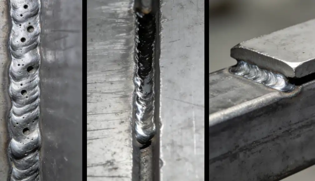
Stainless sheet in the 0.8–6 mm range is broadly well‑suited to fiber laser welding when fit‑up and gas shielding are controlled. Typical defects are porosity (from contamination or instability), undercut at excessive speed, and occasional hot‑cracking risk in certain chemistries. TWI identifies porosity and solidification cracking among the main laser weld defects, and procedure acceptance for steels commonly references ISO 13919‑1 levels. See TWI’s defect overview and the ISO qualification/acceptance framework for context.
- Defect context: TWI on typical laser weld defects.
- Qualification/acceptance context: ISO 15614‑11 procedure qualification (preview) and ISO 13919‑1 acceptance levels (OBP).
Starter parameter windows (validate on your equipment; examples reflect shop‑floor practice and peer‑reviewed anchors):
- Shielding: Start with high‑purity argon, 12–20 L/min, nozzle angled with travel; switch to Ar/He mixes if you need deeper penetration/stability.
- Focus: At or slightly below the surface for ≥2 mm; adjust in 0.2–0.5 mm steps.
- Wobble: Off initially; add small circular 0.3–0.8 mm at 50–150 Hz only if pool stability or gap‑bridging is needed (oscillation has been shown to reduce porosity in laser welding studies).
- Speed/power sanity: Peer‑reviewed work on austenitic stainless shows full‑penetration potential around 1.5–3 kW and ~1–3 m/min depending on thickness, focus, and optics. See examples in Bayock 2022 and Alhajhamoud 2022 for trend anchors.
Stainless starter table (0.8–6 mm)
| Thickness (mm) | Power (kW) | Speed (m/min) | Focus (mm) | Wobble (amp mm / Hz) | Shielding gas |
|---|---|---|---|---|---|
| 0.8–1.0 | 1.0–1.6 | 2.0–3.5 | 0 to −0.3 | Off or 0.3 / 80–120 | Ar 12–16 L/min |
| 1.5–2.0 | 1.5–2.5 | 1.5–3.0 | −0.2 to −0.6 | Off or 0.3–0.6 / 60–120 | Ar 14–20 L/min |
| 3.0–4.0 | 2.0–3.5 | 0.8–1.8 | −0.4 to −1.0 | 0.4–0.8 / 50–100 if needed | Ar or Ar/He |
| 5.0–6.0 | 3.0–5.0 | 0.4–1.2 | −0.6 to −1.2 | 0.5–1.0 / 40–80 if needed | Ar/He mix |
Troubleshooting quick‑hits
- Porosity: Reclean, reduce speed slightly or increase power to stabilize keyhole; trial small wobble; consider Ar/He mix. Verify with macros vs ISO 13919‑1 target level.
- Undercut/underfill: Reduce speed or increase wobble amplitude modestly; adjust focus closer to surface.
- Incomplete penetration: Increase power, reduce speed, or shift focus slightly deeper; verify with test sections.
Carbon/low‑carbon steel: good candidate with attention to cleanliness and focus
Low‑carbon steel sheets (0.8–6 mm) laser‑weld well with narrow HAZ and good productivity when edges are clean and focus is set for stable keyhole mode. Typical issues are lack of fusion (poor focus/contamination), undercut from excessive speed, and porosity from contaminants. Hydrogen cracking risk rises with higher carbon equivalent or restraint, but this risk is more typical of thicker sections and arc processes; be aware in special cases. See TWI’s hydrogen cracking overview for prevention context.
- Risk context: TWI on hydrogen cracks in steels.
Carbon steel starter table (0.8–6 mm)
| Thickness (mm) | Power (kW) | Speed (m/min) | Focus (mm) | Wobble (amp mm / Hz) | Shielding gas |
|---|---|---|---|---|---|
| 0.8–1.0 | 1.0–1.6 | 2.0–3.5 | 0 to −0.3 | Off or 0.3 / 80–120 | Ar 12–16 L/min |
| 1.5–2.0 | 1.5–2.5 | 1.5–3.0 | −0.2 to −0.6 | Off or 0.3–0.6 / 60–120 | Ar 14–20 L/min |
| 3.0–4.0 | 2.0–3.5 | 0.8–1.8 | −0.4 to −1.0 | 0.4–0.8 / 50–100 if needed | Ar or Ar/He |
| 5.0–6.0 | 3.0–5.0 | 0.4–1.2 | −0.6 to −1.2 | 0.5–1.0 / 40–80 if needed | Ar/He mix |
Tips
- Keep edges bright and dry; wipe with solvent compatible with your procedure.
- Start with wobble off; add small oscillation if you see spatter/instability or need minor gap‑bridging.
- Verify bead shape and penetration on coupons before production.
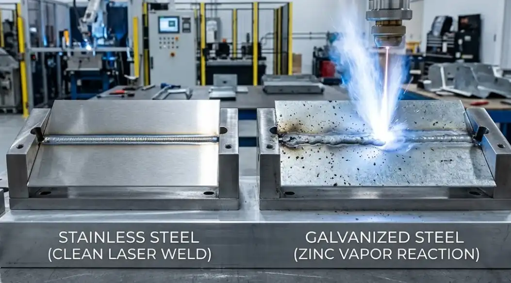
Galvanized steel: feasible with venting, fit‑up control, and pool stabilization
Why it’s tricky: Zinc on galvanized sheet vaporizes at a lower temperature than steel, and in lap joints the trapped vapor can create porosity or severe blow‑holes. TWI explicitly documents this defect mode in laser‑welded lap joints of zinc‑coated steels. Acceptance and qualification for steels follow ISO 15614‑11 referencing ISO 13919‑1 imperfection levels.
- Mechanism: TWI on laser weld defects, including blow‑holes in zinc‑coated lap joints.
- Qualification/acceptance context: ISO 15614‑11 (preview) and ISO 13919‑1 (OBP).
- Feasibility evidence and energy window: An automotive galvanized steel study achieved high strength and ISO 13919‑1 level B quality by controlling linear energy within roughly 30–90 J/mm for ~1.2 mm sheet. See Górka et al., 2023.
- Oscillation as a mitigation lever: High‑frequency beam oscillation has been shown to stabilize keyholes and reduce porosity in laser welding experiments; use as a parameter to test in galvanized trials. See 2024 oscillation study on porosity reduction.
- Hybrid option: If porosity persists, laser‑arc hybrid welding increases tolerance to gaps and promotes gas escape/penetration. See ISO 23493 laser‑arc hybrid welding definition.
Galvanized starter table (lap joints typical, 0.8–3.0 mm)
| Thickness (mm) | Linear energy (J/mm) | Example power/speed | Focus (mm) | Wobble (amp mm / Hz) | Fit‑up notes |
|---|---|---|---|---|---|
| 0.8–1.0 | 30–70 | 1.2 kW @ 2.0–3.0 m/min | 0 to −0.3 | 0.3–0.6 / 60–120 | Aim 0.2–0.4 mm gap or vent slots where design allows |
| 1.2–1.6 | 40–90 | 1.5–2.5 kW @ 1.0–2.5 m/min | −0.2 to −0.6 | 0.4–0.8 / 60–120 | Clean edges; consistent clamping; test venting |
| 2.0–3.0 | 60–120 | 2.5–4.0 kW @ 0.8–1.8 m/min | −0.4 to −0.8 | 0.5–1.0 / 50–100 | Consider dual‑pass or hybrid if porosity persists |
Porosity triage (first three checks)
- Confirm venting: Is there a path for zinc vapor? Add a small, toleranced gap or engineered vent slots if allowed.
- Stabilize pool: Trial a small circular wobble and tune frequency; adjust focus slightly and avoid excessive speed spikes.
- Gas discipline: Ensure steady argon shielding (12–20 L/min) with correct standoff and direction; avoid turbulence.
Short notes on other alloys
- Aluminum (5xxx/6xxx): High reflectivity and oxide films challenge coupling; porosity and hot cracking (notably in 6xxx) are common risks. Use spotless prep, consider Ar/He mixes, trial wobble for keyhole stability, and select filler (e.g., 4043 for some 6xxx applications) when wire‑fed laser is available. See TWI’s aluminum guidance: TWI on welding aluminium.
- Copper/brass: Very high reflectivity and thermal conductivity demand higher power density, careful focus, and often He‑rich shielding; alternative wavelengths or hybrid processes may be more robust depending on geometry. See TWI context on reflective metals: TWI cutting knowledge on reflective materials.
- Titanium: Excellent laser weldability with strict inert shielding; use trailing shields or enclosures to prevent contamination.
- Nickel alloys: Generally weldable with appropriate cleanliness and heat input control; composition and strengthening mechanism affect crack susceptibility. Overview: TWI on nickel and nickel alloys.
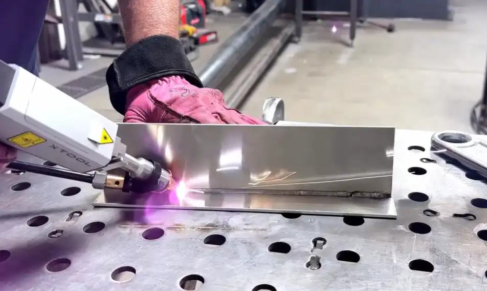
Practical example: reducing galvanized lap porosity with wobble and venting
In a 2.0 mm galvanized lap joint trial using a handheld fiber laser, begin near the lower end of the energy window: linear energy ~40–60 J/mm (e.g., 1.6 kW at 1.6–2.4 m/min), focal offset −0.3 to −0.5 mm. Set a small circular wobble about 0.5 mm amplitude at 50–100 Hz and maintain argon shielding at ~12–18 L/min with the nozzle angled along travel. Where the design permits, hold a 0.3–0.6 mm intentional gap or provide vent slots so zinc vapor can escape. Inspect cross‑sections for porosity; if present, increase wobble amplitude slightly, adjust speed to stabilize the keyhole, or evaluate a trailing gas shoe. For persistent issues, consider laser‑arc hybrid per ISO 23493.
Trial log template (copy and use on coupons before production)
| Date | Material/grade | Thickness (mm) | Joint type | Torch angle | Power (kW) | Speed (m/min) | Focus (mm) | Wobble (amp mm / Hz) | Shielding gas & flow | Observed defects | Macro/NDT result |
|---|---|---|---|---|---|---|---|---|---|---|---|
| 2026- | 304 SS / DC04 / GI | Butt / Lap / Fillet |
DOE starter (power vs speed, 3×3 on a fixed thickness)
| Run | Power (kW) | Speed (m/min) | Notes |
|---|---|---|---|
| 1 | Low | Low | Baseline bead shape |
| 2 | Low | Med | |
| 3 | Low | High | |
| 4 | Med | Low | |
| 5 | Med | Med | |
| 6 | Med | High | |
| 7 | High | Low | |
| 8 | High | Med | |
| 9 | High | High |
Troubleshooting quick‑reference flow
- See porosity? → Reclean → Add/verify vent path (galvanized) → Stabilize with small wobble → Tune focus −0.2 to −0.6 mm → Adjust speed/power slightly → Verify with macro against ISO level.
- See undercut/spatter? → Reduce speed a bit → Increase wobble amplitude modestly → Bring focus closer to surface → Confirm gas flow isn’t too high (turbulence).
- Lack of penetration? → Increase power or reduce speed → Shift focus slightly deeper → Re‑clamp for fit‑up.
When to escalate
Thick sections beyond your equipment’s stable keyhole capability, persistent porosity in galvanized despite venting/oscillation, highly reflective copper‑heavy parts with limited power density, or stringent metallurgical requirements: consider wire‑fed laser, laser‑arc hybrid welding, alternate wavelengths, or engage a welding specialist. Framework and definitions: ISO 23493 laser‑arc hybrid welding.
References and further reading
- Defects and mechanisms: TWI — What are the typical defects in laser welds? (accessed 2026) — notes on porosity, cracking, and galvanized lap blow‑holes.
- Qualification and acceptance: ISO 15614‑11 procedure qualification (preview); ISO 13919‑1 acceptance levels (OBP).
- Galvanized feasibility and energy window: Górka et al., 2023 — Laser beam welding of galvanized car body steel.
- Oscillation and porosity trends: Effect of beam oscillation frequency on porosity (2024 study).
- Safety: AWS Z49.1 welding safety; OSHA laser hazards and standards; HSE stainless fume reference SSWF‑1; HSE galvanized fume reference MSWF‑1.
- Material notes: TWI — Aluminium welding FAQ; TWI — Cutting processes: laser cutting of reflective metals; TWI — Weldability of nickel and nickel alloys.
Author: Manufacturing Process Engineer — Laser Welding Specialist. Editorially reviewed for technical accuracy against the cited sources.


