Introduction
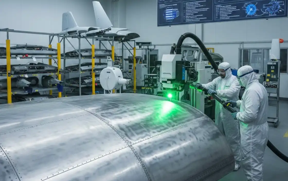
For MRO maintenance and process engineering managers, the goal of paint removal is simple: take coatings off fast, leave the aluminum untouched, and keep pilots, technicians, and auditors happy. Laser paint stripping is often the right choice when you need precise, dry, and highly controllable removal of polyurethane topcoats and epoxy primers on aluminum skins and structures—especially where chemical use is constrained or media blasting risks foreign object debris (FOD) and profile damage. Choose laser over chemical or media when you need tight process control, low consumables and waste, selective removal (maskless), or when hangar ventilation and hazardous air pollutant limits are tight. In this guide you’ll learn: which laser/optics to use, safe starting parameter windows and scan strategy, how to verify cleanliness and adhesion readiness, and how to meet safety and environmental requirements while standing up a production-ready process.
Parameters and setup
Laser type and optics
For aerospace aluminum, pulsed near‑infrared sources are standard because paint absorbs strongly while bare aluminum reflects more. A Class 4 pulsed fiber laser at ~1064 nm paired with a galvo scanner provides uniform energy delivery and high throughput across large skins and access panels. Use an F‑theta lens with a working field appropriate to your part size (e.g., 160–300 mm field for benches; larger for gantry cells). Select a spot diameter that balances resolution and productivity—typically 100–300 µm at focus—then set hatch/overlap to achieve consistent coverage without hot spots. Favor top‑hat or near‑flat intensity profiles for even ablation; if using Gaussian beams, compensate with overlap and multi‑pass recipes. Keep the optical train clean: purge or positive pressure on the scan head window, and align the fume capture close to the interaction zone to protect optics and contain plume.
Starting windows and scan strategy
Start conservatively on mixed and multi‑generation stacks (legacy chromated epoxy + polyurethane, newer non‑chrome primers, sol‑gel pretreatments) to avoid thermal imprinting on 2xxx/7xxx and Al‑Li substrates. The principle: low fluence, shorter pulses, higher scan speed, and multiple light passes with generous overlap. Validate on coupons before touching aircraft hardware.
Neutral micro‑recipe example (for qualification on mixed stacks — illustrative, not universal; finalize via DOE and metallography):
- Source: pulsed fiber, 1064 nm; pulse duration 100–200 ns.
- Spot size at focus: ~200 µm; hatch overlap: 60–70%.
- Fluence: begin around 0.5–1.2 J/cm²; creep up in 0.1–0.2 J/cm² steps as needed.
- Scan speed: 800–1,500 mm/s; adjust to keep plume stable and substrate temperature controlled.
- Pass strategy: 2–6 light passes rather than 1–2 heavy passes; alternate hatch angles (e.g., 0°/90°) to reduce ridging.
- Standoff/defocus: ±0–0.5 mm around best focus to broaden spot very slightly if needed for smoother edges.
- Indicators: Listen/observe for sparkless ablation with a fine, steady plume; stop if you see bright specular flashes (risk of substrate interaction) or color shifts suggesting heat tinting.
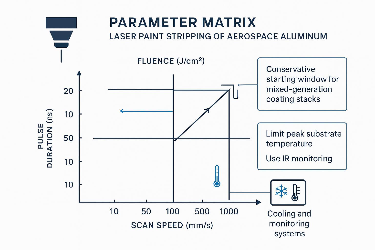
Protocol for tuning: qualify a window on coupons representative of the hardest‑to‑strip stack in your fleet, log removal completeness per pass, and capture IR temperature/time traces. Increase fluence last; first optimize overlap, speed, and pass count. For selective removal (e.g., topcoat only), bias to shorter pulses and lower fluence, accepting extra passes. Always finish with a light “polish” pass to even the surface before pre‑treatment or primer.
Thermal control and monitoring
Thermal discipline protects fatigue performance. Use an IR pyrometer or calibrated IR camera aimed near the interaction zone; record peak and dwell temperatures alongside parameters. Set interlocks that pause the scan if peak temperature exceeds your site’s limit (often held ≤100–120°C pending metallurgical validation). Add air‑assist directed across the plume to improve heat removal and plume capture without disturbing the beam. Monitor plume opacity as a proxy for process stability; rising opacity at steady parameters may indicate filter loading or standoff drift. Document all sensor calibrations and retain traces with the work order.
QA and acceptance
Surface cleanliness verification
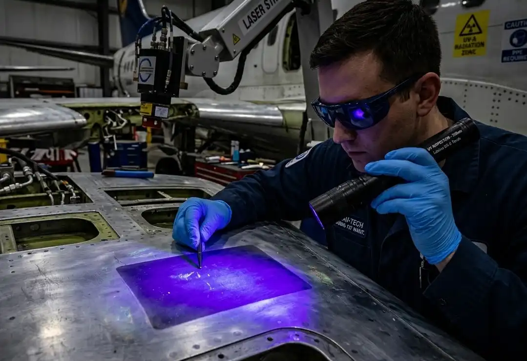
Confirm complete coating removal and residue control before pretreatment. Combine visual inspection under white light with raking light and, where practical, UV‑A to reveal residual organic films. Perform a solvent wipe and check for discoloration or fluorescent residue transfer. For critical hardware, consider adapting aerospace cleanliness verification practices such as particulate and nonvolatile residue checks used in precision programs to demonstrate a clean surface state prior to pretreatment, aligning documentation discipline with aerospace cleanliness standards discussed by NASA in its cleanliness verification guidance described in the rocket engine fluid systems cleanliness standard.
Roughness and wettability targets
Post‑strip texture should support primer adhesion at least equivalent to OEM pretreatment baselines. Track Ra/Rz via stylus profilometry; for aluminum skins a low‑microroughness finish is typical after laser stripping. Verify wettability via water‑break‑free testing and, where available, static contact angle—values trending below roughly 60° generally indicate a clean, high‑energy surface suitable for adhesion; set site‑specific limits during qualification. Record values by zone, not just by panel, to catch local hot‑spot effects.
Adhesion and fatigue validation
Recoat adhesion must be proven on stripped coupons. Conduct pull‑off adhesion per ASTM D4541 after full cure of the recoated system, and supplement with ASTM D3359 for qualitative crosshatch if relevant to your OEM spec. For structural risk assessment, perform comparative high‑cycle fatigue on baseline vs. laser‑stripped‑and‑recoated coupons (e.g., per ASTM E466) when parts are in fatigue‑sensitive locations or when thermal exposure approached your limit during stripping. Document acceptance criteria before production release and tie failures to corrective actions (parameter rollback, added passes, revised pretreatment).
Safety and compliance
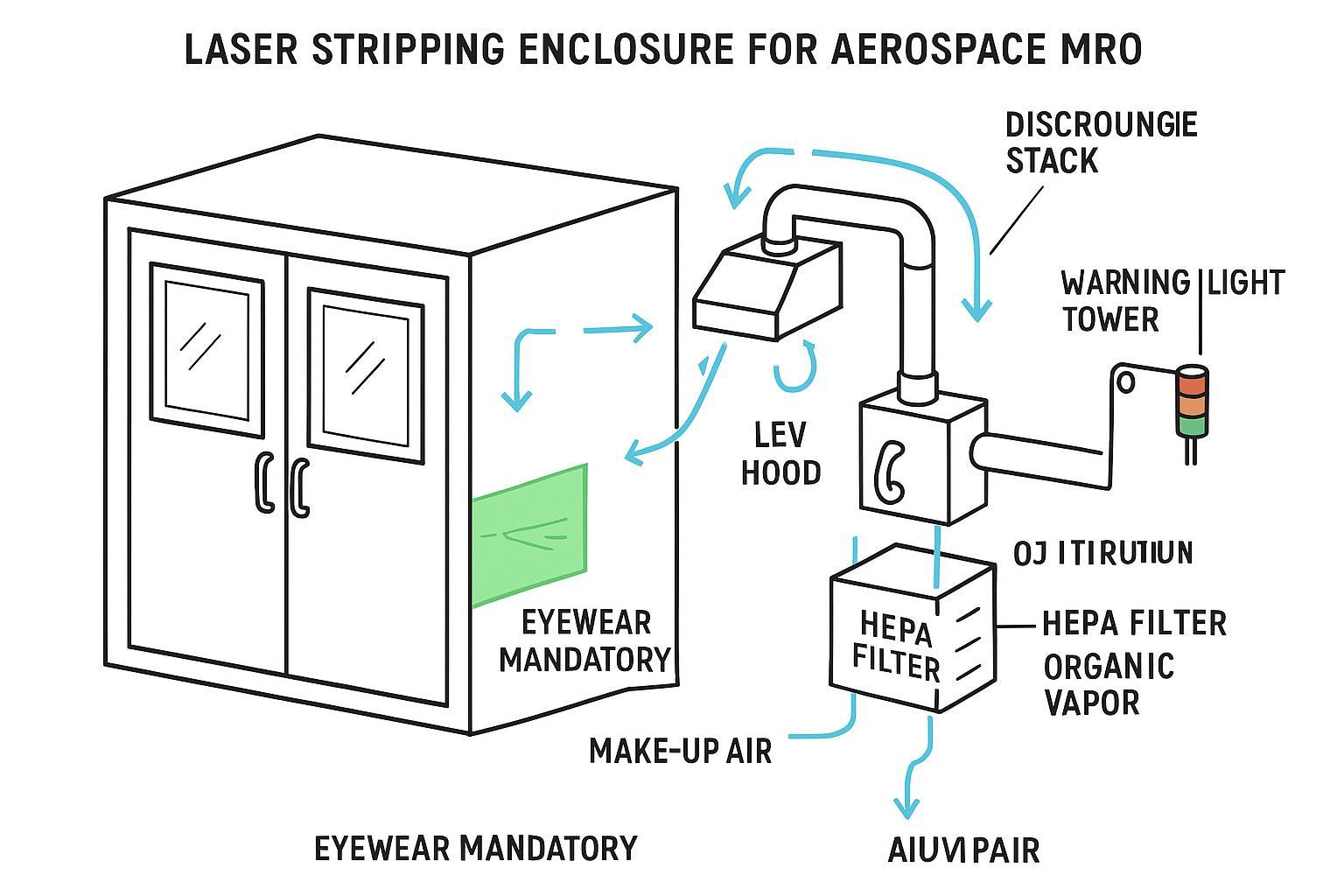
Laser safety controls and training
Treat the process as a Class 4 laser operation within a fully enclosed, interlocked cell. Appoint an LSO, define a controlled area, and implement engineering controls: interlocked access, emergency stops, key control, warning lights, and protective housings. Provide wavelength‑appropriate eyewear and task‑appropriate skin protection, with training and authorization by role. According to the ANSI Z136.1 overview, these control measures and hazard evaluations are foundational to safe use programs, and OSHA’s laser hazards resources align to this framework for workplace implementation.
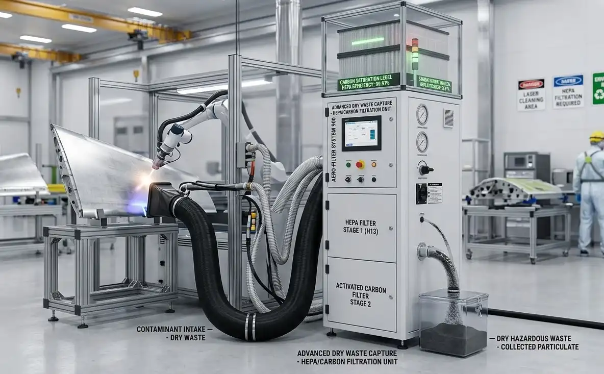
LGAC capture and ventilation
Laser‑generated airborne contaminants (LGAC) include fine particulates and organic vapors from ablated coatings. Design local exhaust ventilation (LEV) to capture the buoyant plume at the source; verify capture using industrial hygiene methods and maintain airflow with pressure‑drop monitoring across filters. HEPA filtration addresses particulates; activated carbon can adsorb organics depending on the coating chemistry. OSHA’s ventilation guidance outlines capture and verification concepts that can be adapted to laser ablation plumes in enclosed cells, and ACGIH industrial ventilation resources provide engineering principles for capture velocity and hood design.
EPA air and waste requirements
U.S. aerospace MRO facilities fall under the National Emission Standards for Hazardous Air Pollutants (NESHAP) Aerospace Manufacturing and Rework rule (40 CFR 63 Subpart GG). Determine applicability, maintain required records, and ensure that any hazardous air pollutants from associated cleaning or coating operations are controlled. While laser stripping can reduce methylene chloride use compared with chemical stripping, you must still manage emissions, captured dust, spent filters, and solvent wipes per your permit and waste profiles. Consult the codified Subpart GG text and EPA’s program summary for scope, definitions, recordkeeping, and compliance pathways.
Method comparison
Versus chemical stripping
Chemical stripping can remove large areas without specialized optics, but it introduces hazardous chemicals, waste streams, longer dwell times, and potential attack on sealants or sensitive substrates if controls slip. Laser stripping eliminates liquid chemical handling at the point of use, allows selective removal without masking, and simplifies rework cycles—at the expense of higher capital equipment and the need for an interlocked enclosure with ventilation and filtration.
Versus media blasting
Media blasting (plastic, walnut, or other soft media) is familiar and scalable but risks embedding media, altering surface profile, creating dust/FOD risks, and driving extensive containment requirements. Lasers avoid impact damage and reduce FOD risk when operated in closed cells, with process logs offering stronger traceability. However, lasers demand parameter discipline and operator training to avoid thermal artifacts.
Throughput, cost, and waste tradeoffs
A practical way to compare methods is to look at removal rate, consumables, labor, and waste handling.
| Factor | Chemical | Media blasting | Laser |
|---|---|---|---|
| Typical consumables | Strippers, neutralizers, wipes | Media, nozzles, masking | Filters (HEPA/carbon), lenses/windows |
| Waste streams | HAP liquids, rinses, wipes | Spent media, dust | Captured particulates, adsorbed organics |
| Containment | High (chemical booths) | High (blast rooms) | Enclosed laser cell |
| Traceability | Batch logs | Limited unless instrumented | Full parameter/sensor logs |
| Capex | Low–medium | Medium | Medium–high |
Illustrative ROI thought experiment: If chemical stripping produces 2–3 lb of hazardous waste per ft² across prep/neutralization, while a properly engineered laser cell generates primarily dry particulate captured on HEPA and adsorbed organics on carbon, the waste‑disposal delta plus reduced masking labor can offset part of the equipment cost over time. Treat any payback analysis as site‑specific and validate with your own removal rates and disposal fees.
Implementation roadmap
Qualification matrix and coupons
Build a qualification matrix that spans your alloys (2024‑T3, 7075‑T6, Al‑Li where applicable) and coating stacks (legacy chromated epoxy + polyurethane, non‑chrome primer systems, sol‑gel pretreatments, and mixed‑generation repaints). For each combination, run a DOE across fluence, pulse duration, scan speed, overlap, and pass count. Inspect for complete removal, check surface via profilometry and water‑break/contact angle, and metallographically screen for heat‑affected signatures. Recoat and test adhesion (ASTM D4541/D3359) and, for fatigue‑sensitive use cases, coupon fatigue (e.g., ASTM E466). Capture all data with traceable parameter logs.
Production controls and SPC
In production, track leading indicators and stability metrics: removal completeness per pass, peak substrate temperature, plume opacity (or optical backscatter), LEV static pressure/flow, and filter pressure drop. Use SPC: X̄‑R on contact angle by zone, p‑chart on rework incidence, and CUSUM on LEV static pressure to catch gradual ventilation degradation. Define action limits tied to hold points (e.g., filter changeout, parameter rollback) and conduct periodic MSA on measurement tools.
Documentation and training
Issue SOPs for parameter setup, thermal monitoring, fume capture checks, pre/post clean verification, acceptance testing, and nonconformance handling. Maintain training records by role (operator, maintainer, LSO) and requalify after significant changes. Keep safety files with hazard evaluations, eyewear OD justifications, interlock test logs, and ventilation performance checks alongside environmental records.
Conclusion
Laser paint stripping aerospace aluminum can be safe, repeatable, and audit‑ready when you pair conservative parameters with disciplined QA and a robust safety program. Mitigate risk by qualifying on the hardest mixed stacks first, setting thermal interlocks, proving recoat adhesion on coupons, and instrumenting the cell for plume capture and temperature. Next steps: assemble your coupon matrix, define acceptance criteria, stand up the interlocked cell and LEV, and run a controlled pilot to lock SPC limits before scaling to flight hardware.
Cited sources (inline, descriptive anchors):
- ANSI Z136.1 program context via the overview in “Safe Use of Lasers (2022)” by ANSI: ANSI Z136.1 overview
- OSHA alignment and standards index: OSHA laser hazards resources
- LSO role and program elements summarized by LIA: Laser Safety Officer responsibilities
- Ventilation and air contaminants guidance from OSHA OTM: OSHA ventilation chapter
- EPA Aerospace NESHAP codified rule: 40 CFR 63 Subpart GG
- FAA corrosion control context: FAA AC 43-4B
- Adhesion test standards landing pages: ASTM D4541 and ASTM D3359


