If your next network plan hinges on distance, bitrate, and budget, the single‑mode vs multi‑mode lasers decision will make or break it. Here’s the quick read: single‑mode wins for long‑reach, precision, and coherent techniques; multi‑mode wins for short‑reach affordability and straightforward deployment.
Key takeaways
- Single‑mode lasers typically deliver near‑Gaussian beams with low M² (≈1–1.3), narrow linewidths (kHz–MHz), and long coherence length—ideal for long‑haul links and coherent/OTDR work. See ISO 11146 notes and coherence basics for context via the Newport ISO 11146 beam‑quality guide and Thorlabs coherence tutorial.
- Multi‑mode sources (often VCSELs in datacom) favor short‑reach cost efficiency over OM3/OM4 with standardized SR reaches (70–400 m depending on speed/grade) confirmed across IEEE families and vendor datasheets such as IEEE 802.3 overviews and Cisco/Arista module datasheets.
- Don’t mix fiber types within a single channel: SM optics expect SMF; SR multimode optics expect OM3/OM4. Mixing introduces loss and modal‑mismatch issues.
- For future‑proofing beyond 100G and for coherent systems, prefer single‑mode infrastructure (DR/FR/LR families). For budget‑constrained campus/datacenter runs under a few hundred meters, multi‑mode SR remains compelling.
- Pricing is volatile by region and volume; as a snapshot, even 10G SMF optics (LR, 10 km) have commoditized to sub‑$50 as of Feb 2026, per a public listing from Flexoptix (observed 2026‑02‑04).
Quick verdict by scenario
| Scenario | Winner | Why it wins |
|---|---|---|
| Long‑haul or coherent detection (0.5–10 km+) | Single‑mode | Low modal dispersion; narrow linewidth; standardized DR/FR/LR/ER reaches (IEEE 802.3 families). |
| Short‑reach inside buildings/campuses (≤70–400 m) | Multi‑mode | Lower optics cost; VCSEL‑based SR modules over OM3/OM4 are simple to deploy. |
| Precision sensing, OTDR, interferometry | Single‑mode | Long coherence length; Gaussian beam; stable M² near 1 improving coupling/focus. |
| Large‑area illumination or cost‑per‑port first | Multi‑mode | Higher aggregate power options; relaxed alignment; affordable SR optics. |
| Future‑proof upgrades beyond 100G | Single‑mode | Clear upgrade path across DR/FR/LR families; avoids MMF modal limits. |
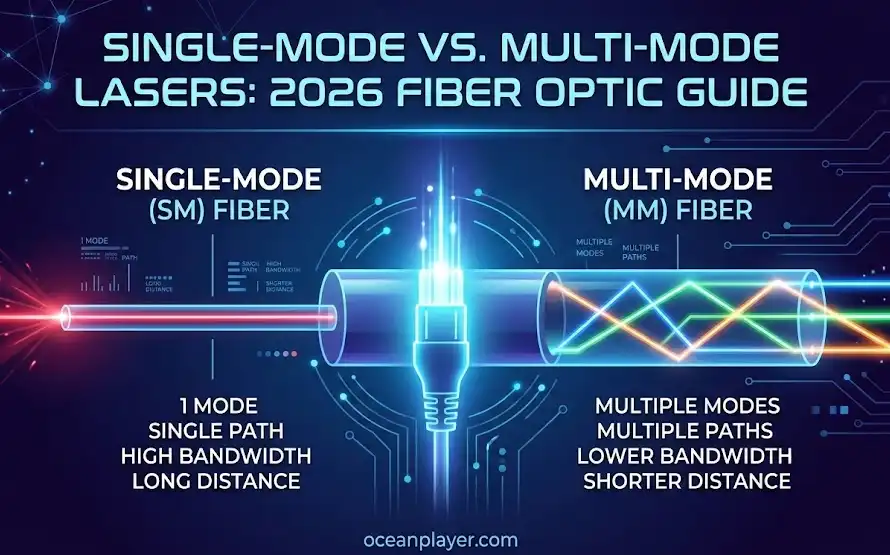
What “single‑mode” and “multi‑mode” mean (with M² and coherence basics)
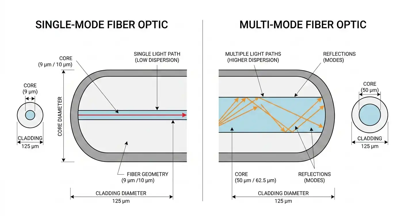
Single‑mode lasers operate in a single transverse spatial mode, producing a near‑Gaussian profile with beam‑quality factor M² close to 1. That means better focusability, lower divergence (after proper collimation), and higher coupling efficiency into ~9–10 μm single‑mode fiber (SMF). ISO 11146 defines how M² is measured through beam‑profiling techniques; for a practical refresher, see the Newport ISO 11146 guide.
Multi‑mode sources (e.g., VCSELs or broad‑area diodes) support multiple spatial modes simultaneously. The beam tends to have higher M² (well above 1, device‑dependent), broader angular content, and larger, sometimes multi‑lobe profiles. That behavior is fine—even advantageous—for coupling into 50/62.5 μm multimode fiber (MMF), which has higher numerical aperture and is more forgiving to alignment.
Coherence and linewidth matter when you need phase stability or narrow spectral content. External‑cavity single‑frequency lasers often specify tens of kilohertz linewidth, and DFBs are commonly in the hundreds of kilohertz to low‑megahertz range, yielding long coherence lengths under Lorentzian assumptions; background formulas appear in the Thorlabs coherence tutorial, while real‑world device examples can be found on Thorlabs ECL/DFB pages.
Head‑to‑head comparison: single‑mode vs multi‑mode lasers
| Dimension | Single‑Mode Lasers (DFB/ECL) | Multi‑Mode Lasers (VCSELs/MM sources) | Notes / Evidence |
|---|---|---|---|
| Beam quality (M²) | ≈1–1.3 (near‑Gaussian) | >>1 (device‑dependent) | ISO 11146 method; SPIE/industry consensus on SLM vs MM beams. Newport ISO 11146 |
| Divergence & focusability | Low divergence after collimation; tight focusing | Broader native spread; larger focus spots | Typical behavior; device specifics vary by optics package |
| Spectral linewidth | kHz–MHz (ECL at tens of kHz; DFB at 100s kHz–MHz) | Broader (multi‑longitudinal for VCSELs; LEDs are nm‑scale) | Thorlabs ECL/DFB references |
| Coherence length | Long (favors coherent/OTDR) | Shorter | Thorlabs coherence tutorial |
| Output power & brightness | High brightness per mode; excellent coupling to SMF | High aggregate power/arrays; easy MMF coupling | Planning depends on radiance vs raw watts |
| Fiber coupling | Optimized for ~9–10 μm SMF; alignment critical; isolators common | Forgiving into 50/62.5 μm MMF; higher NA acceptance | Newport fiber coupling |
| Dispersion & reach | 500 m–10 km+ via DR/FR/LR/ER on SMF | 70–400 m via SR on OM3/OM4 | IEEE 802.3 overview; Cisco/Arista datasheets |
| Noise/stability (RIN, feedback) | Ultra‑low‑RIN options; needs APC/isolators for reflections | Typically higher RIN; generally tolerant of feedback | Thorlabs narrow‑linewidth systems |
| Cost & TCO (indicative) | Higher at ≥100G DR/FR/LR; 10G LR commoditized | Very cost‑effective per port for short reach | Flexoptix 10G LR snapshot, 2026‑02‑04 |
| Ecosystem & upgrades | Clear path across DR/FR/LR/ER families | SR/SR4/SR8/SWDM options dominate short reach | IEEE families; vendor datasheets |
Think of M² like a “focusability score”: closer to 1 means you can form a smaller, cleaner spot, which is why single‑mode beams couple efficiently into tiny SMF cores and hold up over distance.
How to choose (decision tree + migration and TCO notes)
- Need coherent detection, interferometry, OTDR, or any link beyond ~500 m? Choose single‑mode and plan around DR/FR/LR modules.
- Need ≤100–400 m inside a building or campus with strict cost/port targets? Choose multi‑mode SR over OM3/OM4.
- Unsure and want to future‑proof for ≥100G everywhere? Prefer single‑mode cabling; optics may cost more now but simplify upgrades later.
Migration note (MM campus to SM backbone):
- Audit existing trays and trunks (MPO/MTP for MMF vs LC/APC for SMF), plan pull‑paths for OS2 SMF, and stage upgrades floor‑by‑floor. Validate connector types (prefer APC for reflection control) and clean all endfaces before turn‑up.
Lightweight TCO reality check:
- SR optics often win short‑term CAPEX under 400 m. But if you foresee repeated speed bumps (e.g., 40G→100G→400G) or inter‑building runs, SMF’s broader reach matrix and DR/FR/LR availability may reduce re‑cabling and integration risk over 3–5 years. Prices are volatile; always lock quotes close to PO date.
Deeper context for communications planners
Dispersion and bit‑rate–distance
On OM3/OM4, standardized SR reaches taper with speed: common examples are ~300–400 m at 10GBASE‑SR and ~70–100 m at 100GBASE‑SR4 over OM3/OM4, while SMF variants span 500 m (DR), 2 km (FR), and 10 km (LR) classes for 100G and 400G families. See IEEE family summaries and representative vendor datasheets including the IEEE 802.3 consolidated overview and Cisco/Arista reach tables. These distances are grounded in modal vs chromatic dispersion limits and the PHY’s launch/receiver specs.
Coupling and connectors: practical notes
- For SMF, match the Gaussian spot to the mode field and keep back‑reflections low with APC connectors or inline isolators; see the practical guidance in Newport’s fiber‑coupling notes.
- For MMF, ensure the lens NA does not exceed the fiber’s acceptance NA and prefer clean, well‑polished endfaces. A concise NA and acceptance‑angle refresher appears in Thorlabs’ NA tutorial.
Linewidth/coherence: when it truly matters
Coherent detection, phase‑sensitive metrology, and long‑coherence OTDR demand single‑frequency sources with narrow linewidths. External‑cavity lasers at 1550 nm commonly cite ~50–100 kHz linewidths and very low RIN options; DFBs are wider but still far narrower than multimode sources. Tutorial‑level formulas and caveats (lineshape, refractive index) are summarized in the Thorlabs coherence tutorial, with product‑level examples across Thorlabs’ single‑frequency families.
FAQs
- Can you mix single‑mode and multi‑mode fiber or optics in the same link?
- Not within a channel. SR optics are designed for OM3/OM4 MMF; DR/FR/LR/ER optics target SMF. Mixing tends to add loss and dispersion penalties.
- How does M² affect fiber coupling and link budgets?
- Lower M² (closer to 1) concentrates energy into a smaller, cleaner spot, improving overlap with SMF modes and reducing coupling loss. ISO 11146 provides the measurement backbone; see the Newport guide for methodology.
- What reach difference should I expect for 100G over OM4 vs SMF?
- Typical 100GBASE‑SR4 over OM4 is ~100 m; SMF variants span 500 m (DR), 2 km (FR), and 10 km (LR) depending on the PMD, as summarized by IEEE 802.3 families and vendor datasheets.
References and notes
- Standards and overviews: IEEE 802.3 consolidated overview; task force updates for DR/FR/LR/ER families (2023–2025).
- Tutorials and measurement methods: Newport ISO 11146 beam‑quality guide; Thorlabs coherence tutorial.
- Practical reaches: Representative vendor datasheets such as Arista module overviews and Cisco SR8 400G example.
- Pricing snapshot: Flexoptix 10G SFP+ LR listing observed 2026‑02‑04. Prices and availability change frequently; confirm current quotes.
Disclaimers: Distances, prices, and availability are indicative as of February 2026 and vary by vendor, optics revision, and deployment conditions. Always consult current IEEE clauses and product datasheets during planning.


