Introduction
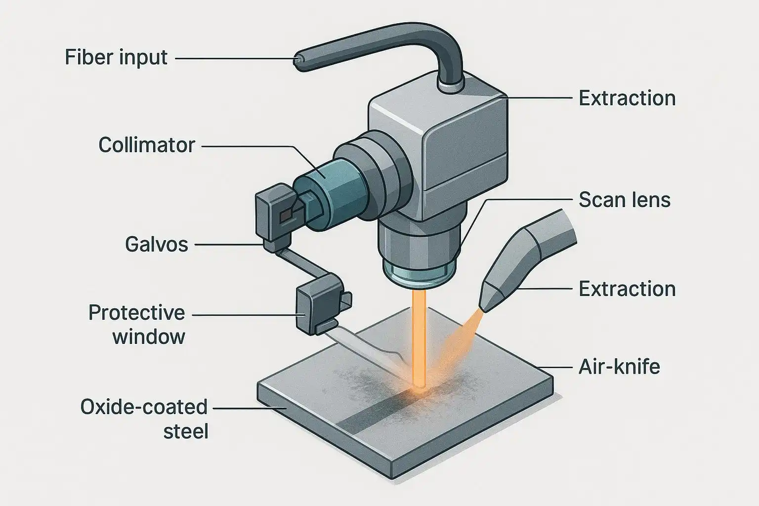
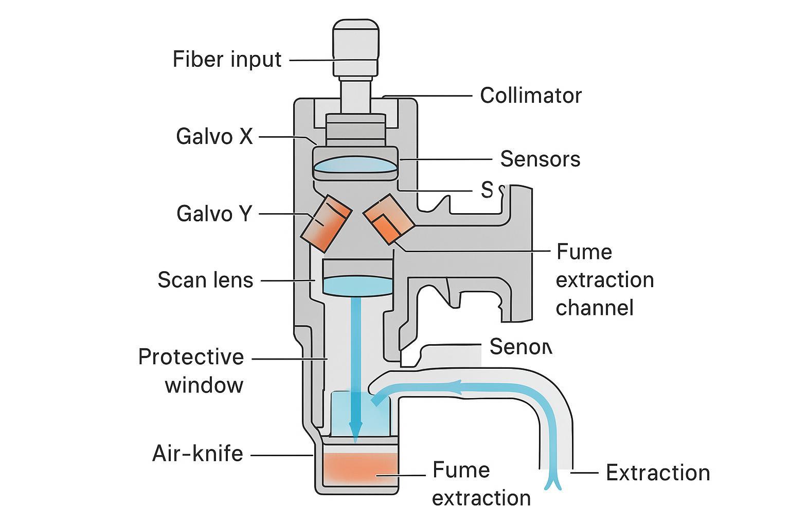
A laser cleaning head concentrates and steers pulsed light to remove oxides, paint, and residues while preserving the underlying substrate. Inside the head, each component—from fiber input and collimation to galvos, scan lens, protective window, and airflow—shapes spot size, fluence, scan field, speed, and cleaning uniformity. Get those elements right, and you’ll protect the base material and cut rework; get them wrong, and you risk uneven results, redeposition, or surface damage.
This guide assumes a nanosecond pulsed fiber source at ~1064 nm in the 100–500 W class and focuses on substrate safety and precision. It’s written for practitioner-level beginners—engineers, maintenance techs, and integrators—who need clear fundamentals, practical guardrails, and verification steps they can apply on day one.
How to use this guide: skim the anatomy, follow the safety-forward guardrails, then apply the checklists when selecting lenses, setting standoff, choosing a scan pattern, and maintaining optics and airflow. When we cite standards or technical notes, we link to authoritative sources so you can go deeper as needed.
Key takeaways
- Start conservative for substrate safety: prioritize good collimation and beam quality, keep focus stable, and verify with witness coupons before touching production parts.
- Use the central scan field, moderate overlaps, and smooth pattern transitions to avoid edge artifacts and local overheating.
- Choose lenses for the job: F-theta for larger fields and speed; telecentric when perpendicular incidence and edge uniformity matter most.
- Guard the optics: keep a clean, replaceable protective window; pair an air-knife with close-capture extraction and confirm capture with a smoke test.
- Make safety non-negotiable: apply Class 4 laser controls per IEC/ANSI standards, integrate interlocks, and use LEV with appropriate filtration.
Optical path basics
A laser cleaning head’s optical train defines what’s physically possible. Three fundamentals—collimation, beam quality, and standoff—set your spot size and fluence window.
Fiber input & collimation
A delivery fiber emits a diverging beam set by its numerical aperture (NA). The collimator converts that cone into a near-parallel beam sized to properly fill the scan lens. If the beam underfills the lens, you waste aperture and grow the focal spot; overfill or clip and you distort the beam and create hot edges.
Simple guardrails:
- Match collimator focal length to the fiber’s NA and core to achieve the desired output diameter with minimal residual divergence.
- Expand the beam only enough to fill (not clip) the scan lens’ clear aperture.
- Verify collimation with a target at two distances; the spot should change size minimally when the beam is well collimated.
For background on collimation, NA, and beam expansion principles, see the RP Photonics encyclopedia entries on the fundamentals of collimated beams and beam collimators (publisher reference).
Beam quality and fluence
Beam quality (often expressed as M²) determines how tightly you can focus. Worse M² inflates the focal spot, lowering fluence for a given pulse energy. As a starting method, estimate fluence F from pulse energy Ep and spot diameter d at focus:
F ≈ Ep / A, where A = π(d/2)²Begin with low fluence on a witness coupon; inspect for cleanliness without color change or texture growth in the substrate, then step up cautiously. For readable primers on M² and its impact on focus and fluence, consult RP Photonics’ entries on the M² factor and beam quality.
Alignment and standoff
Depth of focus is limited. A tighter spot cleans efficiently but is more sensitive to standoff error. The Rayleigh range zR for a Gaussian-like beam gives a sense of focus tolerance: zR = π·w0²/λ, where w0 is the waist radius and λ ≈ 1064 nm. Non-ideal beams (M² > 1) effectively shorten this range. In practice, lock standoff mechanically and verify on a calibration plate. A clear primer on Gaussian beam propagation and depth of focus is available from Edmund Optics in Gaussian Beam Propagation.
Beam steering with galvos
Inside the head, two galvanometer mirrors (X and Y) steer the collimated beam through the scan lens. Their motion determines path shape, coverage, and thermal history.
Scan patterns and overlap
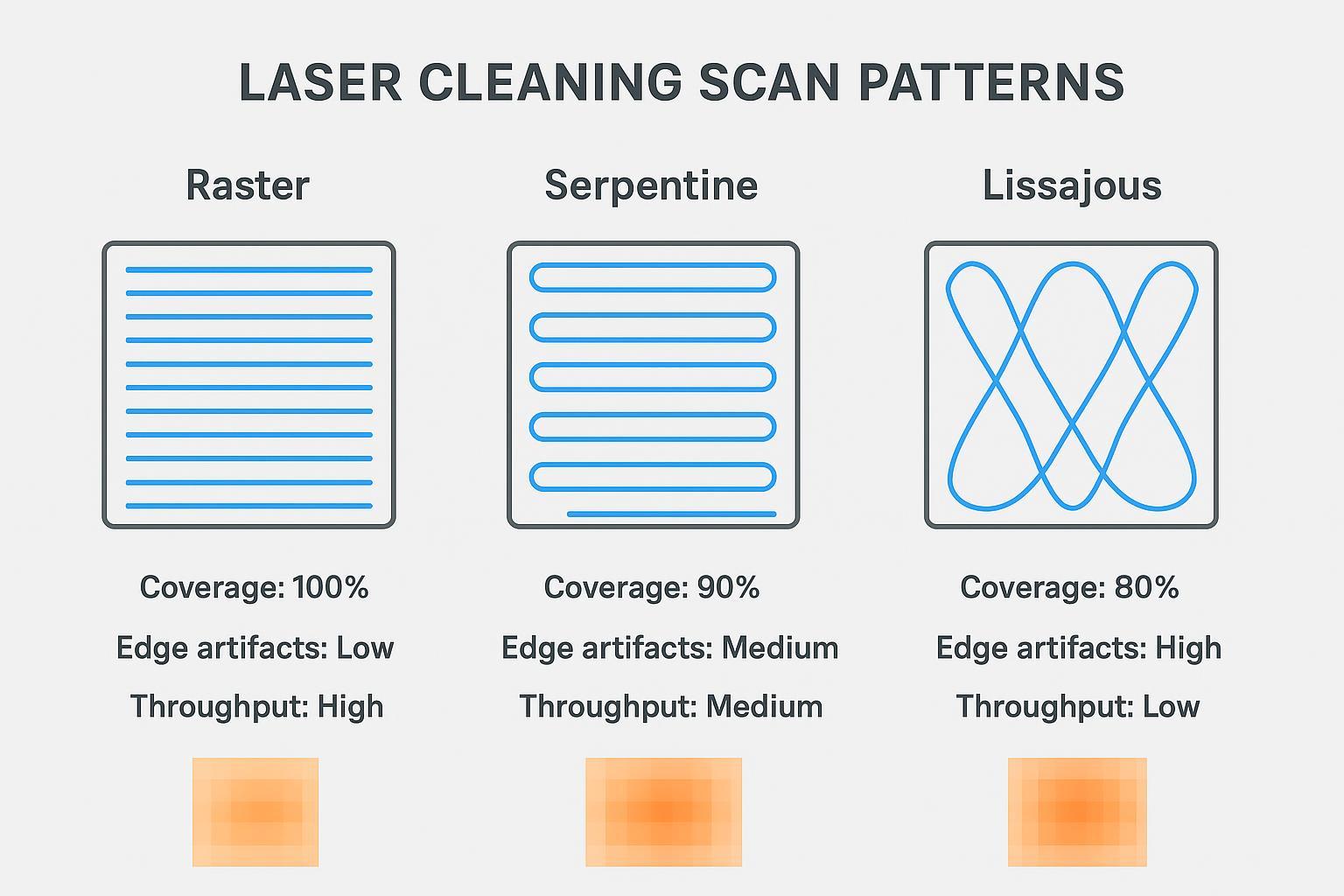
Raster (line-by-line) is straightforward but can produce thermal banding if turnarounds spike dwell; serpentine (a continuous zigzag) trims dead time and often stabilizes temperature; Lissajous (sinusoidal X/Y) can deliver dense coverage on complex shapes, though it demands careful tuning for even dwell. A cross-domain review in Optical Engineering surveys how scan strategies influence uniformity in laser-based additive manufacturing; the coverage principles carry over with care to cleaning.
Begin with moderate overlap (e.g., 20–40% as a conservative starting band), then tune by microscopy and cleanliness checks.
Field size and edge effects
Scan lenses map mirror angle to a planar field. The most uniform spot geometry and energy density typically live in the central region. Toward the edges, incidence angle changes and field curvature can shift spot shape and fluence. Keep critical work in the central 60–70% when uniformity is paramount, add small over-scan margins so mirrors reverse off-part, and consider telecentric optics for thin coatings or delicate substrates where perpendicular incidence helps.
Accuracy, jitter, and speed
Mirror dynamics set how accurately the beam follows the commanded path. As speed and field angle rise, tracking error, jitter, and nonlinearity increase. Use acceleration limits and smoothing to protect corners and minimize dwell spikes. Leading scan-head makers publish repeatability and step-response data showing how errors grow with speed; use those relationships to shape motion profiles even if your exact hardware differs.
Focusing optics
The scan lens shapes the field and incidence angles; pairing and setup directly influence uniformity and safety.
F-theta vs telecentric
An F-theta lens maps angle to position linearly across a flat field and is the workhorse for cleaning larger areas efficiently. A telecentric F-theta lens adds near-perpendicular incidence across the field, improving edge uniformity and spot geometry—useful when even fluence at boundaries is critical. For deeper reading, consult Sill Optics’ technical guide to F-theta lenses and Edmund Optics’ primer on the advantages of telecentricity.
Spot size and depth of focus
Trade-off basics:
- Smaller spot → higher peak fluence but shallower depth of focus; sensitive to standoff.
- Larger spot → lower peak fluence but more forgiving focus.
Worked example (order-of-magnitude): if pulse energy Ep = 1 mJ and the focal spot diameter d ≈ 200 µm, spot area A ≈ π(0.1 mm)² ≈ 0.0314 mm², so F ≈ 1 mJ / 0.0314 mm² ≈ 31.8 mJ/mm². Use this only as a comparative gauge; confirm efficacy and substrate safety on coupons before production.
Working distance and field flatness
Choose focal length to balance clearance for air-knife and extraction with tolerable standoff sensitivity. Longer focal lengths generally increase working distance and depth of focus but can enlarge the spot and reduce available fluence. Manufacturers discuss working distance and field flatness in their F-theta documentation; these concepts are consistent across industrial scan optics.
Protection and sensing in the laser cleaning head
Protecting the optics and verifying standoff are make-or-break for consistent, safe cleaning.
Protective window care
Use a removable protective window to catch plume and spatter. Before each shift, inspect under bright, angled light. If you must clean, follow optics SOPs: blow off loose debris with clean, dry air or nitrogen; then, only if needed, drag-wipe with reagent-grade IPA or acetone on lint-free tissue. Replace the window if haze or pitting persists or if transmission loss is evident in your process camera. Detailed guidance is available from LASER COMPONENTS’ expert tip How to Clean Laser Optics and Edmund Optics’ FAQ How do I clean my optics?.
Air-knife and extraction
Pair the air-knife with local exhaust ventilation (LEV). Aim the jet to sweep particulates away from the protective window and toward the capture nozzle. Place the hood close—ideally within about one nozzle diameter—and slightly downstream of the plume. Verify capture with a smoke test at your typical process setpoints. OSHA’s Technical Manual chapter on local exhaust ventilation outlines near-source capture principles used across industries; their laser hazards standards page summarizes how IEC/ANSI frameworks apply in workplaces.
Sensors, vision, and control
Lock standoff mechanically and verify automatically. Common sensing methods include laser triangulation (fast, micron-class over short ranges), confocal displacement (very high resolution, robust on varying reflectance), and time-of-flight (longer range, lower precision). For accessible primers, see Keyence’s overview of non-contact displacement methods and application notes on gauge-style measurements.
Cooling and safety
Thermal stability and safety controls protect both the process and the people.
Thermal management
Galvo mirrors, control electronics, and some optics are temperature sensitive. Confirm coolant temperature and flow before operation, allow warm-up to stabilize drift, and monitor temperatures where sensors are available. Industrial scan-head datasheets typically specify operating ranges and drift coefficients (e.g., µrad/K); treat those as hard limits when setting interlocks.
Interlocks and standards
Treat the assembly as a Class 4 laser system and implement engineering and administrative controls per recognized standards. IEC 60825-1 defines laser product classes and core safety requirements, and ANSI Z136.1 (with Z136.9 for manufacturing) details hazard evaluation, eyewear selection, and the role of the Laser Safety Officer. A concise 2022 summary of Z136.1 is provided by ANSI’s overview Safe Use of Lasers; OSHA’s laser hazards page links the broader framework back to workplaces.
Fume control and PPE
Laser-generated air contaminants (LGAC) from oxide/paint removal demand close-source capture and proper filtration. Use LEV with HEPA filtration (and activated carbon if organics are present), confirm capture visually, and maintain filters per manufacturer guidance. Select eyewear with optical density matched to ~1064 nm and your process parameters as directed in ANSI Z136.1. OSHA’s OTM sections on ventilation reinforce near-source capture as a primary control strategy.
Conclusion
Design choices inside the laser cleaning head directly set consistency, cycle time, and—most importantly—substrate safety. Prioritize clean collimation and good beam quality, select lenses that keep incidence appropriate across the field, steer with patterns that avoid dwell spikes, and protect/verify standoff while keeping optics clean. Support it all with stable cooling, rigorous interlocks, and effective LEV and PPE.
Next steps: on a test coupon, calculate an initial fluence, pick a conservative overlap and a serpentine or well-tuned raster pattern, lock focus with a gauge or sensor, and validate cleanliness without base damage under magnification. Document the recipe, then scale to production—staying in the central field and maintaining the protective window and extraction as part of your daily routine.


