Introduction
Finding the true fusion line in a laser weld isn’t academic—it determines whether a joint really met its procedure, whether a failure initiated in fusion or heat-affected material, and whether corrective actions are targeted or guesswork. In laser welds, the narrow HAZ, steep thermal gradients, and keyhole pool geometry can make boundaries subtle. Corrosion metallography, executed with a consistent preparation chain and alloy-appropriate etching, is still the fastest route to a reliable boundary—provided we verify chemically and not just by contrast.
This guide walks through a standards-aligned workflow: prepare the specimen according to best practice, apply alloy-specific etchants, and confirm the boundary using a primary EDS/EPMA line-scan method supported by macroetch correlation and a microhardness traverse. We align terminology and reporting with ISO 17639 and adopt preparation/etching practices summarized in ASTM E3 and ASTM E407 so the results are reproducible and audit-ready.
Key takeaways
- The laser weld fusion line is best confirmed by chemistry: an EDS/EPMA line scan that shows coincident inflection points of dilution-sensitive elements at the boundary.
- Use macroetch correlation (profile/penetration) and a microhardness traverse as supporting methods to triangulate the location and assess zone widths.
- For austenitic stainless steels and nickel-based superalloys, meticulous prep to 0.05 μm and conservative, freshly mixed etches are critical to avoid relief and false boundaries.
- Document orientation, etchant, magnification, and acquisition parameters; create plots and image metadata so results are defensible in audits.
- Safety first: many etchants are hazardous; work in a hood with the correct PPE and follow SDS and lab safety standards.
Standards and definitions
What the fusion line is
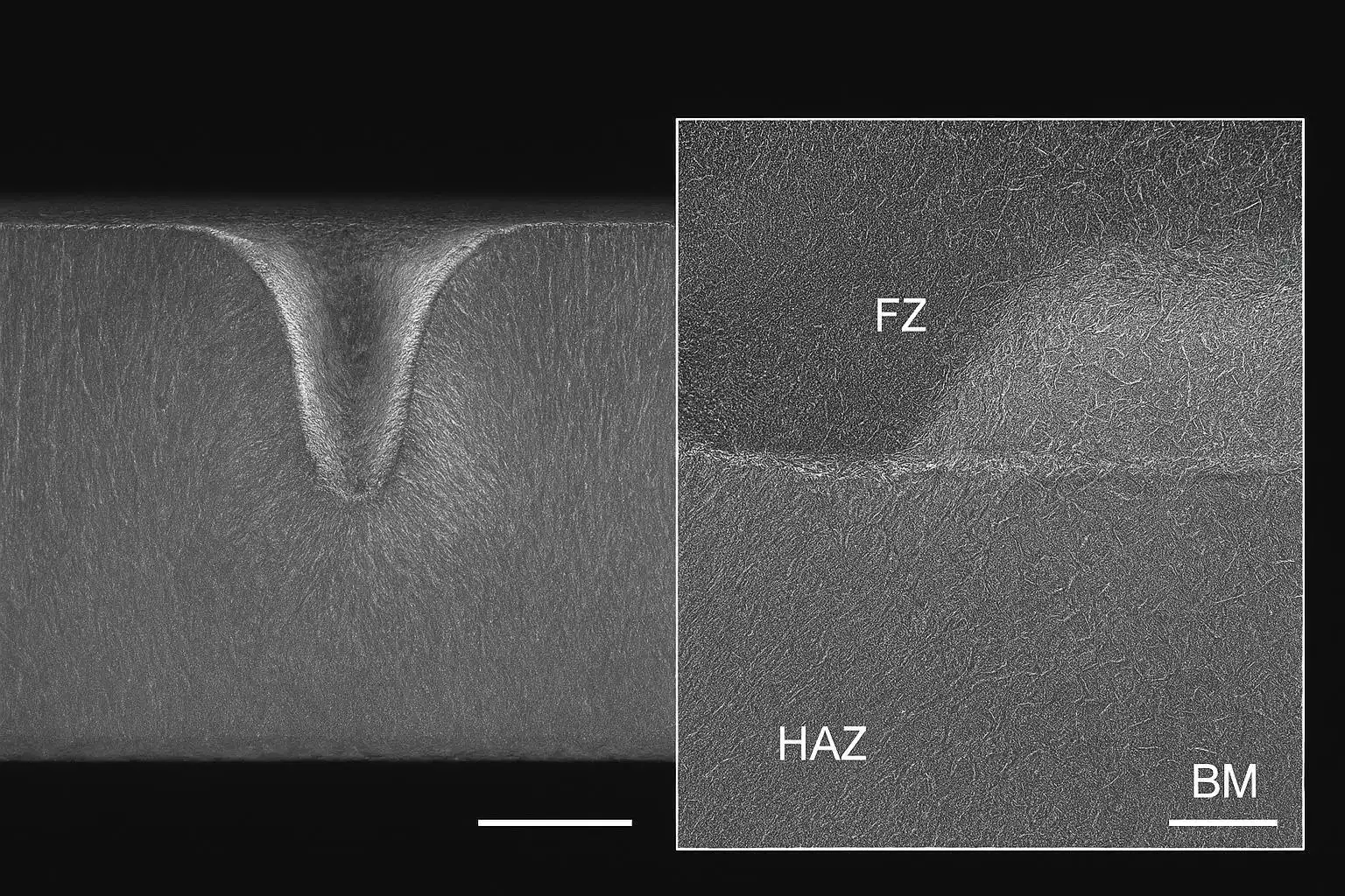
The fusion line is the metallurgical boundary where base metal has just melted and mixed with weld metal; on the fusion-zone side you’ll see cast dendritic solidification, while on the HAZ side the base metal is solid-state transformed only. In laser welds, this boundary is often sharp and follows the keyhole pool contour. Macroscopically it tracks the fusion face; microscopically it appears where cast morphology yields to worked/base microstructure and where composition begins changing due to dilution.
Where macro vs. micro fit per ISO 17639
ISO 17639 distinguishes macroscopic examination (typically up to ×50) from microscopic examination (around ×50–×500) and prescribes how to designate and report each. Use macro to establish weld geometry, penetration, and likely boundary zones, then zoom in for micro confirmation and documentation. See the scope and reporting recommendations in the 2022 edition overview from the standards body in According to the publisher’s summary in the EN ISO 17639:2022 overview, macroscopic and microscopic examinations require clear reporting of section orientation, magnification, and etchant details to ensure traceability across labs. For an authoritative synopsis, consult the publisher page for the 2022 revision and the official overview of macroscopic/microscopic practices.
Key clauses from ASTM E3/E407
ASTM E3 outlines the preparation chain—controlled sectioning, mounting, grinding, polishing, and cleaning—to deliver a flat, scratch-free surface with minimal deformation so chemical etching reflects real structure. ASTM E407 compiles microetch reagents and electrolytic procedures by alloy system and purpose (grain boundaries, phases, general structure). For procedural context and reagent selection, see the standard pages and respected handbooks summarizing them, such as the publisher’s guide to ASTM E3 and the etching compendium in ASTM E407 as summarized in metallography references. Authoritative handbooks like the ASM Metallography and Microstructures volume also tabulate widely used recipes and application cautions for stainless steels and nickel-based superalloys.
Specimen preparation workflow
Sectioning and mounting essentials
- Section transverse to the weld axis to include full bead, HAZ, and adjacent base metal. Use a low-deformation cut with coolant to avoid rehardening or tinting that could bias etch response.
- Maintain heat control; dress wheels frequently; avoid smearing at the weld toe. For thin lap joints (austenitic stainless), support the free edge to preserve planarity for indents and line scans.
- Mount in thermoset or low-shrink epoxy with the weld centered and a reference edge square to the section plane. Label the orientation and ID to match the welding procedure record.
Industry guides in metallographic preparation emphasize minimizing mechanical damage and ensuring a uniform surface before etching and imaging, a principle echoed in the publisher’s page for ASTM E3 and lab-method summaries from accredited providers.
Grinding and polishing to 0.05 μm
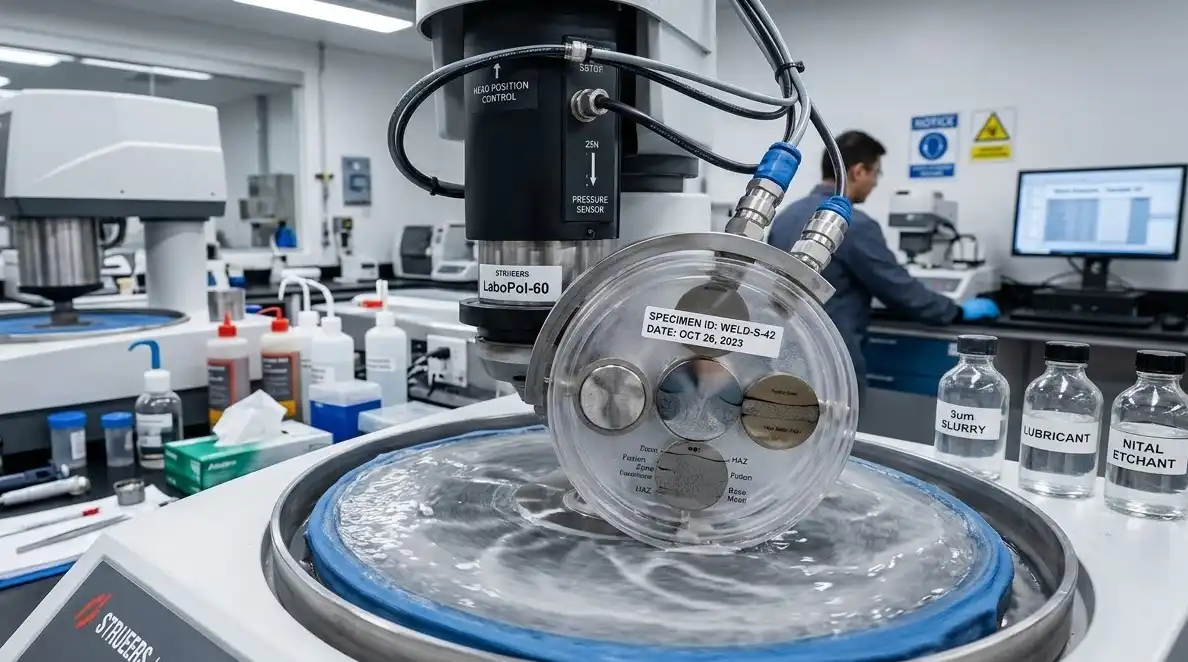
- Abrasive schedule (typical): SiC P240 → P400 → P800 → P1200 → P2400 → P4000. Rinse thoroughly between steps.
- Diamond polishing: 9 μm → 3 μm → 1 μm on appropriate pads; keep loads modest to avoid relief at the fusion boundary.
- Final polish: 0.05 μm colloidal silica (short mechanical or vibratory) to remove the last deformation and reduce topography that can create false contrast. Rinse/ultrasonic clean and dry.
Application notes for welding metallography and stainless steel preparation show that polishing to 0.05 μm significantly reduces relief and improves boundary readability without over-etching; see consolidated recommendations in Buehler’s welding metallography note and Struers’ stainless knowledge pages.
Surface cleaning before etching
Before etching, remove heat tint, oxide films, and residues that can disrupt uniform chemical attack.
A neutral, instrumented approach is to introduce a controlled pulsed-fiber laser cleaning pass to strip oxides without altering the base metal, followed by solvent and, if needed, ultrasonic cleaning. For example, an industrial 1064 nm fiber source configured for low-thermal fluence with tightly bounded recipes—power in the low hundreds of watts, pulse frequency in the tens to low hundreds of kHz, spot size on the order of tens of micrometers, and scan speeds in the hundreds of mm/s—can be validated for metallographic cleanliness. Using equipment from Oceanplayer, a lab could document:
- ΔRa roughness change on a mirror-polished coupon (target ≤0.02–0.05 μm delta measured by a surface profilometer),
- Oxide removal efficacy via XPS or controlled mass-loss on oxide-coated test coupons, and
- A heat-input threshold showing no hardness shift and no tinting beyond the treated lane.
These evidence points ensure the cleaning step supports, rather than biases, the etch. Conclude with reagent-grade alcohol rinse and an ultrasonic dip to lift loosened debris. Note: parameters are material- and optics-dependent and should be qualified on sacrificial specimens.
Alloy-specific etching to reveal the boundary
Carbon and low-alloy steels
Although this guide focuses on austenitic stainless and nickel-based superalloys, carbon/low-alloy steels often appear in mixed-production labs. Common approaches include Nital (2–5% nitric in ethanol) for general structure and picral variants for carbide delineation. For macroetch, hydrochloric-based solutions per macro standards can reveal bead profiles quickly. Refer to widely used compendia of etchants for compositions and time ranges and align macro practice with recognized macroetch standards for destructive examination of steel welds.
Stainless steels (austenitic, ferritic/martensitic)
For austenitic stainless steels (e.g., 304L/316L thin-sheet lap or tube-to-plate joints):
- Electrolytic oxalic acid around 10% (aq) at roughly 6 V for about 30–90 s is widely used to delineate grain boundaries and sensitization features. Apply with a stainless cathode, maintain contact, and watch under the scope to avoid pitting. See guidance compiled from stainless etching authorities and microetching standards summaries.
- If general contrast is low, swab etches such as Kalling’s No. 2 or freshly prepared glyceregia (glycerol–HCl–HNO₃) can bring out FZ dendrites and boundary transitions. Mix nitric-containing reagents fresh and never store.
- For delta-ferrite detection in austenitic weld metal, selective etches (e.g., persulfate variants) or tint/color etches can aid confirmation; corroborate with phase-prediction tools and microanalysis.
Ferritic/martensitic grades respond to different chemistries (e.g., Vilella’s for tempered martensite). Always re-polish if relief or intergranular attack appears, then re-etch gently.
Authoritative practice and recipes are summarized in stainless etching notes by recognized experts and in the microetching standard’s tables.
Aluminum and nickel alloys
Nickel-based superalloys (e.g., Alloy 625, Inconel 718) demand cautious, short, observed etches:
- Glyceregia (e.g., 3 HCl : 2 glycerol : 1 HNO₃; freshly mixed; short swab, seconds to a minute) often reveals γ/γ′ distributions and fusion-boundary contrast with minimal pitting when observed closely.
- Marble’s reagent (water + HCl + CuSO₄) can define grain outlines and dendrites; waterless Kalling (ethanol + HCl + CuCl₂) may enhance boundary contrast.
- Aging condition controls etch response; aged IN718 tends to etch faster. Keep sessions brief and rinse/neutralize immediately.
For aluminum, Keller’s or Barker’s electrolytic etch is common, but because this guide centers on austenitic stainless and Ni-based superalloys, treat aluminum as context and follow aluminum-specific procedures when needed. Practical recipes and cautions are compiled in superalloy metallography guides from recognized metallographic authorities and specialty alloy producers.
Verification of the true boundary
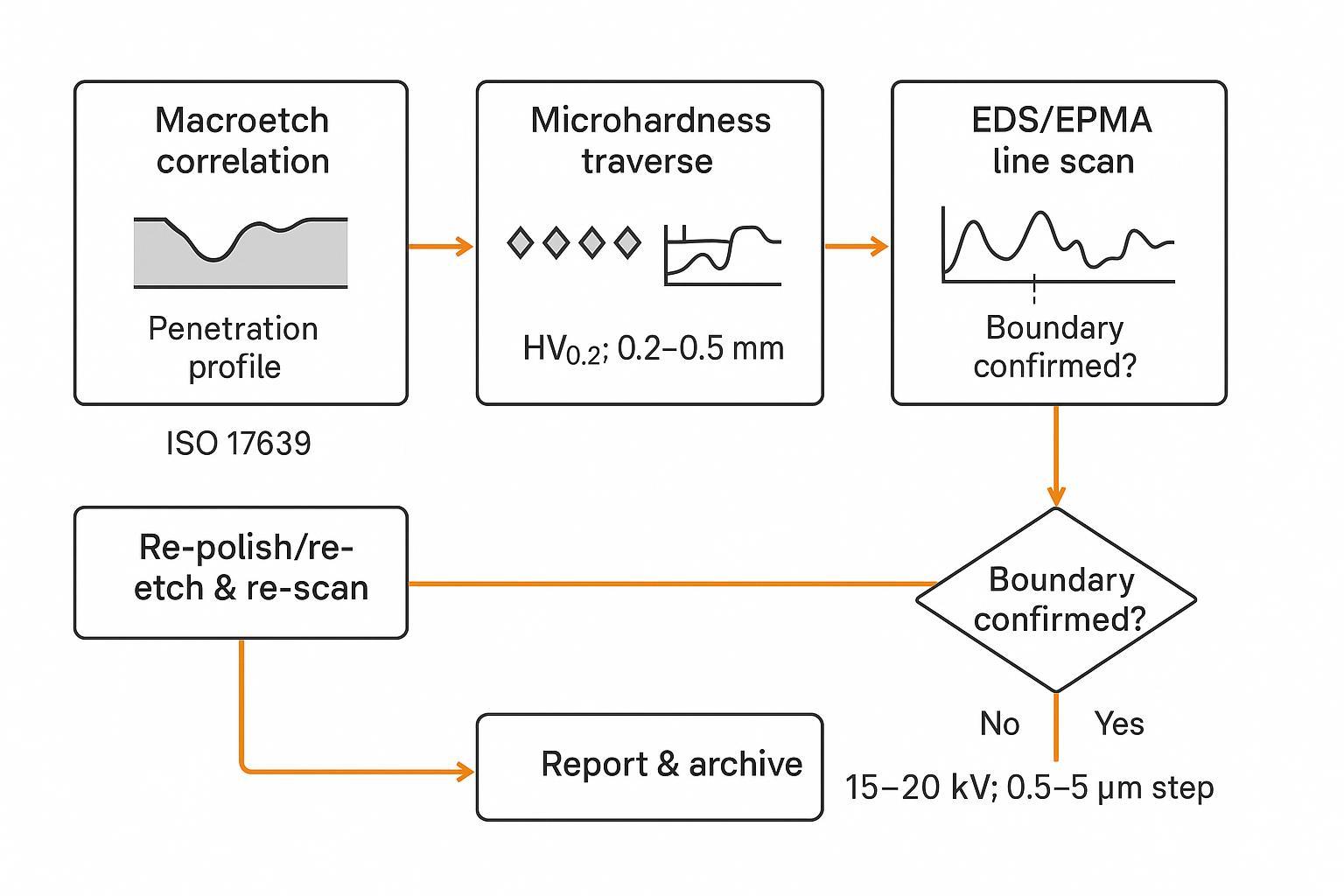
Macroetch correlation of weld profile
Start with a macroetched transverse section that cleanly shows the bead silhouette and penetration. The macro profile establishes context for where the fusion face should lie and whether the expected keyhole geometry formed. Record magnification, etchant, and location per the destructive examination standard. Macro images are not sufficient to declare the boundary in laser welds—but they help you place microfields correctly and avoid chasing artifacts. For macroetch practices and reporting expectations, see the guidance embedded in ISO 17639 overviews and the macroetch method standard used widely for metallic materials.
Microhardness traverse across FZ/HAZ/BM
Run a Vickers microhardness traverse orthogonal to the presumed boundary to profile FZ→HAZ→BM. A pragmatic setup for laser welds uses HV0.2 (≈200 gf), 0.2–0.5 mm spacing, and at least ten indents spanning both sides of the boundary. Maintain spacing of ≥2.5–3 times the indent diagonal to limit interaction. Report mean and standard deviation by zone and overlay hardness on the macro/micro images. While microhardness doesn’t locate the laser weld fusion line by itself, it corroborates zone widths and reveals overtempering or rehardening. Foundational method details and reporting conventions are described in the Vickers hardness standards overviews and vendor method notes.
EDS/EPMA line scans and decision rules
Primary confirmation relies on chemistry. Acquire a line scan normal to the suspected boundary using SEM-EDS or EPMA (WDS preferred for low-level precision). Typical acquisition settings for Fe–Cr–Ni steels and Ni-based superalloys:
- 15–20 kV acceleration voltage (optimize for target lines and limit interaction volume as required),
- 0.5–5 μm step size for optical fields; narrow HAZ cases may need sub-micrometer steps with EPMA/STEM-EDS,
- Dwell sufficient to achieve stable counts (for EDS, target >10k counts per peak; for EPMA, set beam current/dwell to meet <5% relative error), using matrix corrections (ZAF/PAP) and standards when quantifying.
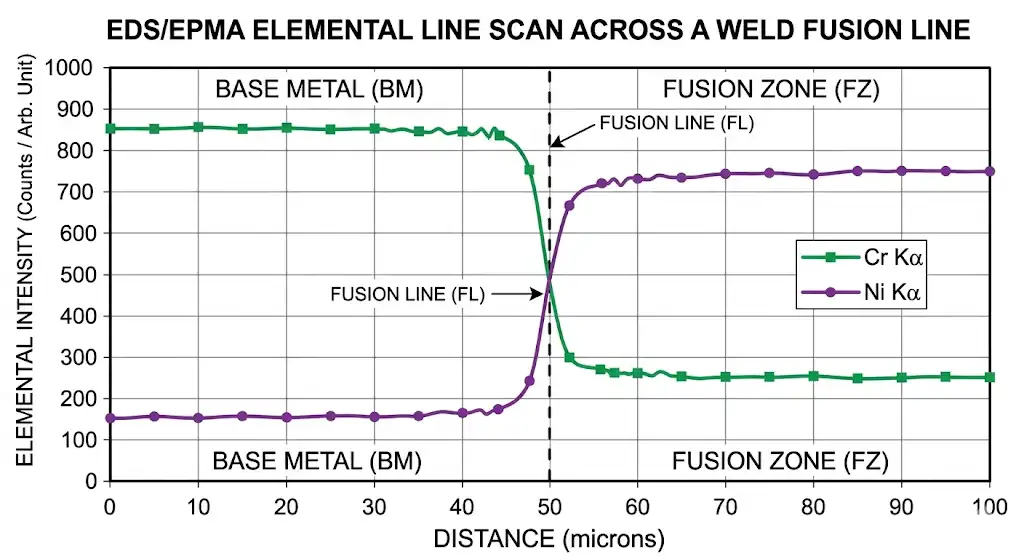
Decision rules for the true boundary:
- Identify the boundary at the location of maximum slope (first-derivative peak) for at least two dilution-sensitive elements that change in opposite or differing magnitudes across BM→FZ.
- Austenitic stainless steels: prioritize Cr, Ni, and Mo profiles; expect a break where FZ dilution begins relative to BM composition.
- Nickel-based superalloys: prioritize Al, Ti, Nb and track Cr/Mo; inflections at the fusion boundary often accompany precipitate distribution changes.
- Confirm the pick against microstructural cues (dendritic-to-wrought transition) and against macro geometry (pool contour).
- If the derivative peak is broad due to interaction volume, repeat at lower kV or finer step size, or use EPMA/WDS for higher spatial fidelity.
- For autogenous laser welds, check for symmetry about the centerline; with filler, anticipate asymmetry and align the scan accordingly.
Authoritative handbooks and standards-aligned overviews provide acquisition and interpretation practices for weld microanalysis; use them to build an auditable method description and specify your instrument parameters with each report.
Pitfalls and troubleshooting
Over-etching and polishing relief artifacts
Excess etch time or aggressive cloths can create relief, making ledges and shadows that mimic boundaries. If you see topography under oblique light, re-polish at 1 μm and 0.05 μm, shorten the etch, and observe under the scope during application. Maintain clean lubricants and pads; replace slurries frequently to avoid embedded grit.
PMZ and liquation bands vs. the fusion line
Partially melted zones and liquation bands can run parallel to the boundary on the HAZ side, especially in Ni-based superalloys, and be misread as the fusion line. Look for continuity of dendrites on the weld-metal side and verify chemistry: PMZs won’t show the same compositional break as the true boundary. If doubt remains, add a second EDS line parallel and a few tens of micrometers away to check for consistent inflection behavior.
Intergranular attack and heat tint misreads
Heat tint is an oxide color and must be removed before etching or it will disrupt attack and mislead at low magnification. Intergranular attack from strong etches or sensitized stainless can carve paths that resemble a boundary. Use conservative, freshly mixed reagents; rinse and neutralize immediately; and confirm with EDS/EPMA where the composition actually changes.
Documentation, safety, and reporting
Recording parameters and images
Adopt an image metadata template so every macro and micrograph records: section orientation and location, etchant and application (composition, method, time, temperature/voltage), surface finish, magnification, scale bar length, and date. Include hardness traverse parameters (load, spacing, dwell) and EDS/EPMA acquisition settings (kV, probe current, dwell, step size, detector). ISO 17639 overviews emphasize this level of documentation so examinations are traceable and repeatable across projects and auditors.
Etchant handling and lab safety
Work in a fume hood with chemical-resistant gloves, goggles/face shield, and a lab coat or apron. Add acid to water, never the reverse. Prepare nitric-containing mixes like glyceregia fresh and never store them; segregate incompatible wastes and label containers. Where historical recipes used hexavalent chromium, choose safer alternatives when possible and follow disposal regulations. For lab safety frameworks and SDS-driven practices in metallography, consult the lab safety guide for metallography and manufacturer safety notes that summarize personal protection, mixing order, and neutralization.
Presenting results for audits
Build an audit pack that a third party could replicate:
- Macro images (etched and, if helpful, unetched) with weld geometry annotations (penetration depth, bead width, probable fusion face),
- Micrographs at multiple magnifications showing the boundary area with etchant details in the captions,
- Hardness traverse plots labeled HV vs. distance with the load/spacing noted,
- EDS/EPMA line-scan plots with element profiles, boundary pick (derivative peak), and acquisition parameters,
- A short narrative that cross-references the welding procedure record and lists any deviations.
Store raw images and spectra alongside processed figures, and archive the etchant log and SDS references with the report.
Conclusion
The fastest way to a defensible answer on the true boundary in a laser weld is a disciplined, standard-aligned workflow: polish to 0.05 μm, etch with alloy-appropriate reagents, and confirm the laser weld fusion line with an EDS/EPMA line scan that shows coincident inflection points in dilution-sensitive elements. Use macroetch and microhardness to frame the story and quantify zone widths, but let chemistry settle the boundary. Careful documentation, safety-first handling of reagents, and complete reporting make the result replicable and audit-ready, reducing misreads from relief, PMZ, or heat tint and improving consistency across teams.
References (selected, descriptive links):
- According to the EN ISO 17639:2022 overview on macroscopic/microscopic examinations and reporting: https://weldcalc.ssab.com/sisStandards/ISO%2017639.pdf
- See the publisher’s page for ASTM E3 guidance on specimen preparation: https://www.astm.org/e0003-11r17.html
- For microetch reagents and application notes summarized from ASTM E407 and handbooks: https://www.metallographic.com/Metallographic-Etchants/Metallography-Stainless-steel-etchants.html
- Practical welding metallography tips and prep schedules (Buehler technical note): https://www.buehler.com/assets/solutions/technotes/Welding-Metallography-Ferrous-Metals-TechNote-Volume-4-Issue-3.pdf
- Superalloy metallography overview with etching cautions (Vander Voort): https://vacaero.com/information-resources/metallography-with-george-vander-voort/880-metallography-of-superalloys.html
- Vickers microhardness method context and best practices (Struers knowledge page): https://webshop.struers.com/en/knowledge/hardness-testing/vickers/


