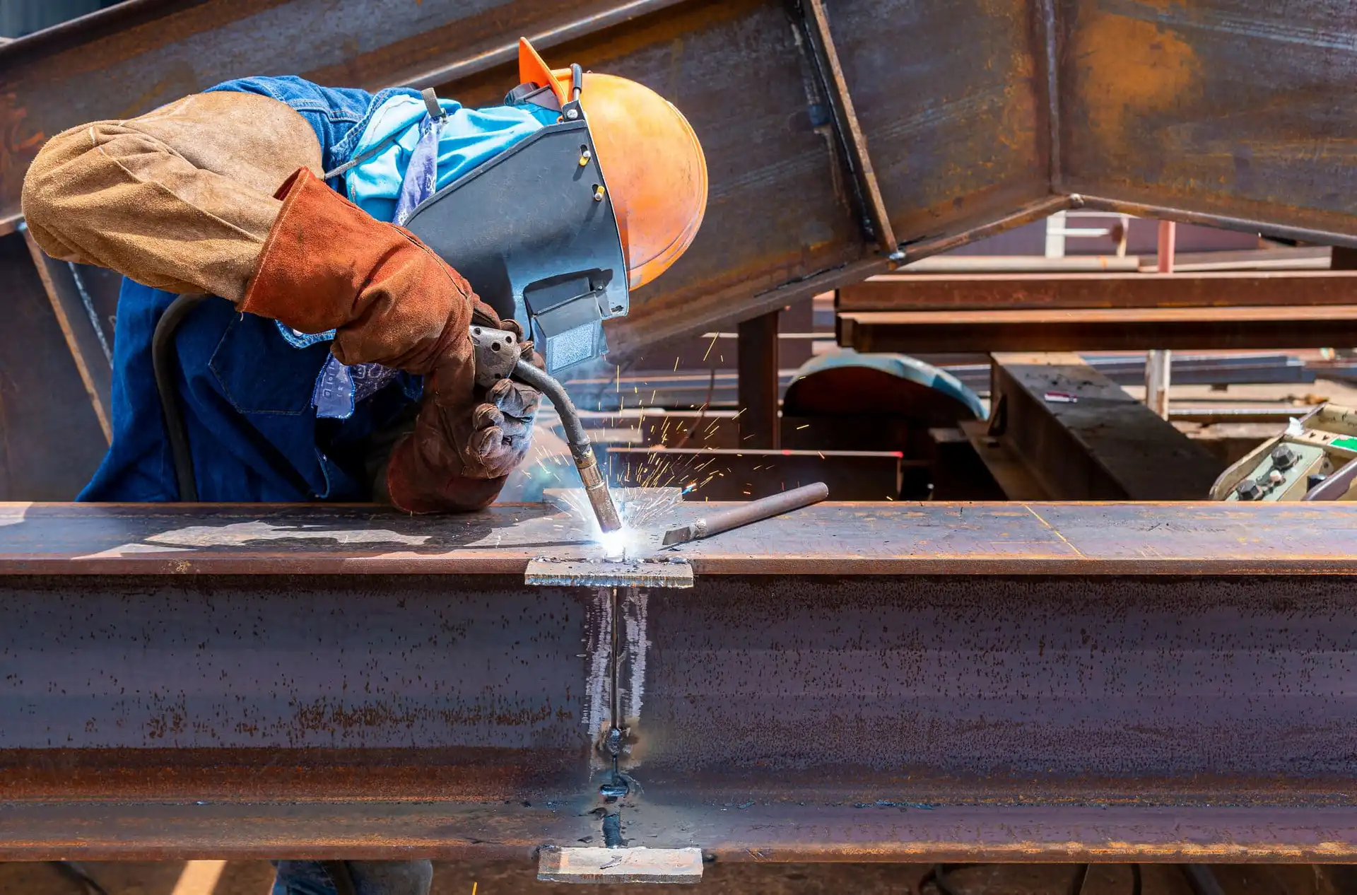
Flux core welding—formally Flux-Cored Arc Welding (FCAW)—is an arc welding process that uses a continuously fed, tubular wire filled with flux. The flux creates protective gases and slag around the molten pool, shielding it from the atmosphere. Depending on the wire, the process can be self-shielded (no external gas) or paired with an external shielding gas.
In technical terms, FCAW uses a consumable flux-cored electrode and typically a constant-voltage (CV) power source. Shielding arises from flux decomposition alone (FCAW-S) or from flux plus externally supplied gas (FCAW-G). The flux also forms a slag that protects the solidifying weld metal and must be removed between passes.
Key takeaways
- Flux core welding uses a tubular, flux-filled wire; shielding can be self-generated (FCAW-S) or supplemented by external gas (FCAW-G), as described by the American Welding Society in its overview of FCAW principles and applications.
- Typical polarity: many gas-shielded wires run DCEP; some self-shielded wires require DCEN—always confirm the wire data sheet and your WPS before striking an arc.
- For FCAW-G, CO₂ maximizes penetration but tends to create more spatter; Ar/CO₂ blends usually reduce spatter and improve bead appearance, enabling faster travel in many cases.
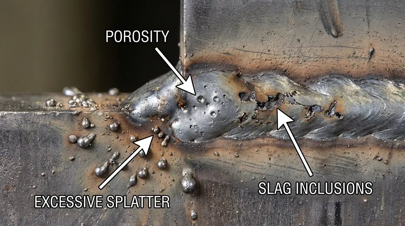
- Primary quality risk and cost driver: slag inclusions, porosity, and spatter. Control cleaning between passes, stickout, angle, voltage/wire-feed balance, and (for FCAW-G) gas flow.
- Safety matters: local exhaust ventilation (LEV), fume capture near the arc, and monitoring for manganese exposure per NIOSH/OSHA guidance.
What flux core welding is and how it works
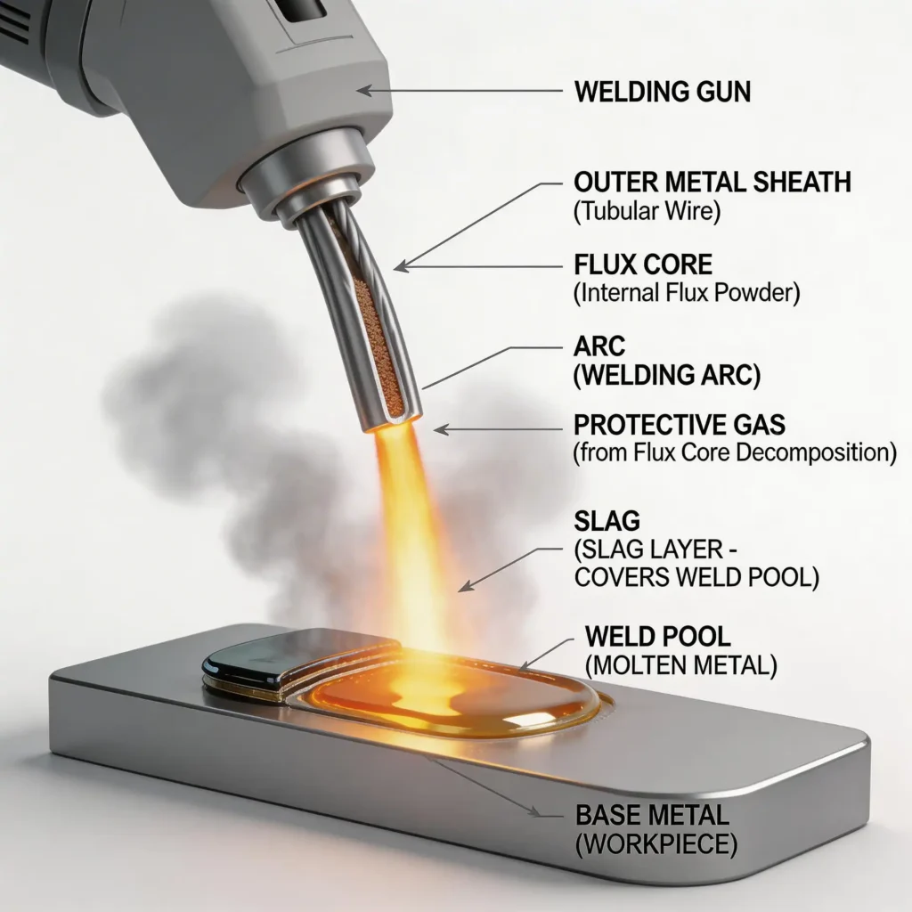
Think of the flux in the wire as a built-in, time-release shield. As the arc heats the tubular electrode, the flux decomposes, generating shielding gases that displace air, while forming a slag layer that covers and protects the hot weld metal as it solidifies. With FCAW-S, this flux-generated shielding is all you need. With FCAW-G, you add external gas—commonly CO₂ or an Ar/CO₂ blend—to further stabilize the arc and tune penetration and bead profile.
Most FCAW is run on a constant-voltage power source with a wire feeder. “Electrical stickout” (the distance from the contact tip to the arc) is an important control: self-shielded wires often use longer stickout than gas-shielded wires. Stickout affects current density and heat input, which in turn influences fusion, spatter, and the likelihood of defects like porosity or undercut.
Authoritative primers summarize these mechanics and trade-offs. For a concise engineering overview of the process, see the American Welding Society’s 2025 coverage of FCAW principles, uses, and common challenges.
FCAW-S vs FCAW-G
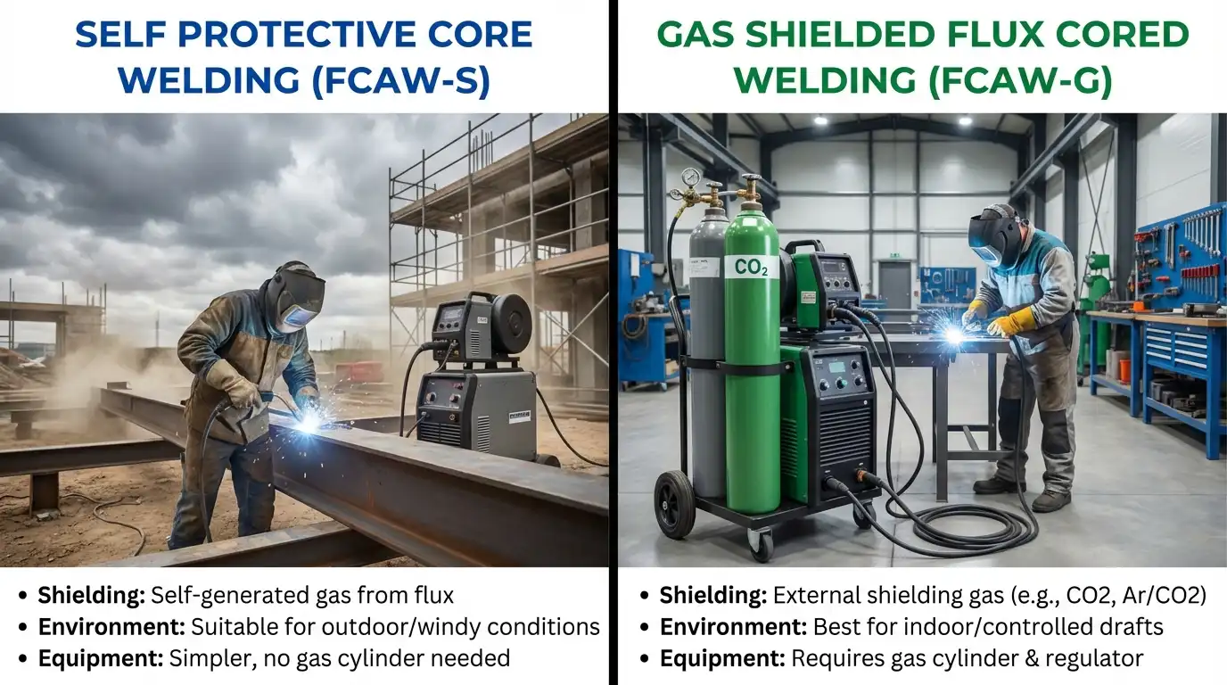
Self-shielded (FCAW-S) and gas-shielded (FCAW-G, sometimes called “dual-shield”) behave differently in practice. FCAW-S excels outdoors and on windy jobsites where gas shielding would be blown away. FCAW-G shines in controlled shop environments, often producing smoother beads and less spatter when paired with the right gas mixture.
| Aspect | FCAW-S (self-shielded) | FCAW-G (gas-shielded) |
|---|---|---|
| Shielding | Flux alone; no external gas | Flux plus external gas (CO₂ or Ar/CO₂) |
| Typical environment | Field work, windy/outdoor conditions | Shops and controlled environments |
| Cleanup | Slag removal required; spatter can be higher | Slag removal still required; generally cleaner bead and lower spatter with blends |
| Typical polarity | DCEP or DCEN—check the wire datasheet/WPS | Usually DCEP—check the wire datasheet/WPS |
| Finish | Functional, robust penetration | Often smoother appearance and more consistent arc |
According to the American Welding Society’s 2025 overviews of FCAW, this split in shielding approach explains why FCAW remains a mainstay both in field construction and heavy fabrication.
Polarity and shielding gases (what to use and why)
Polarity choices influence penetration, arc force, droplet transfer, and spatter. Many gas-shielded flux-cored wires are designed for DCEP (electrode positive). Some self-shielded wires are also DCEP, while others require DCEN (electrode negative). Here’s the deal: the correct polarity is whatever the wire manufacturer and your WPS say it is. Using the wrong polarity can spike spatter, cause lack of fusion, or create erratic arcs. An engineering note from ESAB underscores that certain self-shielded wires specifically require DCEN and urges verification against the datasheet and machine setup.
Shielding gas only applies to FCAW-G. Gas choice alters bead shape, spatter level, and travel speed headroom:
- 100% CO₂ is economical and delivers robust penetration but can increase spatter and cleanup.
- Ar/CO₂ blends (e.g., 75/25 or 90/10) typically yield a steadier arc, reduced spatter, and cleaner bead appearance; certain blends can also support higher travel speeds. Miller’s gas selection guidance for wire processes documents these trade-offs.
| Item | Typical option | Why it matters |
|---|---|---|
| Polarity (FCAW-S) | DCEP or DCEN (verify) | Flux chemistry dictates arc behavior and penetration profile |
| Polarity (FCAW-G) | DCEP (common) | Stable arc and appropriate metal transfer per wire design |
| Shielding gas | CO₂ or Ar/CO₂ blends | CO₂ = deeper penetration/rougher arc; blends = lower spatter/smoother bead |
Starting parameters you can build on
Always start from your wire manufacturer’s datasheet and the governing WPS. The entries below are representative values from accessible, authoritative datasheets—use them as directional starting points, then tune with test coupons.
| Wire and context | Voltage | Wire feed speed | ESO/Stickout | Gas flow |
|---|---|---|---|---|
| Self-shielded FCAW, 0.035 in, flat/horiz (example: Lincoln NR‑211‑MP) | ~16–22 V | ~175–700 ipm | ~1–2 in | N/A |
| Self-shielded FCAW, 0.045 in, flat/horiz (example: Lincoln NR‑211‑MP) | ~19–25 V | ~175–525 ipm | ~1–2 in | N/A |
| Gas-shielded FCAW, 0.045 in, flat (example: E71T‑1 with 75/25) | ~27–31 V | ~325–475 ipm | ~3/4–1 in | ~35–45 cfh |
- Self‑shielded examples align with common parameter bands published in manufacturer instruction manuals for NR‑211‑MP class wires. Gas‑shielded E71T‑1 example values are adapted from typical product datasheets. Confirm exact ranges by position and joint design on your current datasheet.
Materials, positions, and performance
Flux core welding is widely applied to carbon and low-alloy steels and, with appropriate consumables, to stainless. It’s especially effective on thicker sections and in out-of-position welding, thanks to the slag system that supports the molten pool. The American Welding Society’s 2025 coverage highlights FCAW’s suitability for heavy-duty fabrication and field work, with the caveat that slag removal adds a cleanup step.
How does flux core welding compare to other processes?
- Versus GMAW/MIG (solid wire): FCAW typically handles wind and less-than-perfect surface conditions better and can match or exceed deposition in heavy sections. MIG often produces cleaner beads with less slag and can be preferable where finish and minimal cleanup dominate.
- Versus SMAW/stick: FCAW’s continuous wire and higher deposition rate reduce arc-off time associated with electrode changes, improving productivity on long seams and multi-pass joints.
If you’re planning production, pair any qualitative expectations with coupon trials and, where required, procedure qualification to lock in repeatable parameters.
Troubleshooting the big three: slag, spatter, porosity
The fastest way to cut rework cost is to remove root causes systematically. Start by verifying polarity, connections, base metal condition, and gas coverage (for FCAW-G), then tune voltage and wire feed together. The matrix below focuses on the issues most likely to trigger grinding, gouging, and re-welds.
| Symptom | Likely causes | Corrective actions | Rework risk note |
|---|---|---|---|
| Slag inclusions | Inadequate interpass cleaning; excessive weaving; wrong angle or speed; long stickout lowering current | Fully remove slag between passes; limit weave width per wire spec; adjust to ~15–30° travel angle; shorten stickout within spec; increase heat input if fusion is marginal | Inclusions often force gouging out the defect; preventing them saves multiple passes |
| Excessive spatter / rough bead | Voltage/WFS mismatch; 100% CO₂ when a blend would suffice; poor work lead; incorrect angle; long stickout | Trim voltage/WFS for a steady arc; consider Ar/CO₂ blend for FCAW‑G; ensure solid ground; maintain 15–30° travel angle; bring stickout back into range | Spatter drives grinding time and slows throughput; small parameter changes can halve cleanup |
| Porosity | Contaminated or wet base metal; drafts/wind; gas flow too low/high (FCAW‑G); leaks; stickout too long | Clean and dry surfaces; shield from wind; set appropriate gas flow and check for leaks; restore correct stickout; fine‑tune voltage/WFS for stable transfer | Porosity often means reject-and-repair; prevention protects schedule and consumable costs |
| Lack of fusion / undercut | Low heat input; excessive travel speed; poor joint prep/fit‑up | Increase voltage/WFS within spec; reduce travel speed; improve joint prep; confirm root opening/backing as applicable | Structural defects trigger costly rework and retesting |
The American Welding Society’s 2025 troubleshooting write-up on FCAW covers these patterns, and Miller’s best‑practice resources provide additional mitigation tactics applicable to wire processes in general.
Safety and fumes: practical controls that work
Flux-cored welding can generate significant fume, including manganese (Mn). NIOSH’s welding hazards page summarizes health risks and exposure limits; OSHA’s annotated PELs list includes manganese with stringent limits. Practical controls:
- Use local exhaust ventilation (LEV) close to the arc—extraction arms 1–6 inches away or fume guns positioned to capture rising plume without pulling shielding gas away.
- Target effective capture near the source and supplement with general ventilation as needed; verify performance with air monitoring.
- Keep consumables and nozzles clean to avoid obstructed gas flow (FCAW-G). If engineering controls can’t keep exposures below limits, implement a respiratory protection program per 29 CFR 1910.134.
For quick reference, see NIOSH’s overview of welding hazards and OSHA’s annotated permissible exposure limits for manganese, both of which outline exposure control strategies and numeric limits.
When to choose FCAW vs MIG/SMAW
- Choose flux core welding when wind or outdoor conditions threaten gas coverage and you need robust deposition and positional capability.
- Choose FCAW-G in shop settings when you want lower spatter and smoother beads than typical self-shielded results, especially on thicker sections.
- Choose MIG/GMAW when cleanliness, minimal slag removal, and a fine surface finish are top priorities and wind isn’t an issue.
- Choose SMAW when portability and simplicity trump deposition rate, or access makes wire feeders impractical.
A final tip: validate candidates with short test coupons and, where required, qualify procedures so production runs start with proven settings.
References and further reading
- The American Welding Society summarizes FCAW principles, applications, and challenges in 2025 overviews: see the FCAW troubleshooting article and the principles/applications piece via AWS Welding Digest.
- ESAB explains why some self‑shielded flux‑cored wires require DCEN and emphasizes checking machine setup in its polarity/settings guidance for wire processes (2023): Polarity and settings guidance.
- Miller’s gas selection guidance for wire processes discusses CO₂ vs Ar/CO₂ blends and their effects on spatter, bead appearance, and travel speed (2025): Shielding gas choices for wire processes.
- Representative parameter tables are widely available in manufacturer documents (e.g., NR‑211‑MP instruction manuals and E71T‑1 datasheets). Always follow the latest datasheet and your WPS.
- For health and safety, consult NIOSH’s welding hazards page (Mn exposure and controls): Welding—hazards and controls and OSHA’s annotated limits: Manganese PELs and guidance.


