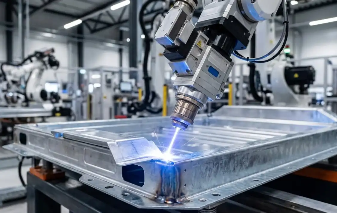
If you’re joining 2–3 mm aluminum to 1–2 mm galvanized steel for an EV battery tray, the real enemy isn’t only brittle intermetallics—it’s galvanic corrosion at the lap edge and through any porosity paths. Here’s a practical, production‑ready playbook centered on laser brazing/controlled fusion with Zn/Ni interlayer strategies and a validation stack that corrosion engineers can trust.
Key takeaways
- Prioritize laser brazing or low‑heat laser fusion with a nickel interlayer to curb Fe–Al IMCs and improve wetting; then design coatings/sealants to isolate the galvanic couple.
- Validate for corrosion in two stages: screen with neutral salt spray (ASTM B117/ISO 9227), then run automotive‑relevant cyclic tests (ISO 21207 or SAE J2334) before release. Cite and document conditions.
- Manage zinc and heat: maintain controlled gaps for Zn vapor escape, keep linear energy low, and consider beam offset/wobble only as levers to stabilize wetting and limit IMC growth.
- Inspect what you can’t see: use radiography/CT for porosity and phased‑array UT for lap‑interface fusion; qualify NDT procedures to the applicable ASTM/ISO families.
When to favor laser brazing vs. controlled fusion
If corrosion resistance is your top KPI, start with laser brazing logic: let the aluminum side wet and bond across an interlayered interface on steel without fully melting deep steel volumes. This typically produces thinner Fe–Al reaction layers and fewer hot‑cracking/porosity risks in the aluminum. Where higher joint strength is mandatory, a tightly controlled fusion pass may be justified—but only with measures that limit time-at-peak temperature and stabilize wetting (interlayers, fit‑up discipline, shielding).
Put differently: if you can meet structural targets through a brazed‑style lap seam plus robust sealing and coating, that path often wins the long corrosion game. Need more strength? Dial toward fusion but keep IMC control front and center.
Surface and coating management on galvanized steel and aluminum
A clean, dry, oxide‑managed surface is non‑negotiable. On aluminum, remove organic contaminants and oxide films using approved mechanical or chemical methods; keep time-to-weld short after preparation. On the galvanized steel, the Zn layer is both friend and foe: it can assist wetting at brazing temperatures yet drives outgassing and porosity when overheated. Practical patterns:
- Localized cleaning or de‑galvanizing in the immediate fusion line can help, but don’t over‑remove zinc where it supports corrosion protection. Ensure any removal strategy is paired with post‑join coating restoration.
- Control lap gap consistently so Zn vapor has a predictable escape path; avoid tight spots that trap gas next to wide gaps that starve capillary flow.
- Fixturing should restrain distortion without crushing the gap; think spring‑loaded or compliant clamping that holds alignment but allows uniform spacing along the seam.
Interlayer strategies with nickel (plating or foil)
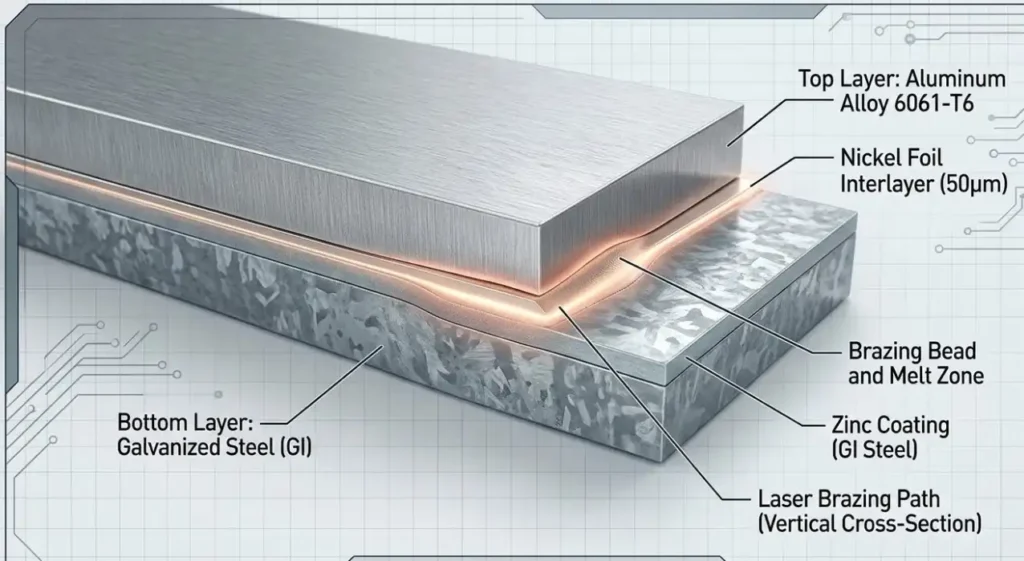
Nickel is a proven go‑between for aluminum/steel couples. Mechanistically, Ni reduces direct Fe–Al reactions, promotes more benign intermetallic phases, and can improve wetting during laser brazing. Two practical implementations:
- Nickel plating on the steel faying surface: consistent, thin, and production‑friendly if you control cleanliness and thickness across the lot. It integrates well with line takt but needs thorough post‑process corrosion planning.
- Nickel foil at the lap: useful when you need a discrete layer and consistent metallurgy; it requires precise placement and tack strategy to prevent foil migration.
In both cases, target uniform coverage at the intended bond line, avoid discontinuities at lap edges, and qualify the interlayer with your specific alloy pairings and coating stack. Because microstructure depends on local heat history, you’ll confirm intermetallic behavior with metallography during procedure qualification rather than rely on generic numbers.
Parameter tuning map for thin lap joints (normalize by energy, not just power)
Rather than lock onto a single “recipe,” normalize by linear energy density (LED) and use beam positioning/shielding as stabilizers. Treat the following as a tuning map that must be shop‑qualified on your equipment and materials.
Typical tuning levers and intent:
- Keep LED low enough to limit Zn vaporization while allowing aluminum-side wetting.
- Consider a small beam offset toward the steel side to pre‑condition the interface during brazing‑style passes; confirm with cross‑sections.
- Use argon as a baseline shielding gas; helium or Ar/He mixes can help reduce porosity but will alter melt dynamics.
Two‑minute map (qualify locally):
| Control knob | Qualitative target | Effect you’re chasing | Trade‑offs to watch |
|---|---|---|---|
| Linear energy density (LED) | Low-to-moderate | Limit Zn outgassing, thin IMC | Too low → lack of wetting; too high → porosity/IMC growth |
| Beam offset (toward steel) | Small, consistent | Pre‑heat/condition interface, stabilize capillary flow | Excess offset → steel melting, IMC thickening |
| Focus position | Slight defocus on Al side | Smoother wetting, lower peak | Over‑defocus → shallow bonding |
| Shielding gas | Ar baseline; evaluate He mix | Reduced porosity, brighter pool | He raises heat extraction; tune LED accordingly |
| Scan/wobble | Narrow amplitude | Even heat, wetting stability | Over‑wobble → excessive dwell/IMC |
| Travel speed | As high as quality allows | Shorten time-at-temp | Too fast → cold lap, discontinuities |
Strong recommendation: build a short Design of Experiments to bracket LED, offset, and shielding on your exact stackup, then metallographically measure the interface and run corrosion screens before scaling.
Defect and corrosion risk mitigation tactics
- Porosity from Zn vapor: reduce LED, provide a controlled escape path, and consider He‑enriched shielding. Keep surfaces dry; residual moisture amplifies gas evolution.
- Brittle intermetallics: favor brazing‑style passes with interlayers; keep time above critical temperatures short via speed, focus, and energy control.
- Distortion and visual quality: clamp smartly with compliant fixtures; use symmetric weld sequences on mirrored parts to balance shrinkage; avoid oversize melt pools.
- Lap‑edge galvanic hot spots: design sealants and coatings to encapsulate the lap edge and block electrolyte ingress; don’t leave capillary paths open to road splash.
Inspection and validation plan (what to prove before SOP)
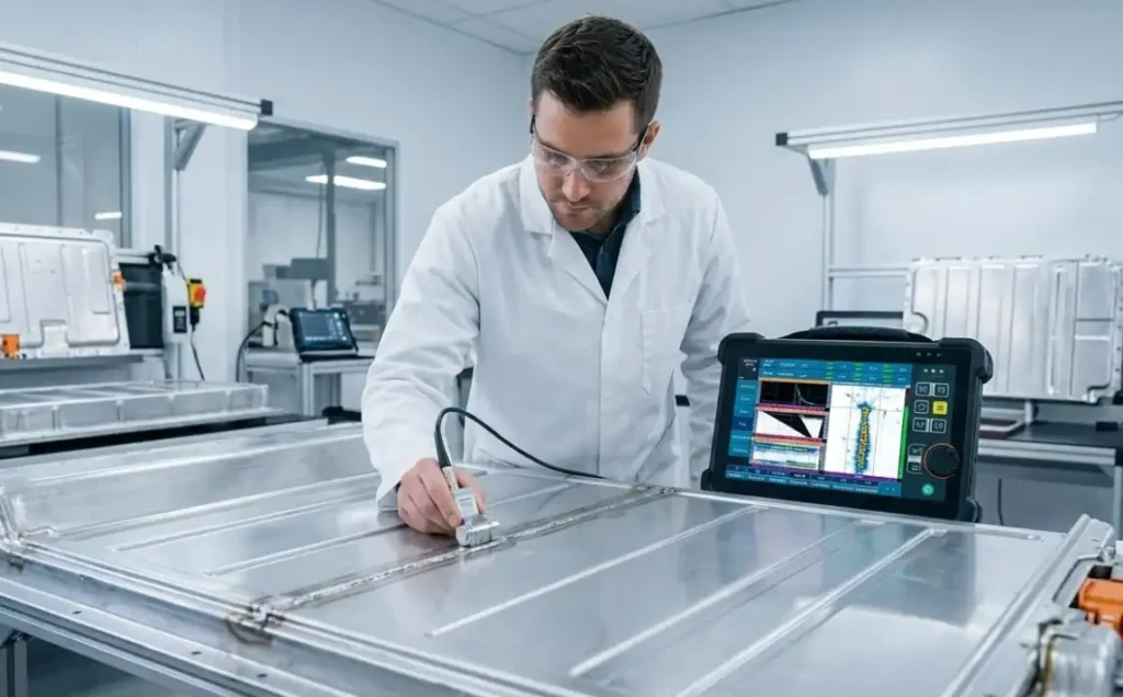
You can’t release on “looks good.” Prove internal quality and corrosion performance with a two‑lane plan:
- Volumetric quality: use radiography or CT to quantify porosity and lack‑of‑fusion. Selection and calibration should follow weld‑inspection standards—see the TWI overview of typical laser weld defects for what to target and how RT can reveal them, and qualify to applicable ASTM/ISO families. See the discussion of common defects in the TWI knowledge base: typical defects in laser welds.
- Planar/interface quality: phased‑array UT helps detect delamination and incomplete bonding in lap joints where access is limited; procedure‑qualify your PAUT settings for thin sections. For fundamentals, TWI’s phased‑array UT overview is a solid primer.
- Corrosion screening: run neutral salt spray to a documented spec. The practice conditions are summarized in ASTM’s Salt Spray (Fog) Practice overview for ASTM B117 and in ISO’s family context for ISO 9227 neutral salt spray. Use these only as screens; they do not predict field life.
- Automotive‑relevant cyclic tests: before SOP, add cyclic exposures such as ISO 21207 composite cycles or OEM‑aligned SAE J2334 to better replicate road conditions (J2334 is gated access; reference it in your control plan).
- Galvanic risk rationale: aluminum is anodic to steels; isolating the lap and edges is essential. AMPP’s article on atmospheric couples provides context on why barriers matter; see AMPP’s discussion of atmospheric galvanic couple corrosion.
Practical example: generic fiber laser + nickel foil lap‑braze (battery tray flange)
A thin‑gauge battery tray side flange in 2.5 mm aluminum overlaps a 1.4 mm galvanized steel reinforcement. After solvent clean and light mechanical oxide management on the aluminum, a nickel foil cut to seam width is placed on the steel faying surface. Compliant clamps set a uniform, shallow lap gap to promote capillary flow and a predictable Zn escape path.
A single‑mode fiber laser head, aligned with a small, consistent offset toward the steel side, traverses the lap at a speed that maintains a bright yet controlled pool on the aluminum. Shielding starts with argon and transitions to a small He mix where porosity trends upward. The foil remains stationary thanks to tack points at the run‑in and exit tabs. Cross‑sections from the qualification builds show a thin, continuous reaction layer with the nickel intermediary and no large porosity clusters.
Quality assurance uses CT sampling to confirm volumetric integrity and PAUT to check for interface discontinuities. Corrosion validation follows a two‑stage plan: neutral salt spray screening, then an ISO 21207 cyclic exposure to verify seam and edge isolation. Results and metallography are captured in the procedure qualification record before moving to rate production.
Post‑join protective finishes and seam isolation
Seal the deal—literally. Conversion coatings or compatible primers on aluminum, zinc‑phosphate/paint systems on steel, and an edge‑focused sealant can drastically reduce galvanic pathways. Whatever stack you choose, validate the combo through B117/ISO 9227 screening and a cyclic profile (ISO 21207 or SAE J2334). AMPP’s corrosion‑prevention principles underscore why barrier systems and electrical isolation at the lap edge matter for longevity.
Pre‑weld and first‑article qualification checklists
Use this short list to keep trials consistent. Adapt to your plant SOP.
- Surfaces cleaned and dry; aluminum oxide managed; galvanized surface condition recorded; interlayer presence/coverage verified.
- Fixturing sets uniform lap gap; clamps are compliant; tack strategy prevents interlayer shift.
- Parameter window defined as LED bands; shielding gas recorded; beam offset documented; run‑in/out tabs present.
- NDT plan approved (RT/CT + PAUT); metallography sampling planned; corrosion test matrix logged (B117/ISO 9227 → ISO 21207 or SAE J2334).
Troubleshooting guide (symptom → likely cause → corrective action)
| Symptom | Likely cause | Corrective action |
|---|---|---|
| Edge porosity clusters | Excess Zn vapor, trapped moisture | Lower LED; ensure uniform lap gap/escape path; dry parts; evaluate He mix |
| Lack of wetting/continuous fillet | Too little heat or poor surface prep | Slightly increase LED or adjust focus; improve oxide removal; confirm interlayer placement |
| Thick/brittle interface | Excess time-at-peak or beam on steel | Increase travel speed; reduce offset; narrow wobble; confirm Ni coverage |
| Discoloration/soot | Contaminants or shielding disruption | Improve cleaning; stabilize gas flow; check nozzle standoff |
| Lap‑edge corrosion after screening | Sealant/coating discontinuity | Rework edge seal; adjust coating stack; retest with ISO 21207 cycle |
H2: Laser welding aluminum to galvanized steel—evidence and next steps
You’ve got a solid framework now: corrosion‑first process selection, disciplined surface/interlayer control, energy‑normalized tuning, and inspections that actually see what matters. The final step is institutionalizing this as a control plan—tighten documentation, run your qualification matrix, and lock settings in MES so drift is visible.
Short CTA: Pilot the brazing‑first approach on your exact stackup, qualify with CT/PAUT plus B117 and ISO 21207, then roll to SOP with documented controls.
References (selected)
- Typical defects and inspection options for laser welds: TWI knowledge base (accessed 2026).
- Phased‑array UT fundamentals relevant to lap seams: TWI PAUT overview (accessed 2026).
- Neutral salt spray practice summary: ASTM’s overview of ASTM B117 (accessed 2026).
- ISO salt spray family and cyclic testing context: ISO 9227 family index and ISO 21207 composite cycles (accessed 2026).
- Galvanic‑couple behavior context: AMPP article on atmospheric galvanic couples (accessed 2026).
Author
Process metallurgist and joining engineer with commissioning experience on high‑volume EV structures. Background in laser joining procedure qualification, metallography, CT/PAUT NDT development, and corrosion validation under B117/ISO 9227 and ISO 21207 profiles.


