If you need clean, low-heat welds on carbon steel precision parts and mold repair—and they must pass AWS/ASME-minded inspection—this step-by-step guide is for you. We’ll work DCEN TIG (aka Heliarc welding) with conservative, repeatable settings, then walk symptom → cause → fix for the defects that actually slow production. Along the way, you’ll see quick parameter checkpoints, verification steps, and compliance notes you can fold into a WPS.
Key takeaways
- Use DC electrode negative (DCEN) for carbon steel; it concentrates heat into the workpiece and stabilizes the tungsten arc. According to the AWS Welding Digest explanation of GTAW (2025), DCEN is the standard selection for steels.
- Start with pure argon and a gas lens; use cups around #5–#8 and the lowest laminar flow that protects the puddle (often ~10–25 CFH for small/medium cups). Shielding fundamentals appear in Miller’s TIG basics guide.
- For thin-to-medium carbon steel, conservative starting envelopes often land around 40–150 A DCEN depending on thickness, with 1/32–3/32 in tungsten sharpened lengthwise. Validate on scrap and log actuals in your WPS.
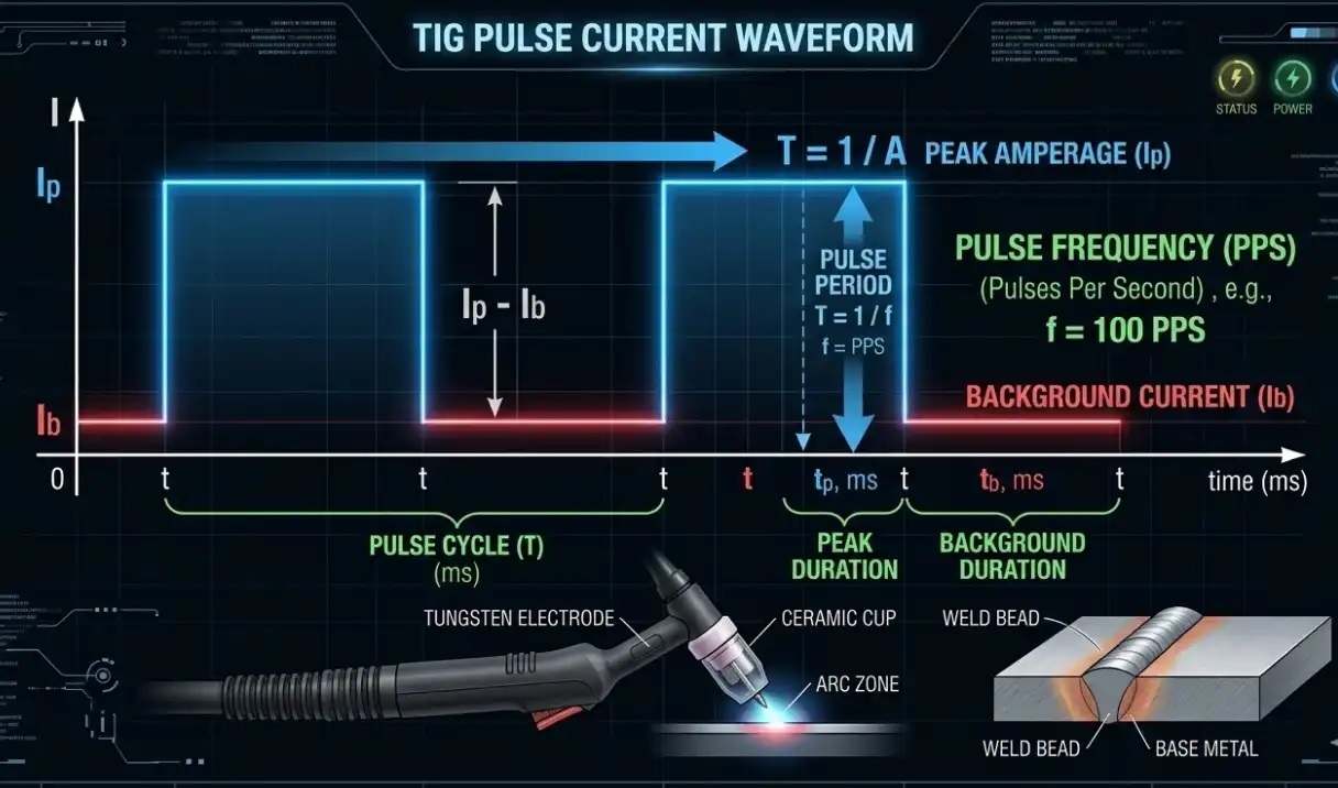
- Pulse TIG helps control heat and distortion. Start with visible control (1–10 PPS) or tighter arc focus (~100 PPS) and tune peak time (about 30–50%) and background (20–40%). Concepts are discussed in Miller’s pulse settings article.
- Choose ER70S-2 for very clean, high-quality deposits or ER70S-6 where wetting on slightly less-than-perfect steel helps. See filler selection context from ESAB’s ER70S explainer.
- Safety is nonnegotiable: manage inert-gas asphyxiation risk and tungsten grinding dust; OSHA and NIOSH guidance offer accessible overviews.
Heliarc welding quick-start parameter checkpoints (validate on scrap and by WPS)
Use these as starting points; qualify on coupons, document actuals, and follow your code/project requirements.
- Polarity: DCEN for carbon steel TIG/GTAW (Heliarc welding). Rationale summarized by AWS Welding Digest (2025).
- Shielding gas: Pure argon baseline; Ar/He only if added heat is essential on thicker spots. Shielding fundamentals in Miller’s coverage article.
- Cups & gas lens: #5–#8 with gas lens; target 10–25 CFH for small/medium cups, increasing if stickout or drafts demand. Torch access may dictate cup downsizing.
- Tungsten (DC): 2% thoriated or 2% lanthanated. Rough guide by section:
- Thin (~1–3 mm / 0.040–0.120 in): 1/32–1/16 in (1.0–1.6 mm), ground to a sharp point; ~40–90 A.
- Medium (~3–6 mm / 0.120–0.250 in): 1/16–3/32 in (1.6–2.4 mm), sharp to slight truncation; ~90–150 A.
- Pulse starters:
- Thin: try 1–10 PPS for visible rhythm or ~100 PPS for tighter arc; 30–50% peak time; 20–40% background.
- Medium: 50–150+ PPS; 40–60% peak time; background tuned for puddle support with minimal heat.
- Filler: ER70S-2 for cleaner deposits; ER70S-6 for good wetting on clean mild steels. Match wire diameter to joint size and target heat input.
Pro tip: Keep tungsten stickout short (3–5 mm) when access allows; with a gas lens, a working limit near the cup’s ID is common for #5–#8 cups. Excess stickout often shows up later as porosity or arc wander.
Porosity — stop it before you start
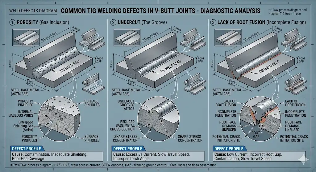
Symptoms: pinholes, scattered/frequent pores, dull/sooty discoloration.
Likely causes: inadequate shielding (low/erratic flow, drafts), contamination (base/filler/tungsten), long arc length, wet filler.
Step-by-step repair recipe
- Prep to bright metal: remove oil/paint/oxide; dry rods. Shorten arc length immediately. See contamination and shielding notes in Miller’s defect guide and porosity causes summarized by TWI.
- Shielding setup: gas lens + cup #5–#7, argon ~10–15 CFH in calm air; increase only enough to maintain color. Block drafts.
- Parameters: Thin sections start ~40–80 A DCEN; pulse 1–10 PPS (or ~100 PPS), 30–45% peak, 20–30% background. Use 1/16 in 2% La/Th tungsten, sharp point.
- Technique: Tight arc (≈1–1.5× tungsten diameter), slight push angle (~10–15°), dab dry filler within the shielding envelope.
- Rework: If porosity is found, grind to sound metal and re-weld with improved shielding.
Verification checkpoints
- VT: bead shows metallic sheen, no soot; consistent color banding indicates good post-flow; no visible pores under 10× loupe.
- If recurring pores appear in critical areas, run PT (dye penetrant) after blending to confirm surface soundness before release.
Prevention checklist
- Leak-check gas system; verify cylinder purity.
- Dedicated tungsten grinder and clean wire storage.
- Maintain post-flow long enough to cover the cooling puddle and tungsten.
Undercut — fill the edge, don’t melt it away
Symptoms: groove melted along the toe, thinning the parent metal at the edge.
Likely causes: excessive amperage, fast travel, torch angle pushing arc off the root/sidewall, low filler deposition rate.
Step-by-step repair recipe
- Reduce heat or increase metal deposition: drop peak amps 5–15% or slow travel; in pulse mode, consider increasing background current slightly for puddle support.
- Torch control: Aim arc toward the edge you’re washing; keep angle shallow (≈10–15°) and arc short.
- Filler timing: Increase feed rate and synchronize dabs at peak to support the toes.
- Parameters: For fillets on ~3 mm material, a starting window around 90–110 A DCEN with 3/32 in tungsten and #6–#7 cup at ~12–16 CFH often stabilizes the toe.
Verification checkpoints
- VT: smooth transition with no visible groove; fillet throat meets specified dimension (confirm with a fillet gauge).
Prevention checklist
- Practice beads-on-plate to balance heat vs filler rate.
- Log successful settings in your WPS notes for similar geometries.
Lack of penetration or fusion — open the root and wash the sidewalls
Symptoms: cold lap, stacked-but-unfused layers, incomplete root penetration.
Likely causes: low heat, fast travel, long arc, poor fit-up, misdirected arc.
Step-by-step repair recipe
- Fit-up first: ensure root opening and alignment match the joint design. Clean interpass.
- Direct the energy: angle the torch to drive the arc into the root/sidewall; shorten the arc.
- Parameters: Increase peak amps 5–20% or reduce background; slow slightly to allow sidewall wash-in. Thin sections: 60–90 A DCEN; medium: 110–150 A depending on joint.
- Pulse tuning: Lower PPS into the 1–10 range if you need visible puddle agitation for sidewall fusion.
Verification checkpoints
- VT: etched/consistent bead toe; no cold lap. For critical joints, section a coupon or perform PT/UT per project requirements.
Prevention checklist
- Choose filler diameter appropriate to joint size (too large chills puddle; too small won’t support toes).
- Keep arc length tight to concentrate heat into the root.
Tungsten contamination — if you dip, stop and regrind
Symptoms: erratic arc, black specks in puddle, crater inclusions, tungsten balling on tip (DC).
Likely causes: dipping tungsten into puddle, too small a tungsten for current, incorrect prep/polarity, drafts causing arc wander.
Step-by-step repair recipe
- Stop: regrind tungsten lengthwise to a sharp point; add a tiny flat if tip erosion is frequent. Confirm DCEN polarity.
- Right-size the electrode: upsize tungsten or trim peak amps 5–15% to stay within a stable window.
- Shielding discipline: use a gas lens; reduce stickout; maintain post-flow so the tungsten cools under gas.
- Technique: Keep a shorter arc and improve hand rest to avoid dips.
Verification checkpoints
- Stable, centered arc; smooth bead without peppered inclusions; tungsten tip maintains shape across short runs.
Prevention checklist
- Dedicated grinder/extraction; PPE for grinding dust per NIOSH tungsten dust guidance.
- Check for drafts and hose leaks to prevent arc wander.
Distortion control — keep parts straight and molds in tolerance
Symptoms: warping, dimensional shift, high residual stresses making finishing unpredictable.
Likely causes: excessive heat input (high amps, long arc, slow travel), poor sequencing, insufficient restraint.
Step-by-step repair recipe
- Plan restraint and sequence: clamp/fixture; alternate sides; use tacks to lock geometry. For cosmetic surfaces, plan minimal, distributed passes.
- Use pulse: start ~100 PPS (or visible 1–10 PPS if you prefer cadence), ~40% peak time, ~25–35% background. Run smaller, faster beads.
- Heat sinks and pauses: apply copper/aluminum heat sinks where appropriate; allow short cools while maintaining shielding where feasible.
- Parameters: Favor the low end of amperage ranges that still achieve fusion; a tight arc and steady travel speed do more than raw amperage reductions alone.
Verification checkpoints
- Dimensional check after each short run; measure critical features before moving to the next area.
Prevention checklist
- Log pulse and travel speed that met tolerance on similar jobs.
- For tool/mold steels, consider controlled preheat/interpass and slow-cool per supplier data.
Arc instability — tighten the system
Symptoms: wandering arc, difficulty starting, sputtering sound, inconsistent bead.
Likely causes: contaminated tungsten/base, poor gas coverage, wrong polarity/tungsten size, loose electrical connections, long arc, nearly empty cylinder.
Step-by-step repair recipe
- Refresh the electrode: clean/regrind tungsten lengthwise; confirm correct diameter for current.
- Gas and polarity: verify DCEN; check CFH and cup/gas lens; block drafts; confirm gas purity.
- Electrical path: clean ground clamp area; tighten connections; inspect cables for damage.
- Parameters: Use a slightly higher PPS (e.g., 50–100) to stabilize arc force if your machine allows, then fine-tune.
Verification checkpoints
- Consistent, centered arc cone; uniform bead appearance; reliable starts without wandering.
Prevention checklist
- Routine equipment inspection; replace worn consumables; maintain a shielding discipline checklist.
Precision mold repair notes (carbon/tool steels)
For mold components and precision tooling, minimizing residual stress and maintaining surface quality are everything. Tool steel suppliers advise controlled preheat/interpass and slow cooling to avoid cracking and distortion. Uddeholm notes that many tool steels benefit from preheating around the 200–250°C (390–480°F) band with maintained interpass and controlled cool, followed by tempering or stress relief depending on grade; see high-level guidance in Uddeholm’s welding of tool steels document.
Practical checklist
- Preheat per the steel’s datasheet when required; monitor interpass; avoid quenching effects.
- Use small, pulsed beads and blend while warm to reduce rework on cosmetic surfaces.
- Plan finishing: leave allowance for machining/polishing; verify hardness targets after any temper/stress-relief cycle.
WPS and compliance pointers
- Record what actually worked: amperage window, pulse settings, tungsten type/size, cup and CFH, filler class/diameter, travel speed notes.
- Remember essential variables under ASME Section IX concepts: significant changes in process, polarity, base metal group, filler class/diameter, shielding gas/mix, or heat input may require requalification.
- Keep batch certs for ER70S-x fillers (AWS A5.18 family) and shielding gas specs with your WPS.
- For structural carbon steel acceptance and preheat/interpass methodology, reference code intent in AWS D1.1/D1.1M; use project-specific acceptance criteria instead of generic internet tables. The public index is here: AWS D1.1/D1.1M 2020 index.
Inspection and acceptance on the shop floor
- Visual examination: cleanliness, fit-up, bead profile, toe blending, absence of cracking, and color/oxidation cues indicating adequate shielding and post-flow. Practical TIG technique reminders appear in ESAB’s TIG practice guide.
- When to use PT/DPI: after blending repairs or for critical surfaces where surface-breaking flaws must be ruled out; TWI discusses PT within broader repair/NDI context in its code comparison article.
- Safety reminders: manage inert-gas risk per OSHA’s welding fact sheet and tungsten/carbide grinding dust per NIOSH guidance.
Wrap-up
Heliarc welding on carbon steel precision parts and mold repair comes down to disciplined setup, tight arc control, and smart use of pulse to tame heat and distortion. Use the starting envelopes here, verify on scrap, and capture the parameters that pass inspection. Once you’ve got a repeatable recipe, your WPS and your parts will both look a whole lot better.
See also
Analysis of the causes of cracks in laser welded carbon steel
Shielding Gas: Nitrogen vs. Argon in Laser Welding


