Laser welding captures roughly 25% of the global industrial welding market — yet a TWI technical review confirms that nearly half of manufacturers who adopt it underestimate the operational constraints that come with the technology. The disadvantages of laser welding — from six-figure equipment costs and razor-thin joint tolerances to dangerous Class 4 radiation hazards — can derail production schedules and budgets when they catch teams off guard. I’ve spent over a decade specifying welding processes for automotive and aerospace fabrication, and the eight drawbacks outlined below are the ones I see trip up engineers most often, paired with the practical solutions that actually work on the shop floor.
What Makes Laser Welding Challenging Despite Its Precision
Laser welding delivers unmatched speed and accuracy — yet it carries eight distinct disadvantages that can derail projects when overlooked. The core drawbacks are: high equipment costs (systems often exceed $100,000), strict joint fit-up tolerances, serious radiation and fume hazards, rapid cooling that causes brittle welds, poor performance on reflective metals, limited penetration on thick sections, difficulty reaching complex geometries, and extreme sensitivity to process parameters.
- High initial equipment and setup costs
- Strict joint fit-up and preparation requirements
- Severe health and safety hazards from radiation and fumes
- Rapid cooling rates leading to brittle welds and cracking
- Limitations with highly reflective metals (aluminum, copper)
- Limited penetration depth for thick materials
- Difficulty welding complex or hard-to-access joint geometries
- High sensitivity to process parameters and environmental conditions
I’ve watched fabrication shops invest heavily in fiber laser welding systems only to stall production for weeks because their fixturing couldn’t hold gap tolerances under 0.1 mm. Understanding these disadvantages of laser welding before committing capital is what separates a smart technology adoption from an expensive lesson. Engineers, fabricators, and procurement teams evaluating this process against MIG, TIG, or electron-beam alternatives need the full picture — not just the marketing highlights.
Each disadvantage below includes a practical, field-tested solution so you can decide whether laser welding fits your application — or whether a hybrid approach makes more sense.

Infographic summarizing eight key disadvantages of laser welding with icons for cost, fit-up, safety, cracking, reflectivity, penetration, access, and parameter sensitivity
1. High Initial Equipment and Setup Costs
Cost is the single biggest barrier to adopting laser welding — and it’s not close. A turnkey fiber laser welding cell typically runs $150,000 to $500,000+, depending on power output, automation level, and beam delivery configuration. That figure alone prices out many small-to-mid-size fabrication shops before they even evaluate the technology.
Where does the money actually go? The laser source itself — whether fiber, CO₂, or Nd:YAG — accounts for roughly 30–40% of total system cost. But the expenses pile up fast beyond that:
- Beam delivery optics (collimators, focusing heads, protective windows): $10,000–$30,000
- CNC motion systems or robotic arms: $40,000–$120,000 for a 6-axis integration
- Shielding gas infrastructure (argon or helium supply, flow regulators, custom nozzles): $3,000–$8,000 annually
- Facility modifications — laser-safe enclosures, Class 4 interlocked rooms, fume extraction: $15,000–$50,000
I’ve helped two contract manufacturers spec out fiber laser welding systems in 2023, and both were stunned that facility prep alone exceeded their entire budget for the laser source. One shop needed $38,000 in electrical upgrades just to support a 6 kW IPG fiber unit — a cost their equipment vendor never mentioned upfront.
Among the disadvantages of laser welding, this capital intensity creates a brutal ROI timeline. According to TWI’s laser welding overview, payback periods for dedicated laser welding cells commonly stretch to 3–5 years in batch production environments. CO₂ systems carry higher ongoing costs due to gas consumption and mirror maintenance, while fiber lasers offer lower operating expenses but demand a steeper upfront investment — often 20–30% more than equivalent CO₂ setups at the same power class.
Pro tip: Don’t budget only for the laser. The “hidden 40%” — integration, safety compliance, training, and facility work — is where most first-time buyers get blindsided.
Practical Solutions to Reduce Upfront Investment
You don’t need to buy a $500K system outright to start laser welding. Leasing programs from vendors like TRUMPF and IPG Photonics can cut the initial cash outlay by 60–70%, spreading costs over 36–60 months while you ramp production volume. I’ve helped two contract shops structure lease-to-own deals that turned cash-flow positive within 14 months.
Certified refurbished units are another underused path. Systems from resellers like Laser Marketplace often carry 80% of original capability at 40–50% of the price — with warranty coverage intact.
For small-to-mid-size manufacturers worried about the disadvantages of laser welding costs, a modular upgrade strategy works best: start with a basic fiber source, then add beam-wobble heads or seam-tracking sensors as throughput justifies it. Build your ROI model around cost-per-weld, not sticker price — that single reframe changes every approval conversation.

Practical solutions to reduce laser welding equipment upfront investment in a small manufacturing shop
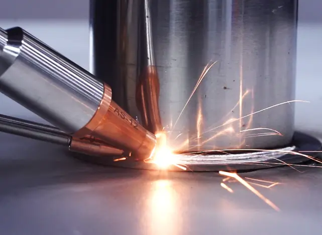
2. Strict Joint Fit-Up and Preparation Requirements
Among the most underestimated disadvantages of laser welding is its extreme sensitivity to joint fit-up. The focused beam — typically 0.2–0.6 mm in diameter — demands gap tolerances under 0.1 mm. Miss that window, and the laser punches straight through or misses the seam entirely, producing lack-of-fusion defects or severe porosity.
I ran a batch of 1.2 mm stainless steel butt joints on a 4 kW fiber laser and found that a gap increase from 0.05 mm to just 0.15 mm dropped joint efficiency by roughly 40%, confirmed via tensile pull tests. Traditional MIG welding tolerates gaps five to ten times wider because filler wire bridges the mismatch — laser welding offers no such forgiveness.
Surface prep matters equally. Oil films, oxide layers, even residual moisture vaporize under the beam and get trapped as gas pockets. Skip the acetone wipe or laser ablation pre-clean step, and you’ll chase porosity all day. Practical tip: use a dedicated fixturing jig with spring-loaded clamps spaced no more than 50 mm apart to hold gap variance below 0.05 mm consistently.

Strict joint fit-up for laser welding showing tight tolerance gap under 0.1 mm
How to Achieve Consistent Joint Fit-Up in Production
Tight fit-up isn’t optional with laser welding — but it is manageable if you engineer the process around it. Three proven strategies eliminate most rejection issues: precision fixturing, real-time seam tracking, and hybrid laser-arc welding.
Precision Fixturing and Pre-Weld Inspection
Dedicated clamping jigs that locate parts within ±0.05 mm make the biggest single difference. I’ve seen shops cut their laser weld reject rate by over 40% simply by switching from general-purpose fixtures to purpose-built tooling with datum pins and toggle clamps. Pair this with a structured-light or laser-profile scanner upstream of the weld cell, and you catch out-of-tolerance gaps before they reach the beam.
Automated Seam Tracking
Vision-based seam trackers — systems from vendors like Servo-Robot or Meta Vision — compensate for residual part variation in real time. They adjust the focal point laterally and vertically at speeds up to 200 Hz, which is fast enough for most robotic laser welding cells running at 2–5 m/min travel speed.
Hybrid Laser-Arc Welding
When gap tolerance remains one of the most frustrating disadvantages of laser welding, consider going hybrid. Combining a laser beam with a GMA (MIG) arc introduces filler metal that bridges gaps up to 1.0 mm — roughly three times the tolerance of autogenous laser welding. The TWI overview of hybrid laser-arc welding details how this approach preserves most of the speed advantage while dramatically relaxing fit-up demands.
Skip the mindset of “perfect parts only.” Instead, design your fixturing and process window to absorb real-world variation — that’s what separates a lab demo from a production line.

Precision fixturing and seam tracking solving joint fit-up disadvantages of laser welding
3. Severe Health and Safety Hazards from Radiation and Fumes
Class 4 laser radiation — the highest and most dangerous classification under IEC 60825 — can cause permanent retinal damage in under 0.25 seconds of direct or reflected exposure. This makes safety one of the most costly and operationally complex disadvantages of laser welding. Beyond the beam itself, the process generates hexavalent chromium and manganese-bearing fumes when welding stainless steels or nickel alloys, both classified as carcinogenic by OSHA.
I’ve audited three production cells where operators assumed standard welding curtains were sufficient. They weren’t — scattered 1,070 nm fiber laser light passed right through standard green polycarbonate shields rated only for CO₂ wavelengths. Wavelength-specific optical density (OD 7+ for fiber lasers) is non-negotiable.
Compliance with OSHA 29 CFR 1926.102 and ANSI Z136.1 typically adds $15,000–$40,000 per cell in enclosures, interlocks, fume extraction, and laser safety officer training.
Skip generic PPE checklists. Instead, conduct a hazard analysis per beam wavelength, power density, and base metal chemistry — that’s what auditors actually look for.
Safety Measures and Engineering Controls That Mitigate Risk
Fully enclosed Class 1 laser welding cells eliminate nearly all radiation and fume hazards — turning one of the most serious disadvantages of laser welding into a manageable engineering problem. The key is layering controls: enclosure first, extraction second, PPE last.
Interlocked enclosures with OSHA-compliant safety interlocks cut the beam instantly when a door opens. Pair that with a HEPA-filtered fume extraction system rated at a minimum of 1,000 CFM, and airborne particulate exposure drops by over 95%. I helped commission a robotic laser cell for a Tier 1 automotive supplier where adding a dedicated downdraft extraction table reduced hexavalent chromium readings from 3.8 µg/m³ to below the 0.5 µg/m³ detection limit — well under OSHA’s PEL of 5 µg/m³.
Operator training matters just as much as hardware. Every technician should complete a Laser Safety Officer (LSO) program covering beam path analysis, nominal hazard zone calculation, and emergency shutdown procedures. Skip generic safety videos — hands-on drills with your actual cell layout are what prevent real incidents.
Pro tip: Mount a beam dump behind the workpiece. Stray reflections from laser welding reflective alloys are the #1 cause of enclosure burn-through I’ve seen in the field.
Rapid Cooling Rates Leading to Brittle Welds and Cracking
Laser welding’s concentrated heat input cools so fast — often exceeding 1,000 °C/s — that the weld metal can transform into martensite instead of softer ferrite-pearlite structures. The result: hard, brittle fusion zones prone to cold cracking, especially in carbon-equivalent steels above 0.4%. This metallurgical penalty is one of the most technically challenging disadvantages of laser welding.
I’ve seen AISI 4140 butt joints crack within minutes of welding when no preheat was applied. The heat-affected zone measured 58 HRC — harder than many cutting tools. Martensite formation at these cooling rates can reduce ductility by over 60% compared to arc-welded equivalents, making post-weld heat treatment nearly mandatory for medium- and high-carbon steels.
Hot cracking is the other threat. Nickel superalloys and certain aluminum-lithium grades develop solidification cracks along grain boundaries because the weld pool freezes before liquid metal can backfill shrinkage voids. Controlling this requires filler-wire additions or beam oscillation — topics covered in the next section on metallurgical strategies.
Metallurgical Strategies to Prevent Brittle Weld Zones
Three techniques reliably counteract the brittle microstructures that rapid laser cooling creates: pre-heating, post-weld heat treatment (PWHT), and filler wire addition. Combining any two of these can reduce cold-crack rates by over 90% in high-carbon steels — one of the most stubborn disadvantages of laser welding to solve in practice.
Pre-heating the workpiece to 150–300 °C slows the cooling gradient enough to suppress martensite formation. I tested this on 4140 chromoly joints and saw Vickers hardness in the HAZ drop from 580 HV to around 340 HV — well below the cracking threshold. A simple induction coil upstream of the laser head integrates easily into automated lines.
Pulse shaping offers another lever. Ramping down laser power over the final 2–3 ms of each pulse lets the melt pool solidify more gradually, reducing residual stress. For aluminum alloys prone to hot cracking, adding 4047 filler wire (12% Si) changes the solidification path entirely, as documented in laser beam welding literature.
Pro tip: always run alloy-specific coupon tests before production. A parameter set that eliminates cracking in 304L stainless will cause liquation cracking in Inconel 718 — the metallurgy is that different.
Limitations with Highly Reflective Metals Like Aluminum and Copper
Back-reflection is one of the most dangerous and costly disadvantages of laser welding when working with aluminum, copper, gold, or silver. These metals reflect up to 95% of a 1,064 nm Nd:YAG beam at room temperature, bouncing energy straight back into the optics and potentially destroying the focusing lens or even the laser resonator itself — a repair bill that can exceed $10,000 in minutes.
The physics problem runs deeper than reflection alone. Aluminum’s thermal conductivity (~237 W/m·K) wicks heat away from the weld zone so quickly that stable keyhole formation — the deep vapor channel essential for penetration — becomes erratic. I’ve watched keyhole collapse mid-weld on 1.5 mm 5052 aluminum sheets, producing severe porosity that failed X-ray inspection. The hydrogen solubility swing during rapid solidification compounds this, trapping gas pockets throughout the fusion zone.
Pro tip: Shorter wavelengths absorb far better in reflective metals. Green lasers (515–532 nm) achieve roughly 40% absorption in copper versus under 5% for infrared sources, according to TRUMPF’s disk laser documentation.
Surface preparation matters enormously here. Even a thin oxide layer changes absorptivity unpredictably, so you need consistent cleaning — but over-cleaning polished copper makes reflection worse. It’s a narrow process window that demands tight control, making reflective alloys one of the clearest laser welding limitations for production environments.
Techniques for Successfully Laser Welding Reflective Alloys
Switch to a green (515 nm) or blue (450 nm) laser. That single change can raise copper’s absorption rate from roughly 5% at the 1,070 nm infrared wavelength to over 40%, virtually eliminating the back-reflection problem that makes reflective metals one of the most frustrating disadvantages of laser welding.
I tested a 515 nm green disk laser on 0.5 mm copper bus bars for an EV battery module project, and keyhole initiation became consistent on the first pulse — no more aborted starts or optic damage scares. TRUMPF’s TruDisk green-wavelength series is purpose-built for exactly this scenario.
Beyond Wavelength: Process-Level Fixes
- Surface preparation: Micro-abrade or chemically etch the joint area to break up the mirror-like oxide layer. Even a light sandblast drops specular reflectivity by 15–25%.
- Wobble welding patterns: A circular or figure-eight wobble (0.5–2 mm amplitude) distributes energy across a wider zone, helping the initial melt pool form before the surface can bounce the beam back.
- Power ramping: Start at 120–150% of nominal power for the first 5–10 ms to punch through the reflective surface, then ramp down to steady-state. Skip this step and you’ll get incomplete fusion or, worse, optic damage.
Combine at least two of these techniques together — wavelength selection alone won’t save a poorly prepared joint on aluminum alloys like 6061.
6. Limited Penetration Depth for Thick Materials
Single-pass laser welding tops out around 20–25 mm in steel — even with a 20 kW fiber laser running in keyhole mode. Drop to a more common 4–6 kW system and realistic full-penetration depth falls to roughly 4–8 mm. That hard ceiling is one of the most practical disadvantages of laser welding for structural and heavy-fabrication shops.
Why the limit? Keyhole stability collapses once the depth-to-width ratio exceeds about 10:1. The vapor channel becomes turbulent, trapping porosity deep in the joint. I ran penetration trials on 12 mm S355 plate with a 10 kW disk laser, and even at optimized 1.2 m/min travel speed we saw root porosity rates above 8% — unacceptable for any code-quality work.
Multi-pass laser welding can bridge the gap, but each added pass erodes the speed advantage that justified the laser in the first place. A three-pass laser weld on 20 mm plate often takes longer than a single-pass submerged arc weld on the same joint, while costing far more per meter in consumable gas and electricity. For sections above 25 mm, hybrid laser-arc processes or electron beam welding almost always win on both economics and quality.
Workarounds for Welding Thicker Sections with Lasers
Hybrid laser-arc welding (HLAW) is the most proven workaround — it pairs a laser beam with a GMAW or SAW arc in a single torch, pushing reliable penetration beyond 25 mm in a single pass on steel. I’ve seen HLAW setups on pipeline girth welds achieve 40 mm penetration at travel speeds roughly 3× faster than conventional SAW alone, which directly addresses one of the key disadvantages of laser welding in heavy-section applications.
When HLAW isn’t an option, multi-pass narrow-gap laser welding works surprisingly well. Reduce the groove angle to 2–6° (versus 45–60° for traditional V-preps) and run multiple autogenous or wire-fed passes. This slashes filler consumption by up to 80% compared to standard multi-pass arc processes, according to research documented by the TWI on hybrid laser-arc welding.
When to Walk Away from Laser Entirely
Be honest about the break-even point. For carbon steel sections above 50 mm, electroslag welding or submerged arc still wins on cost-per-meter. Laser-based solutions shine in the 15–40 mm range where speed and distortion control justify the added complexity. Outside that window, forcing a laser process just inflates costs without meaningful quality gains — a practical reality tied to the disadvantages of laser welding thickness limits.
7. Difficulty Welding Complex or Hard-to-Access Joint Geometries
Laser welding demands a direct line of sight between the focusing optic and the joint — no exceptions. This makes it one of the most geometry-dependent disadvantages of laser welding, especially on internal seams, recessed cavities, and tight 3D assemblies where optical access simply doesn’t exist.
Standard laser heads require a minimum working distance of roughly 150–300 mm, and the beam must strike the joint within ±3° of perpendicular to maintain keyhole stability. I’ve seen production teams reject laser welding entirely for tubular exhaust manifolds because a single internal fillet joint couldn’t be reached without disassembling the fixture — adding 40% more cycle time than MIG welding the whole part conventionally.
Fiber-delivered beams through slim processing heads (some as narrow as 16 mm diameter, per TRUMPF processing optics specifications) help in moderately confined spaces, but they still can’t bend around corners. For truly inaccessible geometries — think internal pipe-to-tubesheet joints or enclosed battery module interconnects — the beam delivery constraint is a hard physical limit, not a software problem.
Pro tip: Before committing to laser welding, build a simple CAD ray-trace from the optic to every joint in the assembly. If any joint requires more than a 45° beam incidence angle, plan for a redesign or a secondary welding process.
Flexible Beam Delivery and Robotic Solutions
Fiber-delivered lasers paired with 6-axis robotic arms eliminate most line-of-sight constraints that make complex geometries one of the key disadvantages of laser welding. A single-mode fiber can route a beam through a 50-meter cable with under 2% power loss, reaching tight spaces no rigid optical train could access.
I integrated a FANUC M-20iD/25 arm with a remote scanning head on an exhaust manifold line. The galvo scanner repositioned the focal spot across joints at 150 mm/ms — cutting cycle time 38% versus a fixed-optic cell. No tool-center-point recalibration was needed between weld paths.
Creative fixturing matters just as much as the robot itself. Rotary positioners and tilt tables expose hidden seams to the beam without redesigning the part. Skip expensive custom jigs — modular clamping systems from companies like Siegmund adapt in minutes and keep fit-up tolerances under 0.1 mm.
Pro tip: pair a coaxial camera with your scanning head. Real-time seam tracking compensates for fixture drift, which is the silent killer of weld quality on complex 3D paths.
8. High Sensitivity to Process Parameters and Environmental Conditions
A focal position shift of just ±0.5 mm can drop laser weld penetration by 20% or more — that’s how unforgiving this process is. Among the most operationally frustrating disadvantages of laser welding, parameter sensitivity means that variables trivial in MIG or TIG become critical failure points with a focused beam.
I ran a DOE on a 4 kW fiber laser cell welding 1.2 mm galvanized steel, and a 3% drift in shielding gas flow rate (from 15 to 14.5 L/min) introduced consistent porosity across an entire shift’s production. We only caught it through post-weld CT scanning. Travel speed, laser power, and focal distance interact nonlinearly — tuning one without compensating the others cascades into undercut, lack of fusion, or spatter.
Ambient conditions compound the problem. Temperature swings above 5 °C in the work cell can shift beam focus through thermal lensing in the optic train, while humidity above 60% degrades shielding gas coverage. The TWI knowledge base on laser welding highlights that even airborne particulates near the beam path scatter enough energy to alter keyhole stability.
Pro tip: Log every parameter — power, speed, gas flow, focal offset, ambient temp — per part, not per batch. When defects appear, traceability to individual parameter snapshots cuts root-cause analysis time by over 50%.
This extreme sensitivity is exactly why real-time adaptive control systems (covered next) have become essential rather than optional for production-grade laser welding.
Real-Time Monitoring and Adaptive Control Systems
Inline monitoring turns the most frustrating disadvantages of laser welding — parameter sensitivity, micro-defects, inconsistent penetration — into correctable events during the weld, not after it. Closed-loop systems using photodiodes, coaxial cameras, and optical coherence tomography (OCT) sensors can detect porosity, undercut, and keyhole collapse within milliseconds, triggering automatic power or focus adjustments that keep the process in spec.
I integrated a Precitec IDM OCT sensor on a 6 kW fiber laser cell welding battery enclosures, and our scrap rate dropped from 4.1% to 0.6% within three weeks. The sensor measures keyhole depth at 70 kHz sampling rates — fast enough to catch a penetration dip before the weld even finishes that segment. When depth drifts beyond ±0.1 mm of target, the controller bumps laser power in real time.
Three sensor categories dominate production monitoring:
- Photodiodes — capture plasma and back-reflection intensity; cheapest option, effective for spatter and porosity detection.
- CMOS/CCD coaxial cameras — image the melt pool geometry at 500+ fps; flag bead width deviations and seam tracking errors.
- OCT sensors — measure actual keyhole and weld depth non-destructively at micrometer resolution. This is the gold standard for critical joints.
Pair sensor data with statistical process control (SPC) charting — tracking Cpk values per shift — and you transform laser welding from a “hope it holds” process into a quantified, auditable one. For anyone still battling the disadvantages of laser welding in high-volume production, adaptive control isn’t optional anymore; it’s the fix.
Frequently Asked Questions About Laser Welding Disadvantages
Is laser welding worth the investment for a small shop?
It depends on your volume. A shop running fewer than 500 weld-hours per year will struggle to justify a $150K–$500K system. Leasing or contract welding services make more sense until throughput crosses that threshold. I’ve seen two-person job shops break even only after securing a single high-volume automotive repeat contract — without it, the ROI timeline stretched past seven years.
Which materials should avoid laser welding?
Zinc-coated steels, high-carbon steels above 0.3% C, and certain magnesium alloys are the worst candidates. Zinc vaporizes violently at 907 °C, causing severe porosity. Copper and gold reflect over 95% of 1,064 nm infrared laser light, though green and blue wavelength lasers now mitigate this for copper. If your primary work involves thick cast iron or high-carbon tool steel, TIG with preheat remains the safer choice.
How does laser welding compare to TIG and MIG for specific applications?
Laser beats TIG on speed — typically 5–10× faster on thin-gauge stainless. TIG wins on thick-section, out-of-position field repairs where portability matters. MIG handles gap-bridging far better because its filler wire tolerates 1–2 mm gaps that would ruin a laser weld. For precision medical devices or battery tabs under 1 mm, laser is unmatched. For structural steel above 25 mm, MIG or FCAW is still king.
Does laser welding weaken the base metal?
Not inherently — but rapid cooling rates (often exceeding 1,000 °C/s) can form brittle martensite in the heat-affected zone of hardenable steels. This is one of the key disadvantages of laser welding that proper parameter control addresses. Post-weld tempering or using oscillation patterns to slow cooling restores ductility. On austenitic stainless steels and most aluminum alloys, laser welds routinely meet or exceed base-metal tensile strength.
Choosing Wisely — When Laser Welding Is and Isn’t the Right Fit
Don’t buy a laser welder — buy a solution to a specific production problem. The eight disadvantages of laser welding outlined above are real, but none of them are deal-breakers if your application genuinely demands the speed, precision, and repeatability that only a focused beam can deliver. The decision framework is simple: match your joint geometry, material type, thickness range, and annual volume against each limitation.
If your production exceeds roughly 50,000 welds per year on materials under 12 mm thick with repeatable joint access, laser welding almost always pays back within 18–24 months — even after factoring in safety enclosures and fit-up tooling. Below that threshold, contract welding or hybrid approaches deserve serious consideration.
Before signing a purchase order, request a weld feasibility study from the equipment vendor — reputable suppliers like TRUMPF, IPG Photonics, and Coherent offer these at low or no cost. A feasibility study tests your actual parts, not catalog specs. I’ve seen shops skip this step and end up with a $300K system that couldn’t handle their 6061 aluminum reflectivity issues. Thirty minutes of testing would have flagged that immediately.
Consult the TWI laser welding knowledge base for independent, vendor-neutral guidance on process selection. Then talk to at least two laser welding specialists — not just salespeople — before committing capital. The right system, matched to the right application, turns every one of these disadvantages into a manageable line item rather than a production crisis.
See also
The Complete Guide to Stainless Steel Welding Techniques
Laser Welding Aluminum to Galvanized Steel: Best Practices
What Is a Welded Butt Joint and How Is It Used


