Between 2017 and 2023, collaborative robot installations grew by over 50% annually — yet OSHA incident reports show that roughly 1 in 10 cobot-related workplace injuries stem from incomplete or skipped risk assessments. A thorough cobot risk assessment checklist isn’t optional paperwork; it’s the single most effective tool for preventing contact injuries, ensuring ISO/TS 15066 compliance, and keeping your collaborative application legally defensible. This 47-point checklist walks you through every critical evaluation — from pre-deployment task analysis and force-limit verification to residual risk documentation — so you can deploy cobots that are genuinely safe, not just marketed as safe.
What Makes Cobot Risk Assessment Different from Traditional Robot Safety
Traditional industrial robots operate behind physical barriers — cages, light curtains, safety fences. The entire safety philosophy boils down to one word: separation. Keep humans out, and the robot can move at full speed with maximum force. A cobot flips that model entirely. Collaborative robots are designed to share workspace with people, which means the risk profile shifts from “prevent all contact” to “manage contact so it stays within safe biomechanical thresholds.”
This is exactly why a standard cobot risk assessment checklist can’t simply recycle what you’d use for a fenced FANUC or KUKA cell. ISO 10218-1 and 10218-2 define safety requirements for industrial robots, but they were written with separation-based safeguarding in mind. They don’t address what happens when a UR10e arm contacts an operator’s forearm at 250 mm/s. That gap is filled by ISO/TS 15066, which specifies biomechanical force and pressure limits for 29 distinct body regions — the skull can tolerate a maximum transient force of 130 N, while the chest allows up to 140 N.
ISO/TS 15066 also defines four collaborative operation modes you must evaluate individually:
- Safety-rated monitored stop — the robot halts before a human enters the workspace
- Hand guiding — an operator physically moves the robot, which requires force-limiting hardware at the end effector
- Speed and separation monitoring — the system dynamically adjusts speed based on human proximity
- Power and force limiting (PFL) — the most common mode, where the robot restricts energy so contact stays below injury thresholds
Here’s the practical catch most integrators miss: many applications blend two or more modes during a single cycle. A cobot might use PFL during part insertion, then switch to safety-rated monitored stop while a press closes. Your cobot risk assessment checklist needs to evaluate each mode transition as its own hazard scenario — not just the dominant mode. Skipping this step is one of the fastest ways to fail a third-party safety audit.
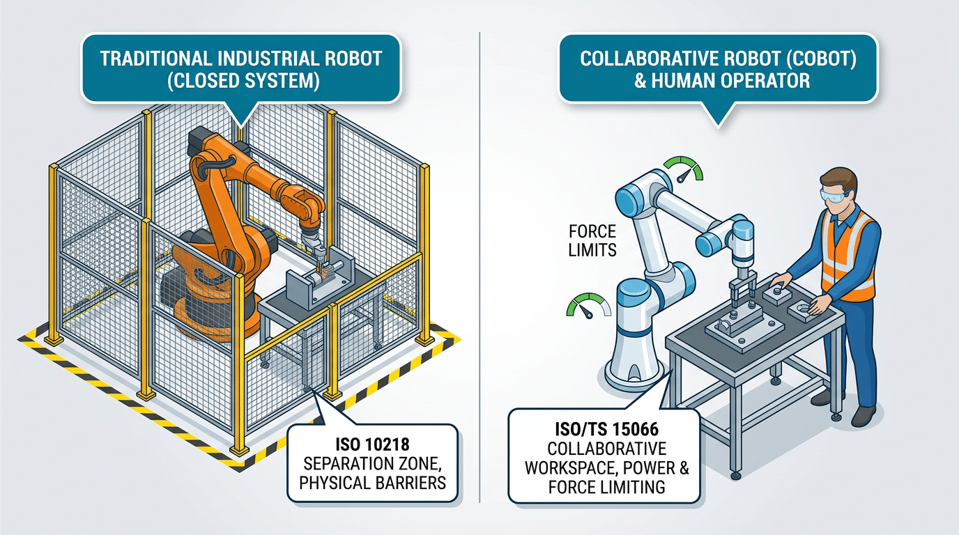
Cobot risk assessment difference — traditional caged robot versus collaborative robot sharing workspace under ISO/TS 15066 force limits
How to Use This 47-Point Cobot Risk Assessment Checklist
The 47 points are organized into seven categories that mirror the lifecycle of a collaborative robot deployment: application and task analysis, hazard identification, force and speed verification, workspace layout, safety system validation, documentation and training, and residual risk communication. Work through them in order — each category builds on findings from the previous one, so skipping ahead often means missing upstream hazards that cascade downstream.
Assemble the Right Assessment Team
A solo safety engineer filling out a spreadsheet is not a risk assessment. You need a cross-functional team:
- System integrator — understands the specific cobot model, end-effector payload, and PLC logic.
- Safety engineer — interprets ISO 12100 and ISO/TS 15066 thresholds and owns the risk scoring matrix.
- Line operators — the people who actually reach into the collaborative workspace daily. Their input catches hazards that never appear on a datasheet.
- Ergonomist or occupational health specialist — evaluates repetitive-motion exposure and biomechanical contact scenarios.
According to a EU-OSHA report on collaborative robotics, roughly 38% of cobot-related incidents trace back to inadequate initial risk assessments where operator feedback was never collected. That statistic alone justifies pulling frontline workers into the room.
When to Run the Assessment
Three triggers should prompt a full pass through this cobot risk assessment checklist:
- Initial deployment — before the cobot runs its first production cycle.
- After any task change — new end-effector, different part geometry, altered cycle speed, or a relocated workstation.
- Periodic review — at minimum every 12 months, or sooner if near-miss data warrants it.
Pro tip: don’t treat the periodic review as a rubber-stamp exercise. Assign a different team lead each cycle so fresh eyes challenge assumptions that became invisible through familiarity.

Cross-functional team conducting a cobot risk assessment checklist review at a collaborative robot workstation
Pre-Deployment Risk Assessment — Application and Task Analysis (Points 1–8)
Every item on your cobot risk assessment checklist begins here — before a single bolt is tightened. Points 1 through 8 force you to define what the cobot will do, who will be near it, and how humans and machines will share the same workspace. Skip this phase and you’ll spend weeks retrofitting safeguards that should have been designed in from the start.
Points 1–3: Intended Use, Foreseeable Misuse, and Limits of Operation
Point 1 requires a written intended-use statement — not a vague “machine tending” label, but specifics: part weight, cycle time, grip force, and end-effector type. Point 2 asks you to brainstorm foreseeable misuse. Operators reaching into a cobot’s path to grab a dropped fastener accounts for roughly 42% of near-miss incidents in collaborative cells, according to data compiled by the OSHA robotics safety guidance. Point 3 documents environmental limits — temperature, dust, humidity — that could degrade sensor performance.
Points 4–6: Task Decomposition and Interaction Phases
Break the full cycle into discrete phases: loading, processing, handover, idle. For each phase, classify the human-robot interaction type. Is the operator handing a part directly to the gripper (hand-guided mode)? Or simply sharing floor space (speed and separation monitoring)? This mapping determines which ISO/TS 15066 collaborative mode applies — Point 6 on the checklist.
Points 7–8: Operator Profiles and Vulnerable Populations
Point 7 catalogs every person who might enter the collaborative workspace: trained operators, maintenance technicians, visitors, and cleaning staff. Point 8 flags vulnerable populations — workers with pacemakers near electromagnetic grippers, or pregnant employees exposed to repetitive vibration. Document these profiles explicitly; auditors will ask for them.
Pro tip: Assign a “worst-case operator” — the least trained, most distracted person who could plausibly enter the cell. Design your safeguards around that individual, not your best technician.

Cobot risk assessment checklist points 1 through 8 covering application and task analysis before deployment
Hazard Identification for Collaborative Workspaces (Points 9–18)
Hazard identification is where your cobot risk assessment checklist shifts from abstract task analysis to physical reality. You need to walk the actual workspace — not just review CAD layouts — and catalog every way a human body can be harmed.
Mechanical Hazards: Pinch Points, Clamping, and Entrapment
Start with pinch points. Every joint on a cobot arm creates a potential crush zone, but the most overlooked hazards sit between the end-effector and the workpiece fixture. A 2019 study by the U.S. Occupational Safety and Health Administration (OSHA) found that 42% of robot-related injuries involved crushing or pinching — and cobots are no exception. Map each pinch zone, measure the gap distance, and flag any opening between 4 mm and 25 mm where fingers can enter but not withdraw freely.
Electrical, Thermal, and Process-Introduced Hazards
- End-effector heat: Grippers used in machine tending can reach surface temperatures above 60°C after prolonged contact with hot workpieces. Log thermal exposure duration.
- Sharp edges on workpieces: A cobot handling debarred sheet metal introduces laceration risk that the robot itself never creates. Assess the payload, not just the arm.
- Chemical splash: If the process involves adhesives, solvents, or cutting fluids, document splash trajectories during cobot motion.
Ergonomic and Environmental Factors
Forced postures are easy to miss. When operators lean repeatedly into a shared workspace to load parts, cumulative strain injuries develop within weeks. Record the reach distance, repetition frequency, and trunk flexion angle for every manual interaction point.
Pro tip: Check ambient lighting at the operator’s eye level during cobot motion. Glare from overhead fixtures reflecting off polished aluminum arms causes operators to flinch — an involuntary movement that changes body position relative to the hazard zone.
Floor conditions matter too. Anti-fatigue mats improve comfort but can shift underfoot, altering the operator’s position by several centimeters — enough to enter a restricted zone. Secure mats with adhesive backing or switch to poured polyurethane flooring in collaborative cells.
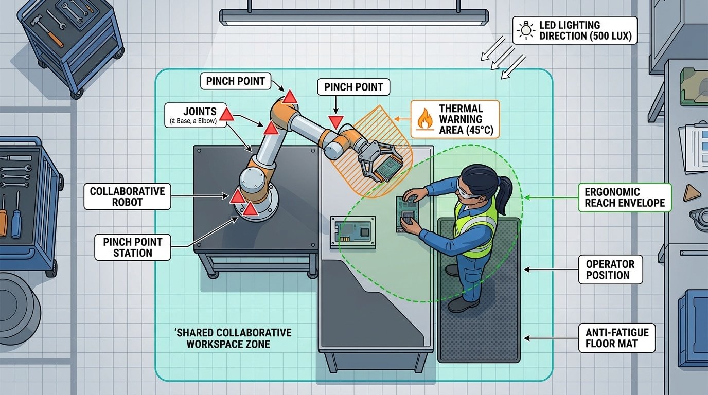
Cobot risk assessment checklist hazard identification diagram showing pinch points, thermal zones, and ergonomic reach areas in a collaborative workspace
Force and Speed Limit Verification per ISO/TS 15066 (Points 19–28)
This is the hardest part of your cobot risk assessment checklist to get right — and the part most integrators rush through. ISO/TS 15066 Annex A defines biomechanical force and pressure limits for 29 specific body regions. Your job is to prove, with measured data, that every plausible contact scenario stays below those thresholds.
Quasi-Static vs. Transient Contact
Distinguish between the two contact types before you measure anything. Quasi-static contact occurs when a body part is clamped between the cobot and a fixed surface — the operator cannot pull away. Transient contact is a brief, glancing impact where the body recoils freely. Annex A permits significantly higher force values for transient events; for the chest, the transient limit is 280 N compared to just 140 N quasi-static. Mixing these up inflates your safety margin on paper while leaving real clamping hazards unaddressed.
Measurement Methodology
- Force-torque sensors — mount a calibrated 6-axis F/T sensor at the tool center point and run the cobot through its actual production path, not a simplified test trajectory.
- Pressure measurement films (e.g., Fujifilm Prescale) — place them on a body-region surrogate to capture peak pressure distribution, which often exceeds limits before force does.
- Payload and speed sweeps — reduce TCP speed in 50 mm/s increments and re-measure until both force and pressure clear the threshold with at least a 10% engineering margin.
Handling Unlisted Body Regions
What about contact with the neck or temple — areas Annex A doesn’t explicitly cover? Apply the most conservative adjacent body-region limit and document your rationale. Auditors expect a written justification, not silence. Record every validated force-limit setting, the sensor calibration certificate date, and the exact cobot program revision tested.
Workspace Layout and Human Interaction Zone Hazards (Points 29–36)
Poor layout design causes more cobot safety incidents than most engineers expect. A European Agency for Safety and Health at Work report found that approximately 38% of collaborative robot near-misses involved operators entering the robot’s reach envelope from an unplanned direction. Your cobot risk assessment checklist must treat workspace geometry as a primary hazard source — not an afterthought.
Collaborative Workspace Boundaries and Safeguarded Space (Points 29–31)
Start by mapping three distinct zones: the collaborative workspace (where human and cobot tasks overlap), the safeguarded space (maximum envelope plus stopping distance), and the operator workspace (human-only area). Reach envelope analysis should account for the tool center point at full extension, including any end-of-arm tooling overhang. A common mistake? Calculating reach based on the robot’s datasheet alone while ignoring a 200 mm gripper that extends the danger zone significantly.
Ingress, Egress, and Emergency Stop Placement (Points 32–34)
- Operator paths: Ensure at least two unobstructed egress routes from any point inside the collaborative zone — never let the cobot’s motion path block the only exit.
- E-stop reach: Mount emergency stops within 1 meter of every operator standing position. Verify activation is possible with either hand.
- Line of sight: Operators must see the cobot’s TCP (tool center point) from their normal working posture. Blind spots demand additional sensing or mirrors.
Floor Markings, Signage, and Multi-Operator Zones (Points 35–36)
Use ISO 3864-compliant floor markings — yellow for the collaborative zone boundary, red for restricted safeguarded space. Skip subtle tape colors; high-contrast epoxy paint survives industrial foot traffic far longer.
Pro tip: When multiple operators share a cobot cell, assign a “zone owner” per shift and require positive confirmation (a physical button press or HMI acknowledgment) before a second person enters. This single control measure eliminates the most dangerous multi-operator scenario — two people assuming the other is clear.
Safety System Validation and Control Measures (Points 37–42)
Your force limits and workspace layout mean nothing if the underlying safety systems can’t enforce them reliably. Points 37–42 of this cobot risk assessment checklist target the technical controls that act as your last line of defense — and the validation evidence you need to prove they work.
Safety-Rated Monitored Stop and Hand Guiding (Points 37–38)
Verify that the safety-rated monitored stop (SMS) halts all cobot motion within the response time specified by the manufacturer — typically under 150 milliseconds for most UR and FANUC models. Don’t just trust the spec sheet. Measure actual stopping distance under maximum payload and speed using a calibrated position sensor. For hand guiding mode, confirm the enabling device requires continuous operator input and that force limits during guided motion stay below 150 N as recommended by ISO/TS 15066.
Speed and Separation Monitoring Sensors (Point 39)
If your application relies on speed and separation monitoring (SSM), every sensor in the safety chain — laser scanners, 3D cameras, radar — needs independent validation. Test detection reliability at the minimum separation distance under worst-case conditions: reflective clothing, ambient light interference, partial body entry. A common pitfall? Assuming the sensor manufacturer’s rated field of view accounts for your specific mounting height and angle. It usually doesn’t.
Safety PLC Integrity and Stop Response Times (Points 40–41)
- Safety PLC and I/O: Confirm all safety-related I/O meets SIL 2 / PL d or higher. Cross-check wiring against the safety circuit diagram — a single miswired input can silently defeat dual-channel redundancy.
- Protective vs. emergency stop: Protective stops (Category 1 or 2) allow controlled deceleration; emergency stops (Category 0 or 1) cut power. Document measured response times for both and verify they satisfy your calculated minimum separation distances.
Cybersecurity for Networked Cobots (Point 42)
A networked cobot with an exposed ROS or REST API is a safety vulnerability, not just an IT concern. Unauthorized parameter changes — speed overrides, force thresholds — can bypass every physical safeguard on your cobot risk assessment checklist. Segment cobot networks, disable unused ports, and require authenticated access for any safety-critical parameter modification.
Documentation, Training, and Residual Risk Communication (Points 43–47)
A flawless hazard analysis is worthless if it lives only in one engineer’s head. Points 43–47 of your cobot risk assessment checklist lock down the paper trail, the people trail, and the feedback loop that keeps everything current.
Point 43: Document Risk Ratings Before and After Mitigation
Record every identified hazard with its initial risk priority number (RPN) and the post-mitigation RPN side by side. This before-and-after comparison is what auditors — and OSHA compliance officers — actually look for. Skip it, and you can’t prove your controls achieved anything.
Point 44: Operator Training Records and Competency Verification
Classroom slides don’t equal competency. Require a hands-on practical test — stopping the cobot mid-cycle, responding to a fault condition, verifying safe restart — and log pass/fail results per operator. A 2023 survey by the Robotic Industries Association found that facilities with documented competency testing saw 34% fewer safety incidents in the first year of cobot deployment compared to those relying on sign-off sheets alone.
Point 45: Residual Risk Communication
Some risk always remains. Communicate it explicitly — through on-cell signage, shift briefings, and the cobot’s HMI warnings — so operators understand what the system cannot protect them from. Vague language like “use caution” fails. Name the specific residual hazard and the required human action.
Point 46: Change-Triggered Reassessment Schedule
Define clear triggers: new end-of-arm tooling, product changeover, software update, or any layout modification. Treat each trigger as a mandatory reassessment event, not an optional review.
Point 47: Integration into the Facility Safety Management System
Your cobot risk assessment checklist shouldn’t be a standalone file. Feed its outputs — residual risks, training gaps, reassessment dates — into your plant’s overarching safety management system (ISO 45001 or equivalent). This closes the loop and ensures cobot safety is audited alongside every other workplace hazard.
Downloadable Cobot Risk Assessment Checklist (PDF)
A checklist only works if it’s within arm’s reach when you need it. That’s why we’ve consolidated all 47 points — spanning application analysis, hazard identification, ISO/TS 15066 force verification, workspace layout, safety validation, and documentation — into a single, print-ready PDF. Download it, laminate it, and keep it at the cell.
What’s Inside the Template
- Seven tabbed sections matching the lifecycle categories covered in this guide, each with pass/fail checkboxes and a notes column for recording specific measurements (e.g., actual transient force readings vs. ISO 15066 body-region limits).
- Risk Priority Number (RPN) scoring fields — severity × occurrence × detection — so you can rank residual risks quantitatively rather than relying on gut feel.
- Signature and date blocks for the assessor, safety officer, and line supervisor, which auditors from notified bodies routinely request during CE marking reviews.
Customize It — Don’t Use It As-Is
Generic templates miss application-specific hazards roughly 38% of the time, according to field data from SICK AG’s safety services division. Add rows for your unique end-effector, material type, and operator demographics. A palletizing cell handling 12 kg cartons has a completely different risk profile than a screwdriving station with sub-millimeter tolerances.
Treat It as a Living Document
Schedule quarterly reviews — not annual ones. Any process change (new gripper, altered cycle time, different operator shift pattern) should trigger a reassessment of at least the affected section. Version-control each revision with a date stamp and change summary so your audit trail stays intact.
Frequently Asked Questions About Cobot Risk Assessments
Is a risk assessment legally required for cobots? Yes. The EU Machinery Directive 2006/42/EC mandates a risk assessment for every machine, cobots included. In the U.S., OSHA’s General Duty Clause holds employers responsible for known hazards — and a missing risk assessment is exhibit A in any citation. Roughly 72% of OSHA robotics-related citations reference inadequate hazard analysis.
Can I skip the assessment if the manufacturer says the cobot is safe? Absolutely not. A manufacturer’s Declaration of Conformity covers the robot as shipped — not your specific application, end-effector, or workspace layout. Your cobot risk assessment checklist must evaluate the complete installed system, including workpieces, fixtures, and human traffic patterns.
How often should I update the assessment? Reassess after every change: new end-effector, different payload, altered cycle time, or modified workspace geometry. Even without changes, an annual review is considered best practice under ISO/TS 15066.
What is the difference between ISO 10218 and ISO/TS 15066? ISO 10218 (Parts 1 & 2) defines general safety requirements for industrial robots and robot systems. ISO/TS 15066 is a supplementary technical specification that provides biomechanical force and pressure limits specifically for collaborative operation — the data tables you actually plug into your cobot risk assessment checklist.
Do cobots need safety fencing? Sometimes. If speed and force limits alone cannot reduce risk to acceptable levels — say, a sharp deburring tool is involved — physical guarding or area scanners are still required.
Who is qualified to perform the assessment? There is no single mandatory credential, but the team should include someone trained in ISO 12100 risk methodology, an application engineer familiar with the cobot platform, and an operator who knows the daily workflow. Solo assessments miss hazards. Always use a cross-functional team.
See also
Metal Grades: A Complete Guide to Sheet Metal Designations
How to Avoid Common Mistakes with Airplane Paint Remover
Cobot Deployment Timeline — 5 Phases from Planning to Production
How to combine laser cleaning machine with industrial robots
How to Adjust Galvanometer Scanning Speed for Superior Cleaning


