

7 Types of Cobot Grippers Explained With Real Use Cases
The seven buyer-facing families are two-finger parallel, three-finger adaptive, vacuum, soft, magnetic, pneumatic and electric grippers. They are useful shopping categories, not seven mutually exclusive mechanisms. Jaw geometry, gripping principle and actuation must be selected together around the actual workpiece.
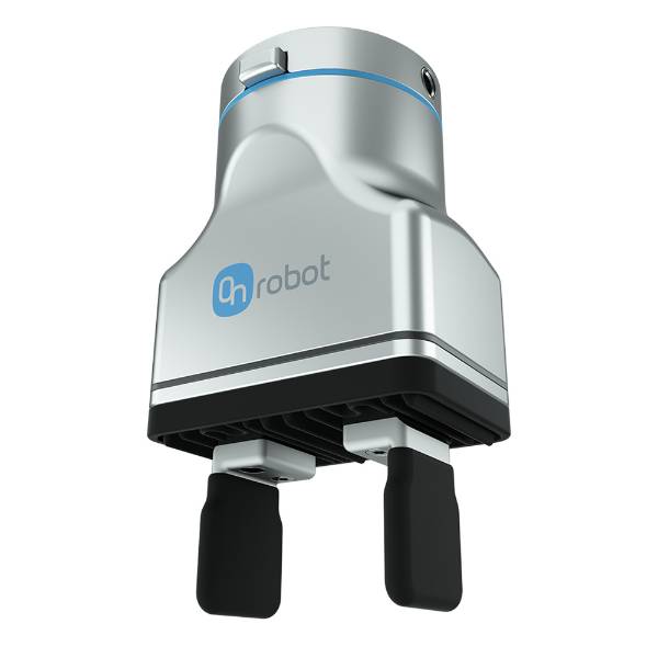
Start with the part—not the gripper catalogue.
A cobot gripper is the end-of-arm tooling that makes contact with the workpiece. The right type must retain the heaviest part during the fastest credible motion, fit inside the available approach space, tolerate the surface and environment, release reliably, and support the cell’s risk-reduction strategy. A strong bench test uses the worst part, lowest expected friction, highest acceleration, longest finger, most difficult orientation and realistic contamination.
Programmable stroke and force make it a practical first shortlist for machine tending, assembly and mixed prismatic parts.
Vacuum suits sealable surfaces; magnetic gripping suits compatible ferromagnetic parts, including perforated or dusty sheet.
Conforming fingers can widen the shape window and reduce localized contact pressure, subject to payload and cycle-time limits.
The robot, gripper, part, process tool, fixture and human interaction determine safety and production performance together.
From workpiece to validated EOAT
“Gripper type” can describe three different design decisions.
A parallel gripper can be electric or pneumatic. A vacuum gripper can use compressed-air ejectors or an electric pump. A three-finger gripper can be rigid and centric or underactuated and adaptive. Therefore, a useful specification separates the contact principle, finger geometry and actuator instead of treating every label as an alternative to every other label.
Gripping principle
Friction, form fit, vacuum pressure differential, magnetism or compliant enclosure determine how the tool creates and retains contact.
Contact geometry
Two-jaw, three-jaw, angular, internal-expanding, cup array, foam pad or soft finger geometry determines access and part support.
Actuation and control
Electric, pneumatic or passive mechanisms determine utilities, programmability, sensing, speed, failure behavior and integration effort.
Engineering rule: do not specify “an electric gripper” and stop. State the required grip mode, finger stroke, usable force range, speed, sensing, part-present confirmation, release behavior, environmental rating, tool mass, center of gravity and communication interface.
Use this table to build a shortlist—not to approve a purchase.
| Buyer-facing family | Best starting geometry | Primary advantage | Main limitation | Utilities / control | Typical starting applications |
|---|---|---|---|---|---|
| Two-finger parallelExternal or internal grip | Prismatic, cylindrical with shaped fingers | Simple, compact and widely supported | Needs suitable opposing contact surfaces | Electric or pneumatic | CNC tending, assembly, inspection |
| Three-finger adaptiveCentric or conforming grip | Round, irregular and mixed geometry | Self-centering and broad shape coverage | More mass, cost and clearance | Usually electric; model dependent | Lathe tending, labs, high-mix handling |
| VacuumCups, foam or area gripper | Flat or accessible sealable surface | Fast contact with no side access required | Leakage, porosity and surface condition matter | Air ejector or electric vacuum | Packaging, sheet, glass, palletizing |
| Soft / compliantConforming fingers or cups | Fragile, irregular or variable products | Distributes contact and tolerates variation | Lower stiffness, payload and precision | Electric, pneumatic or passive | Food, cosmetics, delicate packaging |
| MagneticContact pole surface | Compatible ferromagnetic parts | Works on perforated, dusty or oily steel | Material-specific; residual effects must be checked | Electromagnetic or electropermanent | Press brake, stamping, steel tending |
| PneumaticAn actuation layer | Depends on jaw or vacuum geometry | Compact, fast and mature hardware | Needs conditioned air and valve logic | Compressed air plus I/O or fieldbus | High-cycle tending, molding, assembly |
| ElectricAn actuation layer | Depends on finger architecture | Programmable force, stroke, speed and feedback | Model-specific force, duty and protection limits | Power plus digital or fieldbus control | High-mix work, traceable assembly, flexible cells |
Actual payload, force, stroke, cycle time, ingress protection, cleanroom suitability and failure behavior are product-specific. Validate values against the current manufacturer manual and the complete application.
What each family does well—and where it fails.
Two-finger parallel grippers
Two jaws move toward or away from one another along a parallel path. They can clamp the outside of a part, expand into an internal feature, or use shaped fingertips to create a form fit. Symmetrical motion can center a workpiece, which is valuable for loading chucks, fixtures and inspection stations.
Parallel grippers are popular because the mechanics are understandable and custom fingers are relatively easy to machine or print for trials. Their apparent simplicity can hide important details: long fingers reduce usable gripping capability, off-center parts increase moment loads, and smooth or contaminated surfaces can reduce friction.
- Choose flat pads for consistent prismatic parts.
- Use V-grooves or contoured fingers for round stock.
- Prefer form-fit capture when possible instead of relying only on friction.
- Confirm that open fingers clear fixtures and machine doors.
Three-finger adaptive or centric grippers
Three contact points can self-center round parts and stabilize geometries that are awkward for two opposing jaws. A rigid centric mechanism moves all jaws together; an underactuated adaptive design allows finger segments to conform around a workpiece with fewer actuators than joints.
This flexibility is useful in high-mix production, but it is not free. The tool may be heavier, wider and slower than a simple two-jaw device. Its fingers can also create more pinch points and require greater approach clearance. For precision loading, ask whether the gripper repeats the part center accurately enough for the downstream fixture—not merely whether it can hold the part.
- Useful for cylindrical stock, castings and mixed part families.
- Can reduce finger changes when size and shape vary.
- Grip modes and contact sequence must be validated for every SKU.
- Round-part centering does not replace a fixture datum.
Vacuum grippers
Vacuum gripping creates a pressure differential across a cup, foam pad or area gripper. It is attractive when the robot can access only one face of a box, sheet or panel. Multiple cups can distribute load and resist peeling moments, while independent zones can support double picks or mixed package sizes.
Holding capability depends on effective sealed area and achievable vacuum, then must be derated for acceleration, orientation, leakage, wear and uneven load sharing. Porous cardboard, textured surfaces, dust, oil, holes and flexible sheet can all change the result. A vacuum switch should confirm grip; do not treat pump-on as proof that the part is attached.
- Cups suit defined pickup points on smooth surfaces.
- Foam and area grippers can tolerate porosity and variable footprints.
- Electric vacuum reduces air infrastructure; ejectors can be compact and fast.
- Design for cup inspection, filter service and controlled loss-of-vacuum response.
Soft and compliant grippers
Soft fingers, flexible cups and compliant mechanisms conform to the part rather than forcing every item into a rigid jaw geometry. The larger contact area can lower localized pressure and accommodate natural variation in food, consumer products and delicate packages.
Compliance improves tolerance to shape variation but reduces stiffness. That can make precise insertion, high acceleration and tightly controlled orientation more difficult. “Food grade,” washdown capability, chemical resistance and hygienic design are also distinct requirements; verify the exact material, certification and cleaning procedure for the supplied configuration.
- Start with the permitted deformation and surface-marking limit.
- Test wet, dry, cold, warm and contaminated product states where relevant.
- Measure product damage, not only successful picks.
- Verify fatigue life and replacement interval of compliant elements.
Magnetic grippers
Magnetic grippers can pick compatible ferromagnetic parts without enclosing the sides or creating an airtight seal. This makes them valuable for perforated, dusty, oily or uneven steel parts that challenge vacuum cups. Adjustable magnetic force and part detection can also help separate thin sheets.
Material identity matters. Many steels are magnetic, while aluminum, copper and most austenitic stainless steels are not suitable. Available holding force changes with air gaps, coating, surface roughness, part thickness and contact area. Electropermanent designs can maintain holding force without continuous power, but the exact failure behavior must be confirmed from the product documentation.
- Check actual alloy response—not the generic label “metal.”
- Test single-sheet separation at minimum and maximum stack height.
- Assess residual magnetism and downstream process sensitivity.
- Keep chips from creating unintended air gaps at the pole face.
Pneumatic grippers
Pneumatic is an actuation method rather than a contact geometry. Compressed air can drive parallel jaws, angular jaws, centric grippers, soft fingers or vacuum ejectors. Pneumatic devices are mature, compact and capable of fast binary motion, especially in plants that already maintain clean, dry compressed air.
The complete cycle includes valve switching, hose fill and exhaust, sensor response and controller logic—not only the jaw’s catalogue motion time. Grip force varies with pressure and mechanism. Pressure loss, broken tubing and valve faults must have a defined safe response, particularly for vertical or overhead handling.
- Document operating pressure and air-quality requirement.
- Use position or part-present sensing where a missed pick matters.
- Include valve and hose dynamics in the cycle-time trial.
- Plan for seal, filter and tubing inspection.
Electric grippers
Electric is also an actuation layer. Servo or stepper-driven grippers can offer programmable position, speed and grip-force settings, along with status feedback. This makes them attractive for high-mix cells in which one tool must handle several products or where the controller needs evidence that an object interrupted the commanded stroke.
Feedback semantics differ by product. Some devices infer object detection from position and motor current rather than measuring fingertip force directly. Force settings, resolution, repeatability, duty cycle and ingress protection must therefore be read from the model-specific manual. Do not assume every electric gripper is a force sensor.
- Use recipes for SKU-specific stroke, speed and force.
- Log position and object-detected status when traceability adds value.
- Verify network, I/O and cobot software compatibility.
- Check motor heating and permitted duty for the real cycle.
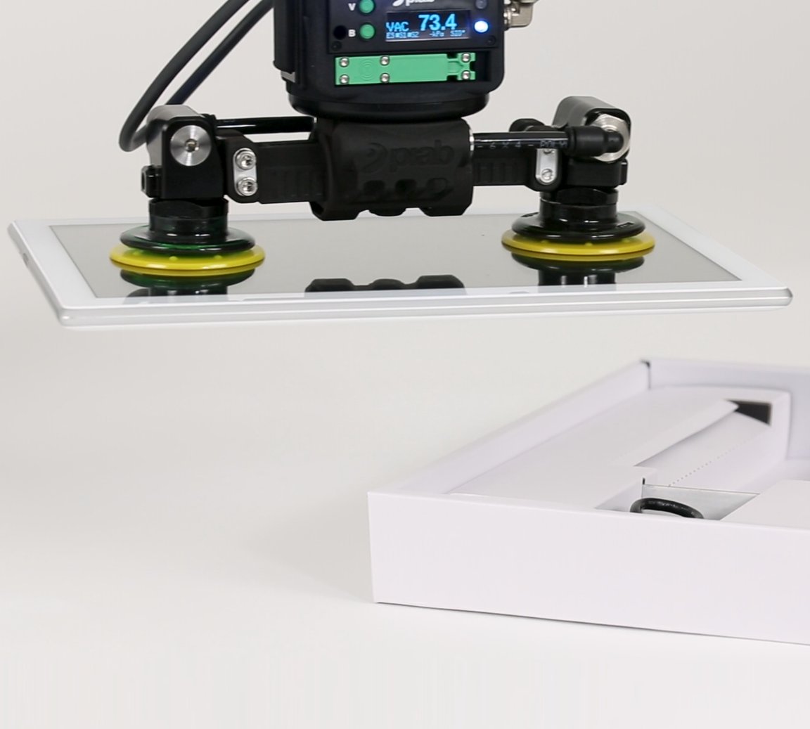
Vacuum gripping is a system of cups, flow, sensing and motion.
A cup that holds a stationary sample may still peel away during a fast horizontal move. The application must consider cup position relative to the part center of gravity, effective sealed area, available vacuum, leakage, acceleration and hose or pump response.
- Place cups to resist rotation and peeling, not merely to maximize area.
- Use a vacuum switch and a defined “grip achieved” threshold.
- Test worn cups and realistic dust or oil—not only new cups on a clean sample.
- Define what the robot does if vacuum decays during transfer.
Build a starting gripper route from the workpiece.
This tool suggests a concept for early planning. It does not size holding force, approve a collaborative application or replace a manufacturer review and representative trial.
Electric two-finger parallel gripper
Opposing faces and programmable stroke make this a versatile first concept. Determine whether friction grip is sufficient or a form-fit finger can capture the part more reliably.
Validate next: part tolerance, finger clearance, lowest friction, worst orientation, total tool mass, center of gravity and lost-grip response.
Discuss My Automation ApplicationA gripper that can hold the part can still overload the robot.
The robot carries more than the workpiece. Include the gripper, custom fingers, tool changer, adapters, sensors and any carried cables or hoses included by the robot manufacturer’s payload definition. After pickup, the workpiece shifts the combined center of gravity—often farther from the wrist, where allowable moments become more restrictive.
Universal Robots’ payload guidance explicitly treats active payload as gripper plus workpiece and shows that combined center of gravity must be recalculated, not merely the mass added. Robot-brand limits for payload, center of gravity, inertia and wrist torque must all be satisfied across the entire motion.
Do not use nominal arm payload as the permitted part weight. The real part allowance is what remains after all end-of-arm mass is included, subject to the robot’s center-of-gravity, moment and inertia limits.
Surface physics can eliminate entire gripper families.
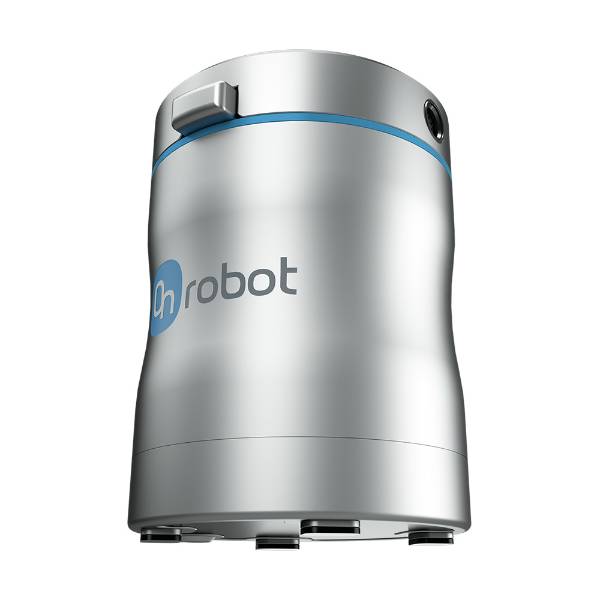
Magnetic: material-gated
Excellent access to compatible steel does not make it a universal “metal gripper.” Confirm alloy response, thickness, coating, pole contact and downstream sensitivity.
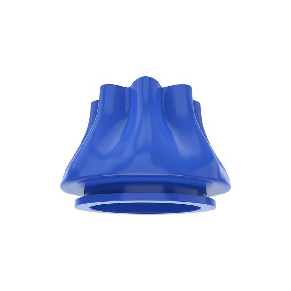
Soft: product-gated
Gentle contact is valuable only if the tool also meets stiffness, hygiene, temperature, fatigue, cycle-time and release requirements.
Match the gripper to the difficult moment in the cycle.
The hardest action may not be pickup. A part can be easy to lift but difficult to insert, rotate, present to a scanner, load through a narrow machine opening or retain during an emergency stop. Review the full sequence before selecting the EOAT.
CNC & press work
- Two-finger for defined billets and fixtures
- Three-finger for round lathe stock
- Magnetic for compatible steel sheet
- Check coolant, chips and door clearance
Boxes, bags & trays
- Vacuum for accessible top surfaces
- Foam area grip for porosity
- Soft grip for deformable products
- Test double picks and damaged cartons
Insertion & kitting
- Electric force/stroke recipes
- Form-fit fingers for orientation
- Part-present confirmation
- Coordinate gripper with vision and fixtures
Cleaning, welding & marking
- Fixture or gripper must preserve process datum
- Protect EOAT from heat, spatter, fumes and reflected light
- Manage cables, hoses and extraction
- Laser safeguards apply to the complete cell
The gripper, part and process can change the safety concept.
A cobot arm with safety functions does not automatically make the completed application safe for contact. OSHA’s robotics guidance directs evaluation of the complete robot application, including the end-effector and workpiece. ISO 10218-1:2025 addresses industrial robots, while ISO 10218-2:2025 addresses industrial robot applications and cells. ISO/TR 20218-1 provides additional end-effector safety guidance, and ISO/TS 15066 remains a reference for collaborative applications while revision work is underway.
Sharp custom fingers, exposed pinch points, a heavy workpiece, a hot casting, a welding torch or a Class 4 laser process may require guarding, monitored separation, interlocks or other measures even when the arm itself is marketed as collaborative.
Validate with a representative part family and a fault plan.
1. Define the workpiece envelope
- Minimum and maximum mass, dimensions and tolerance
- Surface roughness, coating, oil, dust, porosity and temperature
- Permitted marks, deformation and contamination
- Center of gravity and required orientation
2. Define the motion envelope
- Pickup and placement orientations
- Maximum acceleration and emergency behavior
- Approach clearance, machine opening and fixture interference
- Cable, hose and tool-changer routing
3. Prove grip and release
- Lowest expected friction or vacuum condition
- Longest fingers and worst off-center grip
- Part-present and lost-grip detection
- Consistent release without sticking or double picking
4. Prove production ownership
- Cycle time including valves, sensing and recovery
- Cleaning, inspection and preventive maintenance
- Spare fingers, cups, seals, filters and cables
- Approved recipes, training and change-control record
Factory acceptance should include degraded conditions. Test a worn cup, low air pressure, minimum-friction surface, maximum part tolerance, interrupted signal and controlled power loss. A cell is not robust if it works only with a clean sample and new tooling.
Plan the part, EOAT, fixture and laser system as one cell.
If your cobot project includes laser cleaning, laser welding or laser marking, Oceanplayer can review the part, access, process target and automation route. Share representative drawings, photos, material, cycle target and required result so the discussion starts with the real application.
Related automation and laser-system resources
Questions buyers ask about cobot grippers
Use these answers for early planning, then verify the selected model and complete application.
What are the seven main types of cobot grippers?
The seven useful buyer-facing families are two-finger parallel, three-finger adaptive, vacuum, soft or compliant, magnetic, pneumatic and electric grippers. These labels overlap: pneumatic and electric describe actuation, while parallel and three-finger describe geometry, and vacuum or magnetic describe the gripping principle.
What is the best all-purpose gripper for a first cobot project?
An electric two-finger gripper is often a practical first shortlist because stroke, speed and force settings can be changed for several prismatic parts. It is not universally best. Flat cartons may favor vacuum, round stock may favor three fingers, and delicate or ferromagnetic parts may favor specialist tools.
How do I calculate the payload available for a workpiece?
Start with the robot manufacturer’s active-payload definition. Include the gripper, fingers, tool changer, adapters, sensors and workpiece, then calculate the combined center of gravity. Confirm payload, center-of-gravity, moment and inertia limits for both empty and loaded states across the planned motion.
Is an electric gripper safer than a pneumatic gripper?
Not automatically. Programmable force and position feedback may help control some hazards, but safety depends on the complete end-effector, fingers, part, speed, failure behavior and human interaction. A risk assessment must evaluate the delivered application rather than the actuator label.
When should I choose vacuum instead of fingers?
Vacuum is attractive when only one broad surface is accessible or when side clamping would damage the part. Confirm sealability, effective area, leakage, porosity, peeling moment, cup wear, vacuum sensing and loss-of-vacuum response with representative parts.
Can a magnetic gripper handle every metal?
No. Magnetic gripping requires compatible ferromagnetic material. Aluminum, copper and most austenitic stainless steels are not suitable. Holding performance also depends on thickness, coating, surface condition, air gap, contact area and the specific magnetic technology.
Are soft grippers only for food?
No. Soft or compliant grippers can handle cosmetics, fragile packaging, laboratory items and irregular consumer products. Food-contact claims, hygiene, washdown, temperature and chemical resistance must be verified for the exact gripper material and configuration.
Can one cobot gripper handle multiple part types?
Yes, within a validated envelope. Programmable electric grippers, adaptive fingers, vacuum arrays and custom fingertips can widen the SKU range. If the geometries or processes conflict, a tool changer may be more reliable than forcing one gripper to do every task.
Do cobot grippers need force sensors?
Not every application needs a separate force sensor. Some electric grippers infer object detection from motor current and position, while others provide richer force feedback. Define what the cell must know—part present, jaw position, clamp force or insertion force—and select sensing accordingly.
How should custom fingers be designed?
Use the shortest practical fingers, support the part near its center of gravity, avoid sharp exposed geometry, maximize form fit where appropriate and check finger stress, deflection and collision clearance. Recalculate the tool center of gravity and repeat the application risk assessment after any finger change.
What should be tested before buying a cobot gripper?
Test the heaviest, lightest, smallest, largest, most fragile and most contaminated approved parts. Include the fastest motion, worst orientation, longest fingers, lowest air pressure or vacuum, worn contact elements, fault recovery and controlled power loss.
Does a collaborative gripper make the whole cell collaborative?
No. Collaborative operation is an application property. The end-effector, workpiece, fixtures, process energy, access and foreseeable contact must be included in the risk assessment. Welding, cutting or laser hazards can require enclosure and interlocks regardless of the cobot label.
Sources used to verify the engineering framework
- ISO 10218-1:2025 — Robotics — Safety requirements — Part 1: Industrial robots.
- ISO 10218-2:2025 — Robotics — Safety requirements — Part 2: Industrial robot applications and robot cells.
- ISO/TS 15066:2016 — Robots and robotic devices — Collaborative robots; ISO currently lists revision work in progress.
- ISO/TR 20218-1:2018 — Safety design for industrial robot system end-effectors.
- OSHA Technical Manual, Section IV, Chapter 4 — Industrial Robot Systems and Industrial Robot System Safety.
- Universal Robots — Payload and combined center-of-gravity guidance.
- Robotiq — Adaptive Grippers and its current product specifications.
- OnRobot — 2FG7 electric parallel gripper architecture and feedback features.
- OnRobot — VG10 electric vacuum gripper.
- OnRobot — MG10 magnetic gripper.
- Piab — piCOBOT vacuum gripper unit.
- SCHUNK — EGP gripper engineering notes on workpiece weight, force-fit gripping and cycle-time interpretation.
This guide supports early engineering and procurement planning. Product limits, applicable legislation, conformity duties and required safeguards depend on the exact equipment, country, workpiece and completed application.