

How to Laser Weld Highly Reflective Materials
Highly reflective metals can be laser welded, but the process window must be built around energy coupling and system protection—not raw laser power alone. Select a source and beam delivery system that match the alloy, thickness and joint; control surface condition and fit-up; stabilize the weld pool; and protect the laser from hazardous back-reflection.
Copper, aluminum, brass, gold-coated parts and dissimilar joints do not behave as one material family. Their reflectivity, thermal conductivity, volatile alloying elements, oxide films and metallurgical reactions create different risks. The practical route is a controlled test plan that connects wavelength, power density, travel speed, focus, beam shape, shielding and inspection to the actual part.
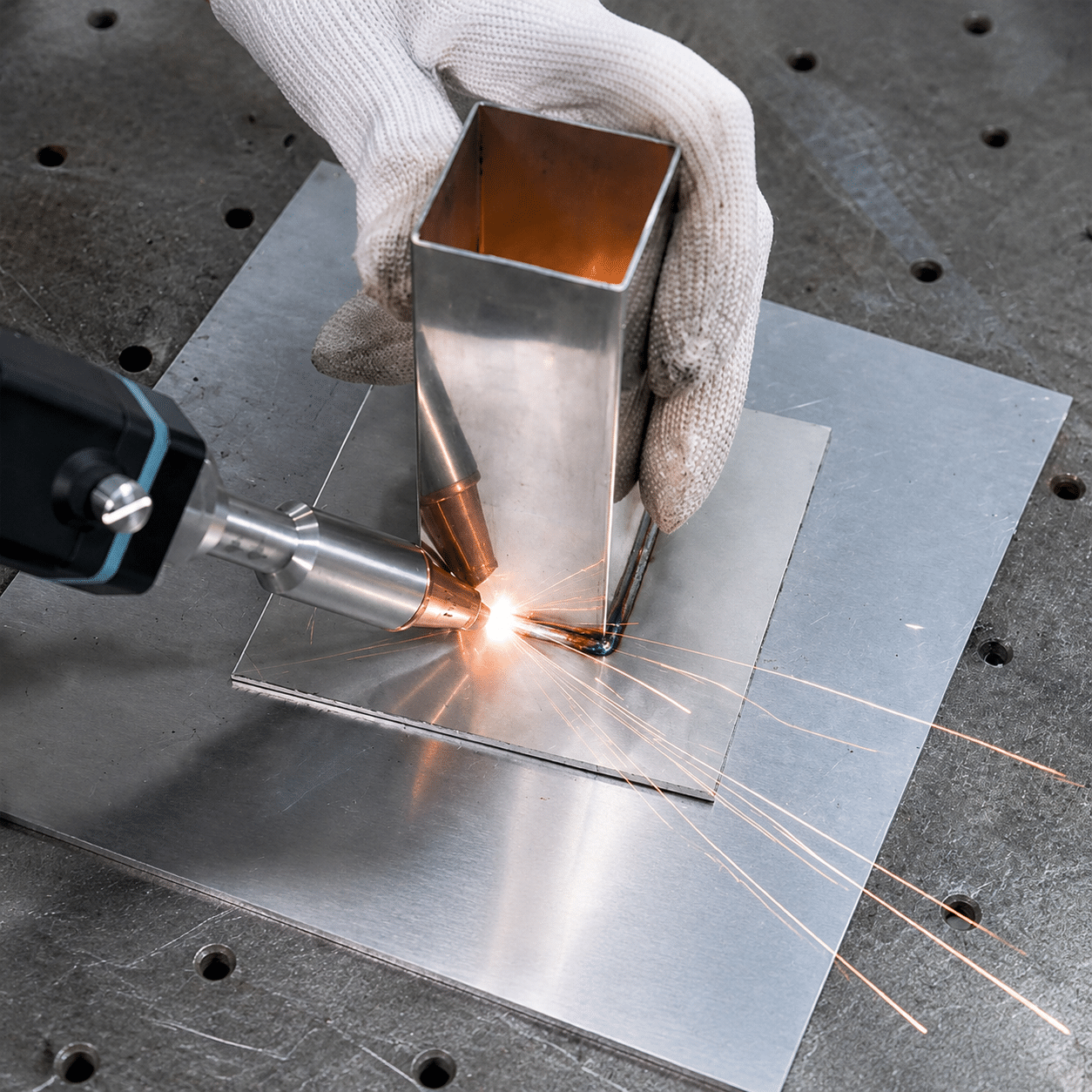
Treat reflectivity as a system variable.
Cold-surface reflectivity matters, but it is not the whole weld. Absorptivity changes as the surface heats, melts and transitions into a keyhole. A workable process therefore controls the entry into the weld, the steady-state pool and the way reflected energy is handled by the source and optics.
Infrared fiber, green and blue sources offer different power, beam-quality and cold-surface coupling trade-offs.
Reflection, rapid heat flow, oxide, contamination and poor fit-up can cause spatter, porosity or incomplete fusion.
Confirm the exact laser, process head, delivery fiber, monitoring and optical protection are approved for the application.
Validate the real alloy, coating, geometry and production tolerance with cross-sections and application-specific tests.
Why are highly reflective materials harder to laser weld?
For process planning, “highly reflective” describes a surface that initially returns a large portion of the incident wavelength instead of coupling it into heat. That raises the threshold for a stable melt or keyhole and creates a second problem: the reflected beam can return toward the process head and laser source.
A clean, polished copper surface can be particularly difficult for near-infrared light at the start of the process. Surface condition, temperature, phase and wavelength all influence the instantaneous absorption.
Copper and aluminum conduct heat efficiently. A small parameter change can shift the process between insufficient fusion, conduction-mode welding and an unstable keyhole.
The direction and magnitude of a return can change as the surface deforms and the pool develops. Equipment must be selected and configured for this load, not merely shielded by an improvised angle.
Room-temperature optical data can help compare wavelengths, but it cannot predict a production weld by itself. Surface roughness, oxide, coating, incidence angle, temperature, melting and keyhole geometry change the coupling during the weld. This is why fixed statements such as “copper reflects X percent” or “one wavelength is always best” are unreliable process specifications.
The difficult transition is often the beginning of the weld.
Before melting, limited absorption can make initiation sensitive to focus position, beam profile, surface condition and power ramp. Once a stable melt or keyhole forms, energy coupling usually changes. If initiation is inconsistent, operators may compensate with excessive power. The result can be a sudden transition from weak coupling to violent vaporization, spatter and keyhole collapse.
A better approach is to separate three process phases: start-up, steady travel and termination. Define ramping, approach motion and termination for each phase. Inspect the first and last portion of the seam rather than assuming a stable middle proves the complete cycle.
For repetitive production, monitor signals that can reveal a changing process: return light, plasma or thermal emission, laser power, head alarms, cover-glass condition and part-height variation. Monitoring does not replace metallographic validation, but it can help detect drift before a visible reject appears.

Choose the laser source by joint requirement, not color alone.
Source wavelength changes initial coupling, especially in copper, but a production choice also depends on available power, beam quality, spot size, delivery architecture, process-head compatibility, back-reflection rating, duty cycle, service support and total cost.
| Source route | Where it can be strong | Main limitation to verify | Good first questions |
|---|---|---|---|
| Near-infrared fiber laser approximately 1030–1080 nm | Widely available at high power; mature industrial ecosystem; commonly used for aluminum, steel and many mixed production programs. Copper can also be welded when intensity, beam delivery, start strategy and source protection are suitable. | Cold copper coupling is lower and more surface-sensitive than at visible wavelengths. A reflected load can be severe if the system is not designed for it. | Is the exact source approved for copper? What return-light protection and monitoring are built in? Can the beam profile or wobble be optimized? |
| Green laser around 515 nm | Higher initial absorption in copper can reduce the threshold for stable melting and support controlled conduction or keyhole welding. Peer-reviewed comparisons have shown improved coupling and stability in tested copper conditions. | Available power, beam quality, efficiency, integration options and cost differ by supplier. Results from one thickness or mode cannot be transferred blindly. | Is the required penetration achievable at production speed? What spot, working distance and scan strategy are available? |
| Blue laser around 445–450 nm | Strong visible-light coupling in copper and other nonferrous metals can support stable heating, thin-sheet joining, battery connections and additive energy delivery. | Power density and beam quality of the actual package may limit deep penetration. Joint access and optical integration still matter. | Is the task conduction-mode or keyhole welding? Does the available source deliver the required spot and brightness? |
| Hybrid or multi-beam approach | A visible source may establish controlled heating while an infrared source supplies penetration; shaped or multiple beams may widen the process window. | More hardware, alignment, control and validation complexity. Benefits must be demonstrated on the production joint. | Does the quality gain justify integration cost? How will both sources be monitored and serviced? |
Required power depends on wavelength, beam profile, spot size, thickness, joint geometry, speed, mode and material condition. A thin copper tab may need a controlled visible-light conduction weld; a thick busbar may require a high-brightness keyhole process. Power without stable coupling can increase spatter and equipment risk rather than improve the joint.
Build a first welding route for your application.
This planner organizes the first engineering conversation. It does not calculate a qualified welding procedure and should not be used as a machine setting sheet.
Describe the joint
Choose the closest combination. The planning recommendation updates immediately.
Compare visible and protected IR copper routes
For thin copper where stability is the priority, compare a green or blue visible-light route with a copper-approved infrared fiber system. Select by joint quality, throughput and integration—not wavelength alone.
Planning aid only. Final settings, guarding, PPE and acceptance tests must be defined by the responsible laser safety and welding personnel.
Back-reflection protection must be designed into the system.
A reflective workpiece can return energy into the process head, delivery fiber or laser source. The safe answer is not a generic promise that one isolator “blocks 99%.” Protection is equipment-specific and must be confirmed for the expected material, power, geometry and duty cycle.
Specify a compatible source.
Ask the laser manufacturer whether the exact model is approved for copper, aluminum or the planned reflective load. Review permitted return power, alarm behavior, shutdown logic and warranty conditions. A source used safely on steel is not automatically suitable for polished copper.
Protect and monitor the beam path.
Use the approved process head, protective windows, fiber interfaces and sensors. Monitor cover-glass contamination and return-light alarms. Define inspection and replacement intervals from process evidence rather than waiting for visible damage.
Control reflected-beam geometry.
Use manufacturer-approved head orientation, beam traps and enclosure surfaces. An uncontrolled workpiece tilt can shift the spot, alter penetration and redirect the hazard elsewhere. Geometry changes belong in the validated procedure.
If return-light, fiber, optics or temperature alarms occur, stop and identify the cause. Check material orientation, focus, head condition, cover glass, connector status and process stability. Repeated resets without root-cause review can turn a quality problem into an expensive source failure.
Control direct, reflected and airborne hazards.
High-power laser welding can expose people to hazardous direct, specular and diffuse optical radiation, hot material, fire, electrical energy and laser-generated airborne contaminants. Engineering controls are the first line of protection.

ISO 7010 W004 warning symbol: Maxxl2 / Wikimedia Commons, public domain.
Use a suitable protective enclosure, interlocks, controlled area, beam stops, warning systems and documented access procedures. Open Class 4 work requires a formal hazard assessment.
Ordinary welding shades are not automatically laser protective. Eyewear must match the actual wavelength and required optical density, and it does not replace enclosure or beam control.
Use source-capture extraction sized for the process. Brass can produce zinc-containing fume; plated or coated parts may introduce additional hazardous constituents. Identify coatings before welding.
Remove combustibles, manage spatter and hot parts, provide suitable fire response and follow the facility hot-work program. Reactive alloys and fine deposits may require specialized controls.
The laser safety officer or responsible safety professional must evaluate wavelength, power, exposure geometry, accessible emission, viewing conditions, enclosure, interlocks, ventilation and non-beam hazards. Training and standard operating procedures must match the actual cell.
Prepare the surface, joint and fixture as process variables.
High-reflective-metal welding is often blamed on “laser power” when the uncontrolled variable is contamination, oxide, plating, part height or gap. A repeatable preparation specification narrows the process window before parameter optimization begins.
Identify the exact material and condition.
Record alloy, temper, supplier, thickness and surface treatment. “Copper,” “aluminum” or “brass” is not enough. Electrical copper grades, anodized aluminum, die-cast aluminum and free-machining brass can present different gases, oxides and metallurgical risks.
Identify every coating and residue.
Confirm plating, oxide, lubricant, adhesive, paint and cleaning chemistry. Remove or manage them with a qualified method. Do not weld an unknown coating until its fumes, vaporization behavior and joint effect are understood.
Control fit-up and part height.
Measure gap, overlap, edge condition, flatness and fixture repeatability. Small gaps can change heat flow and filler demand. Height variation changes focus and, in scanner systems, can change spot size and energy density.
Verify preparation lifetime.
A clean surface can change during storage. Define the allowed time between cleaning and welding, handling rules, packaging and re-clean criteria. Use representative aged parts during validation if production will not weld immediately.
Establish shielding and extraction.
Choose gas and delivery according to alloy, joint and acceptance needs. Confirm flow at the weld rather than only at the regulator. Excessive flow can disturb the pool; poor placement can allow oxidation or fail to capture plume.
Lock a measurement baseline.
Record beam profile, focus reference, power at the workpiece, travel calibration, wobble pattern, wire delivery and optical condition. Without a baseline, a later “parameter change” may actually be equipment drift.

A good-looking copper weld may still fail the application.
For busbars, tabs and conductive assemblies, validate contact resistance or joint resistance, temperature rise, current-cycling behavior and mechanical integrity as required by the design. A broad, attractive bead does not prove low resistance; a narrow weld does not prove insufficient performance.
Fixture pressure, contact area, plating condition and weld location can influence both current path and heat flow. These factors should be represented in the test coupon. When the production component is layered, coated or thermally connected to a large heat sink, a flat single-sheet bead-on-plate test may provide misleading confidence.
Use cross-sections to connect the visible bead to penetration, porosity, interface fusion and heat-affected geometry. Then relate those observations to the functional test that matters to the product.
Build a window—not a single magic setting.
Each parameter changes more than one physical effect. Optimize with a designed sequence, record the result and change one controlled factor at a time unless using a formal design of experiments.
| Variable | What it changes | Too little / too low | Too much / too high | What to inspect |
|---|---|---|---|---|
| Power density | Heating rate, melt initiation and keyhole formation. | Intermittent melting, incomplete fusion, start failure. | Violent vaporization, spatter, undercut, excessive penetration or source stress. | Start consistency, penetration, plume behavior, return-light signal. |
| Travel speed | Energy per unit length and molten-pool residence time. | Excess heat, wider heat-affected zone, distortion, volatile-element loss. | Insufficient fusion, narrow unstable bead, start/stop sensitivity. | Cross-section, top/bottom bead, distortion and consistency over seam length. |
| Focus and spot size | Intensity, penetration shape and tolerance to height change. | A large spot may not reach the required threshold. | A very small intense spot may narrow the window and increase spatter. | Focus calibration, part height, optics condition and bead geometry. |
| Beam profile / wobble | Energy distribution, pool width, keyhole motion and gap bridging. | Insufficient interface coverage or unstable fusion. | Over-wide heating, reduced penetration or periodic defects if frequency/amplitude are mismatched. | Fusion width, periodicity, porosity, overlap and melt ejection. |
| Power ramp | Transition into and out of the weld. | Weak starts or crater-like termination. | Sudden absorption transition, spatter or local overheating. | First/last 10–20 mm, termination crater and monitoring signals. |
| Shielding gas | Oxidation, plume interaction and surface appearance. | Oxidation, contamination and inconsistent protection. | Pool disturbance or wasted flow; gas cannot compensate for poor extraction. | Flow at joint, nozzle position, discoloration and fume capture. |
| Filler wire | Gap tolerance, chemistry and molten volume. | Underfill, unbridged gap or unfavorable chemistry. | Cold wire, unstable transfer, excessive reinforcement or dilution change. | Wire aim, feed synchronization, alloy compatibility and cross-section. |
Statements such as “increase voltage” or “change to a metal-cored wire” are arc-welding advice, not universal laser-welding adjustments. A laser system may include a wire feeder, but the governing variables are laser power and beam delivery, motion, wire alloy/diameter/feed, joint geometry, shielding and the specific control architecture.
Use a different risk model for each reflective metal.
Material name is only the beginning. Alloy, temper, coating, thickness, joint and service requirement determine whether the first trial should prioritize coupling, vapor control, porosity, cracking, intermetallic formation or surface appearance.
Copper and copper alloys
Coupling + heat flowPure copper combines low cold-surface absorption at near-infrared wavelengths with high thermal conductivity. Visible green or blue sources can improve initial coupling; protected high-brightness infrared systems can also weld copper when the process window is appropriate.
- Separate pure copper from bronze, brass and precipitation-hardened copper alloys.
- Control surface condition and start strategy; cold-copper initiation can be sensitive.
- For electrical joints, validate resistance, thermal cycling and current load—not appearance alone.
- Watch for spatter, porosity, incomplete interface fusion and return-light alarms.
Aluminum alloys
Oxide + porosityAluminum is widely laser welded with infrared sources, but high thermal conductivity, surface oxide, hydrogen sources and alloy-dependent solidification behavior can reduce the quality window. Die castings and anodized layers require special attention.
- Identify wrought versus cast material and the exact series, temper and coating.
- Control oxide, lubricant, moisture and cleaning method.
- Use cross-sections or CT when porosity is critical; a smooth top bead can hide pores.
- Evaluate cracking susceptibility and filler selection for the actual alloy pair.
Brass
Zinc vapor + fumeBrass adds a volatile-element problem. Zinc can vaporize vigorously, disturb the keyhole, eject melt and create porosity while generating zinc-containing fume. Alloy identification and source-capture extraction are non-negotiable.
- Record zinc content and whether lead or other constituents are present.
- Test joint geometry and escape paths for vapor rather than hiding the plume.
- Use a controlled energy window that limits violent zinc loss while achieving fusion.
- Inspect below the attractive top bead; sub-surface porosity may be present.
Plated and dissimilar joints
Coating + metallurgyA thin reflective coating may dominate initial optical interaction while the substrate governs heat flow and joint strength. Dissimilar metals can also form brittle intermetallic phases or unfavorable dilution zones.
- Specify coating material, thickness, uniformity and condition.
- Model the heat sink and electrical path of the complete stack.
- Control penetration and dilution; “full mixing” may not be the best objective.
- Validate peel/shear/tensile, resistance, corrosion and thermal cycling as required.
Reactive alloys, combustible deposits and unknown coatings should not be grouped into a generic “reflective metal” recipe. Confirm composition, fire controls, fume hazards, enclosure compatibility and a qualified procedure before processing.
Use the defect pattern to choose the next controlled check.
The table below is a troubleshooting sequence, not a promise that one adjustment will correct every joint. Inspect the physical setup before changing several parameters.
| Observed result | Likely mechanisms to investigate | First controlled checks | Avoid this shortcut |
|---|---|---|---|
| Inconsistent start or intermittent fusion | Low or variable initial coupling, oxide/contamination, focus drift, part-height change, unstable ramp. | Verify surface preparation, power at workpiece, focus reference and start sequence. Compare monitoring traces across good and bad welds. | Do not jump to maximum power before confirming source compatibility and optical return. |
| Spatter or melt ejection | Abrupt keyhole transition, excessive local intensity, volatile coating/alloy element, unfavorable wobble, unstable fit-up. | Observe plume/pool behavior; review ramp, focus, speed, beam profile, coating and joint gap one variable at a time. | Do not assume slower travel always stabilizes the weld; it may increase vaporization. |
| Porosity | Hydrogen/moisture/oxide, coating vapor, keyhole collapse, gas entrapment, volatile zinc or magnesium. | Identify pore location and type with cross-section or CT; verify cleaning, storage, alloy, shielding, beam motion and escape path. | Do not judge porosity from the top bead alone. |
| Lack of penetration | Insufficient coupled intensity, large spot, high speed, focus error, heat sink, gap/stack error or poor interface contact. | Measure spot/focus and delivered power; verify stack and fixture; create a power-density/speed matrix. | Do not specify power without spot size, speed and joint geometry. |
| Cracking | Alloy solidification range, filler mismatch, restraint, dilution, thermal cycle or brittle intermetallics. | Identify crack location and phase; review alloy pair, filler, restraint, penetration and cooling with a welding/metallurgy specialist. | Do not apply universal preheat or slow-cooling advice without alloy-specific evidence. |
| Optics damage or return-light alarm | Unsafe reflection path, incompatible source/head, contaminated protective window, connector or fiber issue, unstable process. | Stop; follow manufacturer alarm procedure; inspect optics and geometry; review monitoring and source approval. | Never disable the alarm or repeatedly reset production without root-cause review. |
Validate the complete production envelope.
A successful bead on a hand-cleaned flat coupon is useful evidence, but it is not a production release. The validation plan must include the material and geometric variation the cell will actually see.
Build the test matrix
- Minimum, nominal and maximum material thickness.
- Supplier and alloy variation that purchasing will allow.
- Clean, aged and worst-acceptable surface condition.
- Minimum and maximum production gap, part height and fixture tolerance.
- Start, steady-state, corner/transition and termination regions.
- Nominal settings plus controlled upper and lower process limits.
Connect evidence to the product function.
Use visual and dimensional inspection, cross-sections and porosity assessment appropriate to the joint. Add leak, peel, shear, tensile, fatigue, corrosion, electrical resistance, thermal rise or pressure testing when the design requires it.
Document source model and wavelength, beam profile, delivered power, focus, head angle, wobble pattern, speed, wire, shielding, extraction, preparation, fixture and monitoring signals. The objective is to define a process window with detectability—not preserve one unexplained “golden setting.”
Material identity: alloy, temper, coating, thickness and supplier condition are known.
Optical compatibility: source, delivery fiber and process head are approved for the reflective load.
Safety controls: enclosure, interlocks, beam stops, PPE, extraction and procedures match the hazard assessment.
Process window: quality remains acceptable across defined input and fit-up limits.
Monitoring: alarms and process signals have documented action limits and response steps.
Functional evidence: the joint passes the mechanical, electrical, sealing or durability tests that matter.
Send the material, joint drawing and target result.
Oceanplayer can review your copper, aluminum, brass or dissimilar-metal application, define a representative sample-test plan and recommend a laser welding system direction based on quality, throughput, integration and safety requirements.
Laser welding highly reflective materials
These answers support early planning. Final equipment, parameters and safety controls must be confirmed for the actual application.
Can highly reflective materials be laser welded?
Yes. Copper, aluminum, brass and plated parts are routinely laser welded, but they require a source, beam delivery system and process window matched to the alloy, thickness, joint and quality requirement. Surface control, back-reflection protection and representative testing are essential.
What is the best laser wavelength for copper welding?
There is no universal best wavelength. Green and blue wavelengths generally couple more efficiently into cold copper than near-infrared light, which can improve initiation and stability in suitable applications. High-brightness near-infrared fiber lasers can also weld copper. Choose by penetration, speed, beam quality, equipment protection, integration and cost.
Can a standard fiber laser weld copper?
Some near-infrared fiber laser systems are designed and approved for copper welding, while others are not. Confirm the exact source model, process head, return-light tolerance, monitoring and warranty. Do not assume that any fiber laser is safe for a highly reflective load.
Why does copper laser welding create spatter?
Spatter can result from an abrupt transition into keyhole welding, excessive local intensity, unstable coupling, focus error, unfavorable beam motion, surface contamination or joint variation. Observe the start and pool behavior, then adjust a controlled parameter matrix rather than only reducing speed or increasing power.
Why is aluminum laser welding prone to porosity?
Hydrogen sources, oxide or anodized layers, contamination, casting gas and unstable keyhole behavior can trap pores during solidification. The mechanism depends on the aluminum product and joint. Control preparation and storage, validate beam motion and shielding, and inspect below the surface when porosity matters.
Is brass safe to laser weld?
Brass can be laser welded, but zinc vapor can destabilize the weld and create zinc-containing fume. Alloy identification, enclosure, source-capture extraction and a validated energy window are required. Additional constituents or coatings may introduce other hazards.
Should the laser head be tilted for reflective metals?
Only when the equipment supplier and validated procedure specify the geometry. An approved angle can help manage a reflection path, but an improvised tilt changes focus, spot shape, joint access and hazard direction. Use a defined orientation, beam trap and enclosure.
Do ordinary auto-darkening welding helmets protect against laser welding?
Not automatically. Laser protective eyewear must be selected for the actual wavelength and required optical density as part of the hazard assessment. Engineering controls such as a suitable enclosure and interlocks come first. Conventional welding shades should not be treated as laser protection unless specifically evaluated and approved.
Does more laser power solve high reflectivity?
No. More power may help achieve the required intensity, but without suitable wavelength, spot size, start strategy, travel speed, beam profile and equipment protection it can increase vaporization, spatter and reflected load. Power must be specified as part of a complete process window.
What should I send for a reflective-metal sample test?
Provide the exact alloy and temper, coating, thickness, joint drawing, acceptable gap, service requirement, target cycle time and inspection criteria. Supply representative parts in their production surface condition and identify any allowable filler, shielding or cleaning constraints.
Sources used in this guide
Engineering conclusions are framed around the cited test conditions; values from one material, wavelength or setup are not presented as universal settings.
- Engler, S., Ramsayer, R., & Poprawe, R. “Process Studies on Laser Welding of Copper with Brilliant Green and Infrared Lasers.” Physics Procedia 12 (2011). https://doi.org/10.1016/j.phpro.2011.03.142
- Takenaka, T. et al. “Comparison of blue, green, and infrared laser welding of pure copper.” Journal of Laser Applications (2023). https://doi.org/10.2351/7.0001177
- Kaufmann, F. et al. “Dynamic optical coupling during laser processing of copper at 515 and 1030 nm.” Journal of Manufacturing Processes (2024). https://doi.org/10.1016/j.jmapro.2024.10.028
- Trometer, N. et al. “Modeling and validation of hydrogen porosity formation in aluminum laser welding.” Journal of Manufacturing Processes 124 (2024). https://doi.org/10.1016/j.jmapro.2024.06.052
- Occupational Safety and Health Administration. “Laser Hazards.” OSHA laser hazard guidance.
- Occupational Safety and Health Administration. “Guidelines for Laser Safety and Hazard Assessment.” OSHA directive STD 01-05-001.
Last technical review: July 20, 2026. This article supports preliminary process planning and does not replace equipment instructions, a qualified welding procedure or a site-specific laser safety assessment.