


From absorbed light to a qualified joint
Laser Welding Working Principle and Basic Process
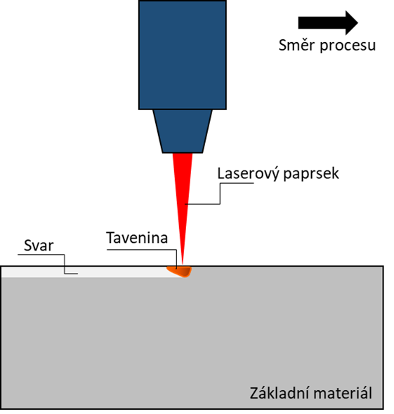
Laser welding focuses optical energy onto a joint, where the workpiece absorbs part of that energy and converts it into heat. The material melts in conduction mode or forms a vapor cavity in keyhole mode; the moving molten pool then solidifies behind the beam to create the weld.
Absorbed laser energy creates a localized molten pool; the unabsorbed portion may be reflected, transmitted or lost to the surroundings.
Power density, travel speed, spot size and material response determine whether the weld stays shallow or develops deep penetration.
Clean surfaces, control fit-up, select parameters, shield the pool, monitor the process and inspect the finished joint.
A visually attractive bead is not proof of penetration, internal soundness, strength or repeatability.
The direct answer
How does laser welding work?
A laser source generates a beam that is delivered through fiber or optics and focused onto the joint. Once the workpiece absorbs enough energy, a molten pool forms. At higher power density, evaporation and recoil pressure open a narrow vapor cavity—the keyhole—which lets energy couple deeper into the material. As the beam advances, liquid metal flows around the interaction zone and solidifies into a seam.
The practical meaning
Laser power alone does not define the weld. The result comes from the complete energy distribution: power or pulse energy, focused spot, beam profile, travel speed, focal position, wobble pattern, material absorptance, joint fit-up, filler delivery and shielding. Change one variable and penetration, bead width, cooling rate or defect risk may change with it.
Laser welding is often called a low-heat-input process, but that phrase needs context. The beam delivers very high power density to a small region and can move quickly, so the total energy introduced per unit length may be lower than in a slower process. The weld and heat-affected zone can therefore be narrow. That does not mean the fusion zone is cool, nor does it guarantee low distortion on every component.
The process can join steels, stainless steels, aluminum alloys, nickel alloys, titanium, copper alloys and selected dissimilar combinations. Each material has its own optical, thermal, metallurgical and surface-condition challenges. Reflectivity changes as the surface heats; alloying elements can vaporize; fast solidification can create hard phases or cracking; and contamination can turn into porosity.
Technical basis: TWI’s laser welding overview, EWI’s mode comparison, and NIST research on dynamic absorption and keyholes.
Working principle
The weld begins with energy coupling—not simply “high power”
When the focused beam reaches the workpiece, part of the light is absorbed and part is reflected. Absorptance depends on wavelength, surface condition, temperature, angle and the evolving melt geometry. The absorbed energy raises the local temperature through melting and, when sufficiently intense, evaporation.
In a stable keyhole, repeated reflections inside the cavity can increase energy coupling. The same cavity can become a defect source if it fluctuates or collapses and traps vapor as the pool freezes. NIST therefore describes keyholes as beneficial for absorption and penetration but potentially harmful when they trap pores.
The source, fiber, collimator and focusing optics determine beam quality, focal diameter and usable working distance.
Surface chemistry, roughness, temperature and wavelength determine how much incident energy enters the workpiece.
Conduction, convection, surface tension, recoil pressure and gravity shape the molten pool.
Travel speed, heat extraction and alloy chemistry control cooling rate, microstructure, residual stress and possible cracking.

Interactive process map
Six physical stages of a laser weld
Select a stage to see what is happening, what controls it and what evidence should be checked. These stages overlap in real time as the beam travels.
Place the energy where the joint needs it
The optics focus the beam at or near the joint. Focus position, working distance, head angle, seam tracking and fit-up determine whether the intended spot actually lands on both members.
Two operating regimes
Conduction welding vs keyhole welding
The modes are not separate machine types. They are outcomes of laser–material interaction. Increasing power density or reducing travel speed may move a process from surface melting toward vapor-cavity formation, but the transition depends on the material and beam.
Wide, shallow fusion
The surface melts without sustaining a deep vapor cavity. Heat travels into the material mainly by conduction and melt-pool convection.
- Useful for thin sections, edge sealing and appearance-sensitive seams.
- Usually lower depth-to-width ratio.
- Excess energy can still cause overheating, oxidation or distortion.

Deep, narrow penetration
Evaporation creates recoil pressure that depresses the melt surface into a vapor cavity. Multiple reflections can deliver energy deeper into the joint.
- Useful when penetration and high travel speed are priorities.
- Higher depth-to-width ratio than conduction welding.
- Keyhole instability can produce porosity, spatter or humping.
| Decision factor | Conduction mode | Keyhole mode | What must be verified |
|---|---|---|---|
| Penetration profile | Typically wider and shallower | Typically narrow and deep | Cross-section at the minimum, nominal and maximum parameter set |
| Dominant mechanism | Surface absorption followed by heat conduction and convection | Vapor cavity, internal reflections, recoil pressure and strong melt flow | Stable regime throughout starts, stops, corners and gaps |
| Appearance | Often smoother when correctly controlled | Can be narrow and clean but is more sensitive to keyhole instability | Bead profile, undercut, oxidation and spatter |
| Main defect concern | Lack of fusion, excessive width or overheating | Porosity, collapse, spatter, humping or incomplete penetration | Internal inspection and destructive validation where required |
Mode descriptions follow EWI, TWI, and the open review of keyhole welding physics and modelling.
Planning aid
Which process direction deserves the first trial?
This selector is a conservative starting point, not a welding procedure specification. Final settings require representative samples, cross-sections and application-specific acceptance criteria.
Compare controlled conduction and shallow keyhole trials
A moderate section with balanced geometry does not justify choosing a mode from thickness alone. Establish the transition region, then compare penetration, bead profile and defect response.
- Hold joint preparation and focal position constant.
- Run a structured power–speed matrix.
- Cross-section representative welds before selecting the window.
System components
What equipment turns a laser source into a repeatable weld?
A stable weld depends on the complete delivery and control chain. Source power cannot compensate for contaminated optics, incorrect focus, poor seam tracking, unstable wire feed or inadequate shielding.
Basic process
Eight steps from part preparation to weld release
A robust process begins before the laser turns on and ends only after the acceptance evidence is reviewed.
Define the requirement
Record material grade and condition, thickness, joint type, penetration target, appearance limits, strength or leak requirement, production rate and inspection standard.
Prepare the surfaces
Remove oil, moisture, paint, oxides and debris from the fusion zone. Cleaning must match the alloy; aggressive abrasion can embed contamination or change fit-up.
Build the joint and fixture
Control edge condition, gap, mismatch and clamping. Provide access for the beam, shielding gas, wire and any backside protection or heat sink.
Verify optics and focus
Inspect the protective lens, confirm focus and standoff, check beam centering and verify the programmed or manual path reaches both joint members.
Set the process window
Establish power, speed, focus, spot or wobble, wire feed and gas using a controlled test matrix. Include starts, stops, corners and realistic production tolerances.
Execute and monitor
Maintain travel, angle, standoff and filler position. Watch for plume, spatter, unstable sound, excessive glow, interrupted wire, contamination or seam-tracking error.
Inspect the joint
Use visual and dimensional inspection plus cross-section, leak test, tensile, bend, radiography, CT or another method appropriate to the acceptance risk.
Lock and control the recipe
Document the qualified range, consumables, optics condition, fixture, cleaning method and inspection plan. Track drift rather than treating the first good bead as permanent proof.
Parameter interactions
Which laser welding parameters control penetration and quality?
Parameters work as a coupled system. Changing travel speed changes energy per unit length and exposure time; changing focus changes spot area and power density; changing wobble redistributes energy and can improve gap tolerance while reducing peak penetration.
Raises available energy and potential penetration, but excess power can destabilize the keyhole, increase spatter or overheat a thin section.
Controls interaction time and line energy. Too fast may cause incomplete fusion or humping; too slow may widen the pool and raise heat input.
A smaller spot generally increases power density. Focus position changes where peak intensity sits relative to the surface and joint.
Core/ring distribution or scanner motion changes melt-pool width, mixing, gap tolerance and stability.
Gas type, nozzle geometry, direction and flow influence oxidation, plume behavior and bead appearance. More flow is not automatically better.
Wire alloy, diameter, angle, contact point and speed must be synchronized with melt demand. Poor delivery can cause sticking, lack of fusion or excess reinforcement.
A narrow beam has limited bridgeability. Wobble, filler and fixture changes may help, but geometry must remain inside the qualified range.
Oil, oxide, coating and roughness change absorption and can introduce gas or inclusions. Use a defined preparation method.
Part mass, clamps, backing bars and adjacent features alter heat extraction, cooling rate and distortion.
Nominal line-energy calculator
For a continuous-wave process, nominal line energy is laser power divided by travel speed. This is a comparison metric—not a complete predictor of penetration—because absorption and losses change during welding.
Use the nominal value to compare recipes on the same system. The absorbed estimate is illustrative because absorptance is dynamic and may increase sharply when a keyhole forms.
The parameter set and monitoring context are consistent with the open review Review and Analysis of Modern Laser Beam Welding Processes. Dynamic absorptance limitations are discussed by NIST.
Material response
Why does the same laser recipe behave differently on different metals?
Optical absorption is only the first difference. Thermal conductivity, melting range, vapor pressure, oxide chemistry, solidification behavior and phase transformation determine whether a recipe stays stable.
Carbon and alloy steels
Usually couple well once heating begins, but rapid cooling may form hard microstructures. Carbon equivalent, restraint and hydrogen control matter.
Stainless steel
Often produces clean seams, yet shielding and heat control affect oxidation, ferrite balance, sensitization and appearance.
Aluminum
High thermal conductivity, surface oxide, hydrogen-related porosity and hot cracking can narrow the process window. Cleaning and filler selection are important.
Copper and brass
High conductivity and strong room-temperature reflection challenge energy coupling. Brass also introduces zinc-vapor behavior and fume-control requirements.
Titanium
Can weld effectively, but the hot metal is highly sensitive to oxygen, nitrogen and hydrogen. Extended shielding may be required.
Dissimilar metals
Melting-point differences and brittle intermetallic compounds can dominate. Joint design, beam offset, filler or interlayer may be more important than raw power.
Maximum weldable thickness depends on alloy, joint geometry, beam quality, power, mode, speed, focal condition, shielding, filler and the required acceptance level. A demonstration bead on one alloy does not qualify another application.

Quality monitoring
A bright, smooth top bead is only one piece of evidence
Laser welding happens quickly and often produces a narrow seam, so visual inspection alone can miss incomplete penetration, subsurface porosity, internal cracking or lack of fusion. The monitoring plan should match the failure consequence and the acceptance requirement.
Modern systems may observe reflected laser light, thermal or visible emission, plume behavior, camera images, acoustic signals or weld depth. Optical coherence tomography can measure joint position before welding and features of the keyhole or solidified seam during and after welding. These signals become useful only after they are correlated with verified weld quality.
Material identity, surface cleanliness, gap, mismatch, fixture and focus.
Power, speed, tracking, wire, gas, plume, spatter, emission and weld-depth signals.
Appearance, geometry, section, leak, strength, hardness and internal NDT as required.
See the peer-reviewed study of scanning OCT for laser-welding melt-pool and keyhole monitoring.
Troubleshooting
Common laser welding defects and what they indicate
A defect rarely has one universal cause. Diagnose from the joint, cross-section, parameter history and monitoring signals instead of changing power at random.
| Symptom | Possible mechanism | Check first | Validation evidence |
|---|---|---|---|
| Incomplete penetration | Low delivered power density, excessive speed, focus error, beam off joint, large gap or optical contamination | Actual power, lens condition, focus, path, speed and fit-up | Cross-sections through steady state and transitions |
| Porosity | Contamination, hydrogen, coating vapor, unstable or collapsing keyhole, poor gas coverage | Cleaning, alloy/coating, keyhole stability and gas setup | Radiography/CT or sectioning plus process correlation |
| Spatter | Excessive peak power density, unstable keyhole, wire misfeed, surface contamination or plume interaction | Power–speed balance, focus, wire position and cleanliness | High-speed/process signal comparison and bead inspection |
| Undercut or concavity | Excessive speed, melt ejection, poor filler balance, wide wobble or unfavorable pool flow | Speed, wobble, wire rate and torch/head angle | Profile measurement and cross-section |
| Cracking | Alloy solidification range, restraint, filler mismatch, rapid cooling, hard transformation or brittle compounds | Material identity, joint restraint, filler and thermal cycle | Metallography, hardness and mechanical test |
| Oxidation/discoloration | Insufficient or turbulent shielding, long hot zone, contaminated gas line or backside exposure | Gas purity, nozzle position, flow, trailing coverage and backing | Appearance plus corrosion/chemistry requirement where relevant |
| Humping | High-speed melt-pool instability and unfavorable fluid flow | Travel speed, spot/profile, focus and bead geometry | Surface profile and qualified speed window |
High-speed humping mechanisms are discussed in the U.S. Department of Energy overview X-rays Reveal Why High-Speed Welding Goes Wrong.
Safety
Industrial laser welding requires engineered controls
High-power laser welding systems commonly contain a Class 4 source. The hazard is not limited to the bright process emission: direct or reflected laser radiation can be invisible, and the process can also create fumes, hot metal, fire, electrical, compressed-gas and mechanical-motion hazards.
Enclose and interlock
OSHA guidance gives primary consideration to engineering controls and recommends enclosing the beam path and interaction area whenever possible.
Control the area
Define the laser controlled area, restrict access, terminate the beam safely, post warnings and provide activation indicators and emergency stops.
Select wavelength-specific PPE
Eyewear must match the wavelength and required optical density. Ordinary welding shade or generic glasses are not a substitute for a hazard assessment.
Capture process emissions
Use source-capture extraction appropriate to the base metal, coating, filler and production rate. Some fumes require additional controls.
Manage reflections and fire
Remove unintended shiny objects, use suitable screens and beam stops, control combustibles and plan for hot work and spatter.
Train and verify
Use a qualified laser safety program, documented procedures, inspections and competent supervision for operation, maintenance and service.
OSHA states that engineering controls should receive primary consideration and that eye protection is used when accessible emissions cannot otherwise be reduced below applicable exposure limits.
Safety reference: OSHA Guidelines for Laser Safety and Hazard Assessment. Apply current local regulations and a site-specific assessment.
Applications and limits
Where laser welding is most valuable
Laser welding is strongest where concentrated heat, accurate placement, high travel speed, low post-processing and automation create real production value. It is less attractive when gaps are uncontrolled, access is poor, volume is low and the quality requirement does not justify the system.
Battery components, tailored blanks, powertrain parts, sensors and body structures where speed and automation matter.
Small housings, contacts, tabs and hermetic or precision seams with limited heat exposure.
Fine stainless or titanium assemblies requiring controlled geometry, cleanliness and documented validation.
Precision assemblies and thin structures where distortion, repeatability and material integrity are tightly controlled.
Cabinets, kitchenware, doors, tanks and visible seams suited to handheld or automated welding.
Fuel cells, heat exchangers, batteries and busbars requiring conductive, sealed or repeatable joints.
Localized repair and build-up when filler, heat input and finishing are carefully controlled.
Enclosures and components where a continuous narrow seam supports leak-tight performance after validation.
Turn the principle into a process
Validate your material, joint and production target
Send representative material, thickness, joint photos, target penetration, appearance standard, production volume and available power supply. Oceanplayer can use that information to recommend a machine direction and sample-test plan.
Continue the decision
Laser welding tools and next-step guides
Frequently asked questions
Laser welding principle and process FAQ
What is the basic working principle of laser welding?
A focused laser beam delivers energy to the joint. The workpiece absorbs part of the light and converts it into heat, forming a molten pool. In keyhole mode, evaporation creates a narrow vapor cavity that increases penetration. The moving pool solidifies behind the beam and forms the weld seam.
What are the main steps in the laser welding process?
Define the requirement, prepare the surfaces, control joint fit-up and fixturing, verify optics and focus, set a qualified parameter window, execute with shielding and monitoring, inspect the weld, and document the approved recipe and maintenance controls.
What is the difference between conduction and keyhole laser welding?
Conduction welding melts the surface and transfers heat into the material, normally producing a wider, shallower weld. Keyhole welding uses sufficient power density to create a vapor cavity, allowing deeper and narrower penetration. Neither mode is universally better; the required geometry and defect risk determine the choice.
Does higher laser power always create a better weld?
No. Higher power may increase penetration, but if speed, focus, spot size, fit-up and shielding are not balanced it can destabilize the keyhole, increase spatter, cause undercut or overheat the part. Delivered power and the complete process window must be qualified together.
Why is laser welding usually associated with low distortion?
The beam concentrates energy into a small region and often travels quickly, which can reduce total energy per unit length and keep the heat-affected zone narrow. Distortion still depends on part geometry, restraint, thermal mass, weld sequence and recipe.
Is filler wire required for laser welding?
Not always. Autogenous welding can work when fit-up and metallurgy permit. Filler wire may be needed to bridge a controlled gap, change weld chemistry, reduce cracking, replace lost alloying elements or shape the bead. Wire position and speed then become critical process variables.
Which shielding gas is used in laser welding?
Argon, helium, nitrogen or a qualified mixture may be used depending on material, laser type and quality objective. Gas purity, nozzle geometry, direction and flow matter as much as the gas name. Reactive materials or full-penetration joints may also need trailing or backside shielding.
How is laser weld quality checked?
Checks can include visual and dimensional inspection, etched cross-sections, tensile or bend testing, hardness, leak testing, radiography, ultrasonic testing or CT. Inline sensors may monitor joint position, optical emission, reflected light, sound, images or weld depth, but those signals must be correlated with verified quality.
Can laser welding join aluminum and copper?
Yes, but both can be demanding because of thermal conductivity, reflectivity and alloy-specific defect mechanisms. Aluminum also raises oxide, hydrogen porosity and hot-cracking concerns; copper may need optimized wavelength or beam distribution. Representative sample testing is essential.
What safety controls are needed for laser welding?
Use a formal laser hazard assessment. Engineering controls such as an enclosure, interlocks, access control, beam termination, warning systems and source-capture extraction take priority. Wavelength-specific eye protection, protective clothing, hot-work controls and trained supervision are added according to the residual hazard and local rules.
Technical references
Sources used to verify this guide
- TWI: What is Laser Welding and How Does it Work?
- EWI: Conduction Mode vs. Keyhole Mode Laser Welding
- NIST: Measuring Dynamic Light Absorption During Laser Welding
- Laser Welding Process—A Review of Keyhole Welding Modelling
- Review and Analysis of Modern Laser Beam Welding Processes
- In-Process Analysis of Melt Pool Fluctuations with Scanning OCT
- U.S. DOE: X-rays Reveal Why High-Speed Welding Goes Wrong
- OSHA: Guidelines for Laser Safety and Hazard Assessment