

How to Replace a Laser Welding Protective Lens
A laser welding protective lens—also called a protective window or cover glass—is the replaceable optical barrier that shields more expensive focusing and collimating optics from spatter, fumes and dust. Replacing it correctly is a contamination-control task as much as a mechanical task: identify the exact lens and holder, isolate the machine under the approved energy-control procedure, work in a clean area, handle the optic only by its edge, preserve the seal and restore the head exactly as the manufacturer specifies.
Stop and isolate the machine, verify zero hazardous energy, clean the outside of the head, prepare a clean station, remove the drawer without exposing the cavity to dust, replace the correct lens and seal in the documented orientation, reinstall the holder, inspect the assembly, then return the machine to service using the manufacturer's approved checks. Do not improvise a live “low-power alignment” test.
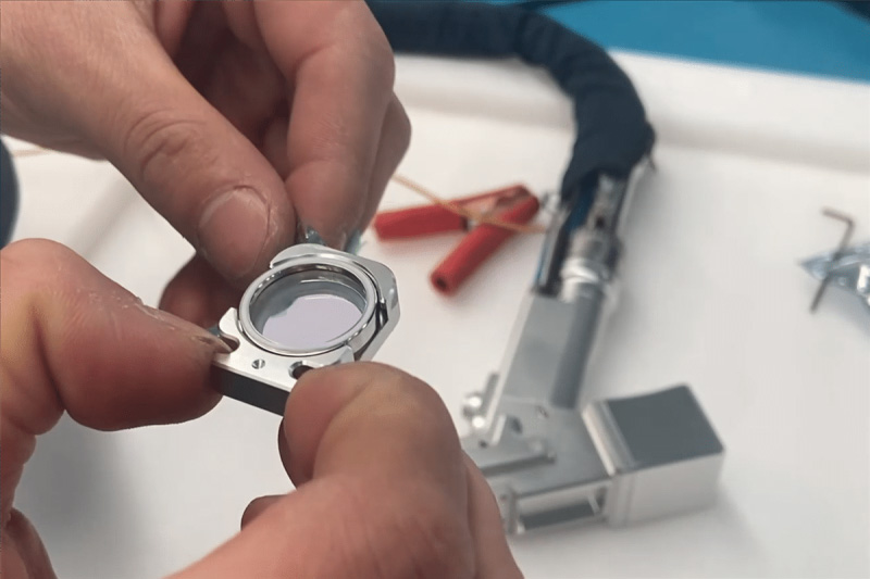 Model-specific procedure required
One dust particle, fingerprint or damaged seal can turn a simple consumable replacement into an expensive head repair.
Image reference: DP Laser protective-lens guide.
Treat the lens change as an optical service task.
The holder may look simple, but compatibility, cleanliness and sealing determine whether the new window protects the internal optics or becomes the next failure point.
“20 mm protective lens” is not enough information to prove optical or mechanical compatibility.
Use the employer's documented procedure and the machine manual; an emergency stop alone is not a service isolation.
Clean the head exterior before opening and prepare covered, lint-free parts on a clean work surface.
Confirm seating, seal, holder engagement and clear aperture before the approved return-to-service check.
Protective window, focusing lens and collimator are not interchangeable.
The protective lens is a sacrificial cover glass positioned near the process end of the welding head. Its job is to intercept spatter, metal vapor, smoke and dust before those contaminants reach the higher-value focusing and collimating optics. Many handheld heads use a drawer-type holder, but dimensions, coating, seal design, orientation, screw arrangement and upper/lower window positions vary.
The focusing and collimating lenses belong to the internal optical train. Replacing those parts can require removal of the head, specialized tools, defined orientation and service calibration. A RayTools BW240 manual, for example, separates cover-glass maintenance from collimation- and focus-lens work and instructs users of other configurations to follow their corresponding installation guide. If contamination has passed the protective window, do not automatically continue deeper into the head.
Routine consumable in many welding heads. Replace when burned, pitted, cracked, permanently hazed or not cleanable under the approved procedure.
Shapes and focuses the beam. Internal service is model-specific; incorrect orientation or contamination can damage the head and change the process.
Condition the diverging fiber output into the optical path. Stop and involve authorized service if these optics are suspected to be contaminated or damaged.
Locate the lens, close the cavity and support gas integrity. A reused, pinched, missing or damaged seal can let contamination reach internal optics.
No lens replacement begins with an energized welding head.
This page is a planning guide, not a substitute for the equipment manual, employer energy-control program or trained service authorization.
Do not open the holder unless the machine is in its approved service-safe state.
Handheld welding systems can present hazardous optical, electrical, thermal, pneumatic, cooling and motion energy. Identify every source that can expose the technician before beginning work.
Stop emission, shut down the system, isolate energy and control the key/plug/lock as required by the manual and workplace procedure.
Do not assume that “off,” standby or emergency stop means zero hazardous energy. Verify the condition by the approved method.
Follow the specified cool-down and pressure-relief sequence. Do not open pressurized or hot assemblies.
Clean gloves protect the optic; they do not replace laser safety controls. Use PPE from the hazard assessment, not generic “laser glasses.”
Some heads and internal optical modules are service-only. Escalate instead of forcing a holder or improvising a disassembly.
Build a clean work zone around the optical cavity.
Most preventable failures begin before the new lens reaches the holder: wrong part, dirty exterior, contaminated gloves, poor air quality or an unprotected open cavity.
Verify parts and documents
Have the welding-head manual open to the correct lens-holder section.
- Exact head model and serial/configuration
- Protective-window part number
- Diameter, thickness and coating
- Seal or O-ring specification
- Documented orientation and fastener method
Prepare approved optical supplies
Use only materials allowed by the lens/head manufacturer.
- Clean nitrile gloves or finger cots
- Cleanroom-grade lint-free wipes or swabs
- Approved lens cleaner or specified anhydrous alcohol
- Rubber bulb blower or specified clean dry air
- Clean covered tray and screw container
Control the environment
Reduce particles before exposing the cavity.
- Clean, dry, well-lit work surface
- No grinding, welding smoke or open windows nearby
- No fan blowing across the open head
- Head exterior cleaned before opening
- Replacement lens package opened only when needed
Eight steps to replace a laser welding protective lens.
The sequence below describes the common logic of a drawer-style protective window. The manufacturer's instructions control every model-specific action.
Confirm the failure and record the condition
Inspect with the machine safe and adequate white light. Photograph burn marks, pitting, haze, cracks and the holder orientation. Record the symptom—power loss, unstable output, temperature alarm or recurring contamination—before disturbing evidence.
Stop immediately for a cracked, burned or visibly deformed window.Shut down, isolate and verify
Apply the approved power-down and hazardous-energy control procedure. Isolate electrical, pneumatic, cooling, motion and other relevant sources. Keep the machine in the verified safe state throughout the replacement.
An emergency stop is not automatically an energy-isolation device.Clean the head exterior and prepare the station
Remove dust and spatter from the outside around the drawer before opening it. Set out the new lens, seal, clean tools and covered tray. Put on fresh lint-free gloves after exterior cleaning.
Do not bring a dirty glove from the gun exterior to the lens edge.Release and withdraw the holder carefully
Support the drawer, loosen only the specified locking screw or cap and withdraw it in the documented direction. Keep it level or vertical as the manual requires. Do not scrape the lens past the head opening.
Never force a stuck drawer; determine why it is binding.Protect the open cavity
Minimize exposure time. Use the manufacturer's approved cavity cover or clean barrier without contacting internal optics. Do not insert paper, adhesive or fibers into the optical path unless the service instructions explicitly specify the method.
The goal is exclusion—not placing a new contaminant near the optics.Disassemble the holder in order
Place it on the clean tray. Remove the cap, retaining ring, sliding ring and seal in the documented sequence. Handle the old lens by its edge. Inspect the holder and seal for particles, nicks, distortion, heat marks and gas-leak paths.
Do not pry a seal with fingernails or a hard tool if the manual prohibits it.Inspect and install the new lens
Inspect both faces under clean light before installation. Remove permitted loose dust with the approved blower. Hold only the edge. Install the lens, seal and retaining parts in the specified orientation; some windows are direction-neutral, while other assemblies are not.
Never infer orientation from another welding-head model.Reinsert, secure and restore service
Confirm the lens is flat, the seal is seated and the clear aperture is free of residue. Reinsert the holder fully and tighten the locking feature to the documented condition. Remove tools and barriers, close guards, then follow the approved restoration and functional-check procedure.
Do not fire an open or unqualified optical path to “see if it aligns.”The holder stack must match your exact welding head.
An exploded illustration helps identify the drawer, retaining parts, window and seal. It cannot confirm the correct sequence for a different head.

Image reference: DP Laser protective-lens guide.
Make the decision from the lens condition.
Inspection frequency and replacement timing are condition-based unless the equipment manual defines a stricter interval.
| Observed condition | Planning action | Reason and boundary |
|---|---|---|
| Loose dust only | Clean if the manual permits | Use an approved blower or cleaning method in a clean area. Reinspect both faces before installation. |
| Light film or removable fingerprint | Clean once using the approved optical method | Use fresh lint-free material and specified cleaner. Do not scrub back and forth or reuse a contaminated wipe. |
| Burn mark, pit or coating damage | Replace | Absorbing defects can heat rapidly in the beam. Cleaning cannot restore a burned coating or pitted surface. |
| Crack, chip or edge damage | Replace and inspect the holder | Mechanical integrity and sealing may be compromised. Determine whether stress, impact or overheating caused the damage. |
| Permanent haze after approved cleaning | Replace | Haze can indicate coating damage, fine spatter or chemical attack that changes transmission and absorption. |
| New lens becomes dirty immediately | Stop and diagnose | Check gas quality/flow, nozzle, seal, holder seating, head orientation, extraction, spatter path and upstream contamination. |
| Internal optics look contaminated | Stop and escalate to authorized service | Do not keep replacing the cover glass while focusing or collimating optics continue to absorb energy. |
| Uncertain lens specification | Do not install | Confirm part number, dimensions, coating/wavelength, power rating, holder and seal with the manufacturer or supplier. |
A clear-looking window can still be wrong for the head. Visual inspection does not prove optical coating, wavelength compatibility or damage threshold.
Repeated failure is usually a system symptom.
Do not turn frequent protective-window replacement into normal maintenance without finding the contamination or thermal source.
Contaminated or unstable gas flow
Moisture, oil, particles, inadequate flow, blocked passages or incorrect timing can let spatter and fume reach the window. Verify the machine's specified gas quality, plumbing and timing.
Damaged, dirty or incorrect nozzle
Nozzle geometry and condition influence gas delivery and spatter shielding. Inspect alignment, aperture, threads and consumable compatibility.
Excessive spatter toward the head
Gun angle, stand-off, joint fit, wire position, surface contamination and parameter selection can direct molten material or vapor toward the protective window.
Back-reflection and unstable coupling
Aluminum, copper and other reflective work can increase optical risk and process instability. Follow the equipment's permitted materials and operating instructions.
Damaged seal or incomplete holder engagement
A twisted seal, dirty groove, loose cap or partially inserted drawer can admit contamination even when the new window is clean.
Heat or contamination already inside the head
Abnormal focus, power loss, alarms or recurring heat after a correct window change may indicate internal optical damage requiring service.
Incorrect coating, thickness or material
A lens that fits physically may still have the wrong optical properties or mechanical support. Use the documented part, not a visual substitute.
Dust and smoke entering during service
Grinding dust, welding fume, fans and careless handling can contaminate a new lens before the head is even reassembled.
Close the optical boundary before restoring energy.
The final inspection is part of the replacement—not an optional cleanup step.
Correct part confirmed
Head model, part number, diameter, thickness, coating and seal match the documented configuration.
Both lens faces inspected
No fiber, dust, fingerprint, scratch, chip, coating mark or cleaner residue under clean white light.
Seal and retaining parts seated
No twist, pinch, missing ring or foreign matter; the lens sits flat without forced pressure.
Holder fully engaged
Drawer/cap returns in the correct direction and the locking feature is secured as specified.
Cavity closed and tools removed
No temporary cover, wipe, packaging, loose screw or tool remains near the head or work area.
Gas, nozzle and extraction reviewed
Correct consumables are fitted and the cause of the old contamination has been considered.
Guards and safety controls restored
Reinstall all covers, interlocks and barriers before removing energy-control devices under the approved procedure.
Approved functional check completed
Use the manufacturer's prescribed inspection/test sequence in the controlled laser area. Stop for abnormal sound, temperature, output, alarm or beam behavior.
Do not blame the new lens before checking the whole head.
These symptoms are prompts for controlled diagnosis, not permission to keep welding through an optical problem.
| Symptom after replacement | First checks | When to stop and escalate |
|---|---|---|
| Power still appears low | Lens specification, cleanliness, seating, seal, holder engagement, nozzle, gas and the same validated job settings. | Internal optic contamination, temperature alarm, unexplained focus change or no improvement after correct reassembly. |
| Output is unstable | Gas consistency, nozzle condition, workpiece cleanliness, wire position, joint fit and protective-window movement. | Irregular beam behavior, smoke from the head, repeated alarm or visible internal contamination. |
| New lens heats or marks quickly | Wrong part/coating, residue on either face, seal leak, spatter path, gas quality and upstream heat. | Any crack, burn spot, smoke, rapid temperature rise or repeated damage—stop immediately. |
| Holder will not seat | Orientation, wrong lens thickness, misplaced seal, retaining ring, debris in groove or damaged drawer. | Do not force it. Escalate if parts do not match the diagram or the holder/head is distorted. |
| Gas leak or abnormal flow | Seal position, holder closure, nozzle, fittings and the manual's pressure/flow checks. | Stop before welding if the optical cavity or process shielding cannot be confirmed sealed and functional. |
| Focus or weld width changed | Wrong lens/holder, incomplete seating, nozzle position and work setup. | Possible focusing/collimating optic displacement or damage requires authorized service and calibration. |
Replace on condition—inspect as often as the risk requires.
A universal “replace every week” rule is not defensible. Inspection frequency depends on the manufacturer, power, material, joint, spatter, gas, environment and duty cycle. xTool's MetalFab guidance, for example, calls for daily pre-operation inspection and more frequent checks on reflective materials such as aluminum and copper. Another head may define a different schedule.
A practical maintenance plan starts with the manual's minimum frequency, then tightens the interval using actual lens-condition records. Record lens hours or shifts, material, process, gas, failure location and reason for replacement. If a pattern changes, investigate the process instead of merely increasing spare-lens inventory.
Check the visible window for dust, grease, burn marks, cracks and abnormal temperature/alarm history.
Stop for unexpected power loss, unstable weld, head-temperature warning, discoloration, smoke or rapid contamination.
Inspect nozzle, gas, seal, holder and process conditions before installing another window.
Use records to find material-, shift-, joint- or operator-related failure clusters and improve the preventive plan.
Send the welding-head model—not just a lens diameter.
Oceanplayer can help identify the relevant documentation and replacement route for supported equipment. Include the exact head, current protective-window marking, holder photos and the failure symptom.
Continue with the correct next step.
Laser Welding Guide
Review materials, joints, parameters, shielding and qualification fundamentals.
Open the guide → Machine selectionWelder Power & Thickness Selector
Compare practical power directions from material and thickness inputs.
Choose a starting route → Process planningWelding Heat Input Calculator
Estimate travel-based energy input for planning and procedure comparison.
Calculate heat input → Maintenance supportAfter-Sales Service
Request documentation, parts guidance, training and equipment support.
View support →Laser welding protective lens FAQ
Short answers to the questions technicians and buyers ask most often.
What does the protective lens do in a laser welding machine?
It is a sacrificial optical window that protects the focusing and collimating optics from spatter, smoke, dust and process debris. It must transmit the intended laser wavelength while maintaining the head's mechanical and sealing requirements.
How often should a laser welding protective lens be replaced?
Replace it based on condition and any mandatory interval in the manufacturer manual. Inspect at the documented frequency and more often when spatter, reflective materials, dirty gas or harsh environments increase contamination. Burn marks, pits, cracks, chips or permanent haze require replacement.
Can a dirty protective lens reduce laser welding power?
Yes. Contamination can reduce transmission and absorb energy, causing heating, unstable performance and damage. Power loss can also come from gas, nozzle, settings or internal optics, so diagnose the system if replacement does not restore normal operation.
Can I clean the lens instead of replacing it?
Loose dust or light removable film may be cleaned when the manufacturer permits it, using approved optical supplies. A burned coating, pit, crack, chip or permanent haze cannot be cleaned back to specification and requires replacement.
Can I use any protective lens with the same diameter?
No. Diameter alone does not confirm thickness, coating, wavelength, optical damage threshold, edge quality, holder fit or seal compatibility. Use the exact documented part or a replacement formally approved for the welding-head model.
Which side of the protective lens faces the laser?
Follow the welding-head manual. Some flat protective windows are direction-neutral; other coated windows or assemblies have a specified orientation. Do not infer direction from appearance or another machine.
Can I use ordinary compressed air to blow the lens?
Only if the manufacturer allows the specified air source. Ordinary shop air may contain oil, water and particles. Some manuals call for a rubber blower or clean dry air. Never blow on the lens with your mouth.
Why does my new protective lens burn quickly?
Common causes include contamination during installation, wrong lens/coating, damaged seal, dirty or incorrect nozzle, unstable or contaminated gas, excessive spatter, reflective work, holder mis-seating or damage inside the head. Stop and diagnose rather than repeatedly replacing lenses.
Should I test alignment with a low-power laser after replacement?
Do not improvise a live-beam alignment test. Restore guards and safety controls, then follow the manufacturer's approved return-to-service inspection and functional-check sequence inside the controlled laser area. Escalate if the procedure is unclear.
What if the lens holder does not slide back in?
Do not force it. Recheck orientation, lens thickness, seal seating, retaining-ring position, debris and damage to the holder or head. Forcing the drawer can break the lens, damage the seal or misplace the optical stack.
When should internal optics be serviced?
Stop and involve authorized service when internal contamination is visible or suspected, the focus changes, alarms persist, power remains abnormal after a correct window replacement, or the manual does not authorize user access to the focusing/collimating modules.
What information is needed to order a replacement lens?
Provide the machine and welding-head model, serial/configuration, exact part number, diameter, thickness, coating or wavelength, holder position, seal specification and clear photos of the label and assembly.