


Single vs Double Pendulum Laser Welding
Single pendulum usually describes one-axis beam oscillation; double pendulum usually describes two-axis steering. A line may be enough for a controlled joint. Two axes add options such as circles and ellipses when the joint needs different energy placement. Choose from demonstrated fusion and repeatability, because the extra axis alone does not establish strength or thickness capacity.
Laboratory laser-welding photograph. It illustrates a welding process, not a comparison of pendulum modes.
Photo: Krorc / Wikimedia Commons, CC BY-SA 3.0. Display cropped with a dark overlay.
What changes when a head has two scanning axes?
The main difference is where the focused spot can move relative to the head. In the common galvanometer design, a driven mirror steers the beam along one axis. Two coordinated axes can generate a two-dimensional path. The head or workpiece still provides the overall travel along the seam.
“Pendulum,” “swing” and “wobble” are commercial terms. A manufacturer’s single-versus-dual comparison uses the one-axis/two-axis distinction, but confirm the actual model. “Double” does not by itself specify two lasers, two spots or two filler wires.
The spot moves along one scan axis. The illustrated line is transverse to forward travel.
Both scan axes move together to trace a loop around the programmed center.
Different axis amplitudes make an elongated path; its orientation matters.
A crossing path adds different visits to the center and the outer portions.
| Capability | One-axis head | Two-axis head |
|---|---|---|
| Scan path | A line along the available axis. Its direction relative to the seam depends on installation and orientation. | Two-dimensional paths, subject to the controller. A line mode may also be available. |
| Independent control | Line width, frequency and waveform as supported. | Potential control of both dimensions, phase, orientation and path shape; not every controller exposes each variable. |
| Width and depth | A wide line can still broaden the seam and reduce depth. | A small circle can still be narrow. Axis count alone does not determine width or penetration. |
| Gap and filler capability | Can work with filler wire when the beam, wire and edges are coordinated. | More ways to steer around the wire and edges; still needs enough metal and stable transfer. |
| Purchase justification | A demonstrated line process meets the joint requirements at the required output. | The extra motion solves a measured problem or is needed for the expected part family. |
On small screens, scroll the table sideways to read all columns.
For example, IPG lists line, circle, figure-eight and infinity modes within its wobble-head range. This is evidence of available beam-path options, not a promise that every two-axis head supports the same functions. For the broader process definition, see what wobble laser welding means.
Why matching “width and frequency” is not enough
A saved recipe is only reproducible when the quantities mean the same thing. Record the path at the workpiece, the optics and focus, laser power, forward speed, waveform, shielding and wire setup.
Separate spot diameter from scan width
Spot diameter describes the focused beam at a stated plane and with a stated diameter convention. Scan width describes its movement. A controller’s “2 mm amplitude” might mean a 2 mm peak-to-peak sweep, a 2 mm radius or a full circle diameter. Ask which definition is used and whether the value is calibrated at the working distance.
At unchanged power, spot profile and focus, widening the scan does not automatically lower the instantaneous intensity inside the moving spot. It changes dwell, revisits and energy deposited around the joint. Defocusing the beam to make the spot itself larger is a different change. Research on EN AW 5083 explicitly distinguishes a small oscillating beam from a larger beam at the same power.
Relate a full scan cycle to forward travel
If v is constant forward speed in mm/s and f is complete oscillation cycles per second, the distance advanced per cycle is p = v / f. This pitch helps compare recipes. It is not a pore limit, a penetration model or a complete overlap percentage.
A calculated example: more cycles, unchanged line energy
Assume a constant 1,500 W beam, 20 mm/s travel and a circular spot-center path with 1 mm radius. These are illustrative inputs, not recommended welding settings.
| Quantity | 100 Hz | 200 Hz |
|---|---|---|
| Advance per complete cycle, v / f | 0.20 mm | 0.10 mm |
| Circular speed relative to the head, 2πrf | 628 mm/s | 1,257 mm/s |
| Incident energy per forward seam length, P / v | 75 J/mm | 75 J/mm |
Scroll sideways on mobile.
The second case revisits the seam more often and moves the spot faster around the circle. It does not halve the incident line energy. Actual spot velocity on the part includes forward travel, and absorbed heat also depends on coupling. Neither column predicts the resulting weld.
Keep beam-oscillation frequency separate from laser pulse frequency or power-modulation frequency. Also ask whether the controller counts complete cycles. For pulsed operation, pulse timing relative to the path adds another variable. In IPG’s copper-welding research, excessive circular speed could destabilize the tested process; a higher frequency was not always better.
Which path should you trial for your joint?
Start from the required fused section and the variation in real parts. A useful trial compares how each path meets those requirements, rather than comparing two attractive surface photographs.
A line can be the production solution
For a repeatable seam with controlled gap and location, test whether a transverse line reaches both edges and produces the required root or interface fusion. If it does, extra patterns may add little value.
A line is also a useful development baseline because it limits the number of path-shape variables. Keep its actual width, orientation and waveform in the record. A sinusoidal line slows near its reversal points, so even a simple path does not have uniform dwell everywhere.
Two axes are useful when energy needs a different path
Trial a circle when repeated motion around the pool may help the joint; an ellipse when the desired spread differs along and across the seam; or a crossing path when you need to investigate a different center-to-edge exposure.
Changing the shape also changes the path length, local velocity and revisits. Compare the required fusion and defects at a useful production speed. A figure eight has no universal advantage over a circle.
For dissimilar-metal connections, inspect mixing and the required electrical and mechanical results. For a visible stainless seam, include both finish and fusion. For a sealed part, define the leak-test requirement. The material or industry name alone cannot select a pattern.
How gap size and filler wire change the choice
Beam motion distributes energy; filler wire adds material. Increasing scan width cannot supply missing metal. An open joint may need improved fit-up, filler wire or a different joint design before a different pattern helps.
For a square butt joint, gap area is approximately thickness × gap width before allowing for the final bead shape. Wire delivery must be related to that demand and forward travel. A lap interface is a different geometry: the aim is a suitable fused connection, not filling the whole overlapping space. The weld root-gap guide explains fit-up and support in more detail.
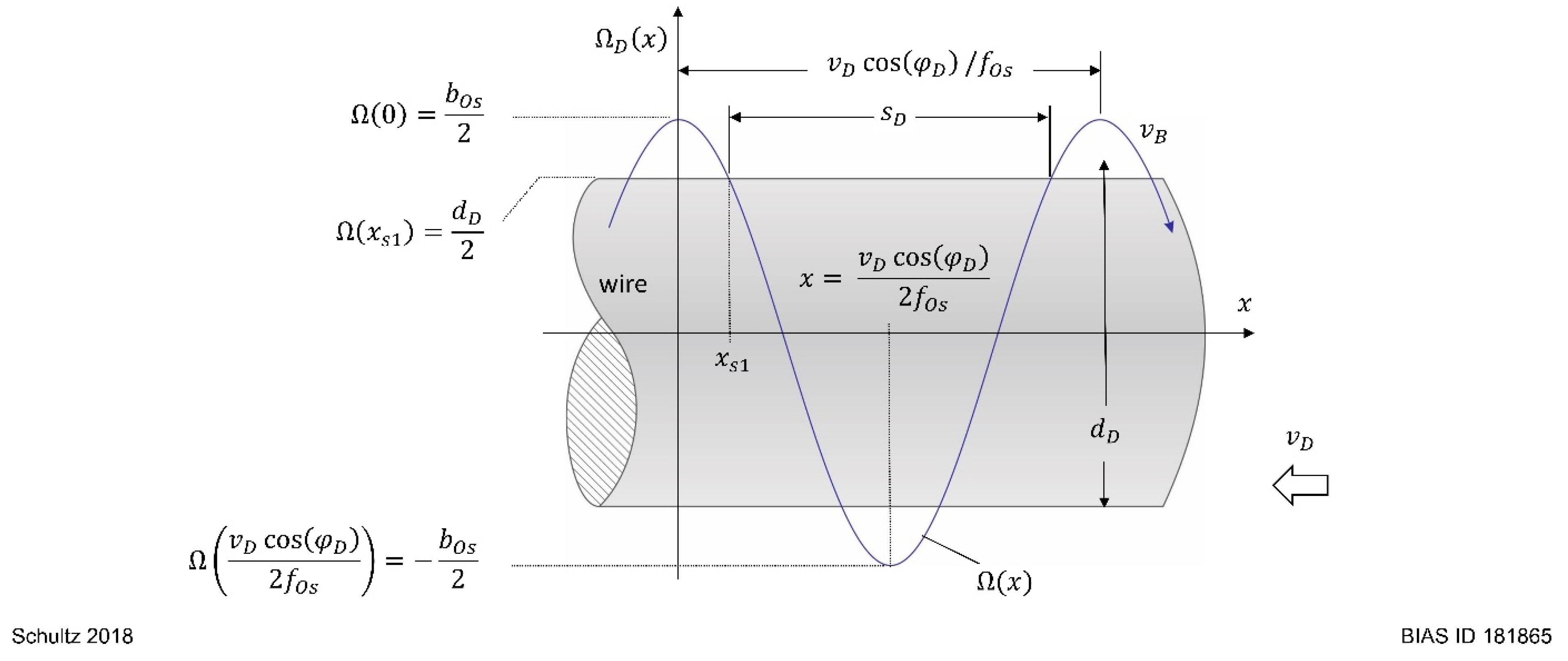
Single-axis welding with wire is a real research configuration
Schultz’s 2019 study used transverse one-dimensional oscillation with 1.5 mm EN AW-6082 sheet and 1.2 mm ML 4043 filler wire. The work linked unstable process transitions to incompletely melted wire segments. It demonstrates why wire–beam coordination matters even with one scanning axis; it does not establish a transferable maximum gap for another machine.
For your trial, record the minimum, nominal and maximum measured gap, wire diameter, feed rate, aim and stability. Judge the fused section and final function. A wider top bead can coexist with underfill or an unfused interface.
When a wider path makes a worse seam
Use the defect’s location and the recorded change to guide the next trial. A symptom can have several causes, so avoid changing power, speed, focus and waveform together without a defined comparison.
| Observed result | What may have changed | Next check |
|---|---|---|
| Wider face, less penetration | Energy deposition has moved away from the required fusion region; focus may also have changed. | Compare sections with the baseline. Verify actual scan width, spot size, focus and delivered power. |
| Periodic or uneven bead | The interaction of travel, scan cycle, waveform or wire feed may be unstable. | Calculate advance per cycle and compare the defect spacing with process records. Inspect wire transfer. |
| One edge wets poorly | Seam offset, torch angle or path orientation may favor the other side. | Check the path center and orientation at the workpiece, then inspect both sides of the section. |
| Pores, spatter or craters persist | The selected path may not stabilize this process; cleanliness, coatings or shielding may also contribute. | Check preparation and gas delivery, then compare candidate paths with suitable internal examination. |
| Underfill or root sagging | Gap volume, wire supply, pool support and heat input may be out of balance. | Measure the gap profile and wire delivery; do not assume greater scan width will restore missing section. |
Scroll sideways on mobile. These are investigation routes, not automatic parameter corrections.
How to compare two heads fairly
Separate a path comparison from a complete-system comparison. Changing the head may also change optics, focused spot, controller behavior and delivered power. An identical display setting does not isolate the effect of the second axis.


- Define the result. Specify material and condition, thickness stack, joint geometry, required fusion, permissible imperfections and the relevant strength, leak or electrical test.
- Establish a reproducible baseline. Identify the head, optics, source, software version and actual spot. Record power, travel, focus, waveform, width definition, frequency, gas and wire setup.
- Test the intended difference. Compare patterns on the same joint and inspection basis. If comparing whole systems, report their configurations and optimize each under the same production constraints.
- Include production variation. Test relevant gap and position limits, starts, stops and corners. For handheld work, include realistic operator variation rather than one unusually favorable pass.
- Release a documented process window. Select the condition that repeatedly meets the requirements. Record allowed ranges, inspection frequency, change controls and actions for abnormal results.
Use sections and the required non-destructive or performance tests to answer specific questions. The laser welding seam-quality guide explains what each type of evidence can establish.
Keep procedure documentation separate from qualification
A welding procedure specification (WPS) describes the process. ISO 15609-4:2009 addresses its content for laser beam welding. ISO 15614-11:2025 addresses procedure qualification testing for electron and laser beam welding. A vendor preset alone is neither a complete WPS nor a qualification record. Use the editions, corrections and acceptance rules required for the actual work.
What should the supplier document?
Ask for a specification and a sample report that identify the complete configuration. The following details make the quotation useful to the team that will run the process.
- Beam steering: active axes, available welding paths, orientation controls and whether a two-axis head can run the required line mode.
- Usable limits together: permitted width and frequency for the selected waveform and optics. Separate maximum values do not prove they are available simultaneously.
- Optical compatibility: wavelength, approved source and fiber connection, power rating, focus range, cooling and guidance for reflective materials.
- Production integration: wire delivery, robot or motion interfaces, seam tracking if needed, recipe storage and alarm handling.
- Service and acceptance: consumables, inspection instructions, scanner calibration, spare-part lead times and a trial report linked to your material and joint.
Can I upgrade a single-axis welder by replacing only the head?
Only if the system manufacturer approves the combination. The optical interface, power handling, cooling, controller, scanner drivers, wiring, interlocks and wire/nozzle arrangement must be compatible. Obtain the required integration and verification steps for the exact replacement; a matching connector is not sufficient evidence.
Will a two-axis head cost more to maintain?
Compare the actual head designs and service schedules. Axis count alone does not determine protective-window consumption, calibration work, repair cost or downtime. Request an itemized service and spare-parts quotation under the expected duty cycle instead of using a universal cost percentage.
To discuss a laser-welding application with Oceanplayer Laser, send the joint drawing, material, measured fit-up range and acceptance requirements. Include the proposed head or current recipe so the evaluation can address the difference that matters to your production.
- Grade, coating and thickness stack
- Joint drawing and measured gap range
- Required fused section and test criteria
- Current settings and failed samples, if available
- Cycle target and production variation