oceanplayer

Oceanplayer Industrial Laser Equipment | Cleaning, Welding, Marking, Automation Sample Testing | Free Engineering Tools | Global Shipping
Main Systems
Best Seller Oceanplayer 500W pulsed laser cleaning machine
Featured Model
500W Pulsed Laser Cleaner

Higher pulse cleaning speed with controlled surface impact.

500W PulsedFine ControlBest Seller
Engineering Tools
Applications
Industries
Company
Resources
Laser Welding QualityInspection & Qualification GuideUpdated July 2026
From appearance to defensible evidence

How to Judge Laser Welding Seam Quality

A smooth top bead is useful evidence—but it cannot prove penetration, internal soundness, hardness, strength, fatigue life or leak performance. This guide shows how to build a layered inspection plan around the drawing, service risk and a qualified welding procedure.

Industrial laser welding process on thick metal plate
The seam is the result of an entire controlled system.Material, fit-up, beam delivery, travel, shielding, metallurgy, monitoring and acceptance evidence must agree.Photo: TRUMPF GmbH + Co. KG, via Wikimedia Commons, CC BY-SA 3.0 DE; display cropped.
First question

What must this joint do?

Cosmetic, structural, electrical, sealed, fatigue-loaded and safety-critical joints need different evidence.

Visual limit

Surface quality is not internal quality.

An even bead cannot reveal every pore, fusion boundary, root condition or metallurgical change.

Method rule

Match the test to the expected flaw.

VT, PT, MT, RT, UT and macrosectioning each answer different questions and have scope limits.

Release rule

Judge against defined criteria.

The drawing, contract, applicable standard, qualified WPS and service validation determine acceptance.

Direct Answer

How do you judge a laser weld seam?

Judge laser welding seam quality with a layered evidence plan: confirm the requirement and welding procedure; inspect joint preparation and process records; perform visual and dimensional examination; verify penetration and fusion on representative cross-sections; select surface or volumetric NDT for the expected flaw, material and geometry; perform mechanical or functional tests that represent service; then correlate production monitoring signals with those physical results.

A seam is not “good” merely because it is smooth. It is acceptable only when the evidence required by the drawing, applicable code or product specification shows that the joint meets its defined quality level and service requirements.

Define “Good” First

Quality is a requirement—not a photograph.

The same visible seam may be acceptable on a cosmetic cover and unacceptable in a pressure boundary, battery connection or fatigue-loaded structure.

Start with the function and failure consequence

Before setting a laser parameter or choosing an inspection tool, define what failure means. A cosmetic joint may prioritize width consistency, distortion and color. A structural joint may prioritize effective fused area, load path, fatigue life and fracture behavior. An electrical joint adds contact resistance and heat rise. A sealed joint adds leak rate and start/stop continuity. A safety-critical joint requires a documented acceptance plan and appropriate engineering authority.

Quality level is not automatically fitness for purpose

ISO 13919-1 and ISO 13919-2 provide imperfection quality levels for laser- and electron-beam welded joints within their material scopes. They describe production quality, not automatic fitness for the product’s service. A designer may need tighter or additional requirements for fatigue, corrosion, pressure, electrical or hermetic performance. Conversely, rejecting a seam against an unrelated generic visual preference can add cost without improving product performance.

Put acceptance criteria on paper

  • Material grade, condition, coating and thickness for every member.
  • Joint type, accessible surfaces, nominal fusion geometry and dimensional tolerances.
  • Applicable quality level, inspection method, sampling plan and acceptance level.
  • Required tensile, bend, fatigue, leak, electrical, corrosion or impact performance.
  • Who can release a part, manage a deviation and approve a process change.
Never invent a universal gap, bead-width or penetration limit.

A value that works for one alloy, joint, optic, wobble pattern and acceptance plan may fail on another. Use drawing requirements, procedure-qualification data and capability studies for the actual production stack.

The Inspection Ladder

Seven gates from weld plan to production release.

No single photograph, sensor trace or coupon proves everything. Use each gate to answer a defined question, and stop escalation only when the required evidence is complete.

01 / Define

Acceptance criteria

Translate service, drawing, code and contract requirements into measurable limits and a sampling plan.

Output: inspection plan
02 / Verify

Inputs and fit-up

Confirm alloy, thickness, coating, cleanliness, joint gap, mismatch, clamping and traceability.

Output: controlled joint
03 / Observe

Process record

Capture qualified settings, focus, speed, shielding, alarms and relevant monitoring signatures.

Output: process evidence
04 / Examine

Visual and dimensional

Inspect top/root condition, profile, width, alignment, starts/stops, spatter and surface-breaking signs.

Output: surface verdict
05 / Reveal

NDT or cross-section

Select a method for the expected flaw and use destructive sections where fusion geometry must be seen directly.

Output: internal evidence
06 / Prove

Mechanical or functional

Test the joint under relevant load, leak, electrical, fatigue, corrosion or impact conditions.

Output: performance data
07 / Control

Production capability

Define limits, sampling, reaction plans, maintenance and requalification triggers for ongoing manufacture.

Output: release system
The evidence must be connected.

Use destructive and NDT results to validate what process-monitoring signals mean. Use production monitoring to detect drift between scheduled verification tests. One layer supports the next; none should be presented as universal proof.

Visual & Dimensional Examination

What a laser welding seam should look like—and what that can prove.

Visual testing is the fastest production screen. It can document surface geometry and continuity, but it must remain within its evidence boundary.

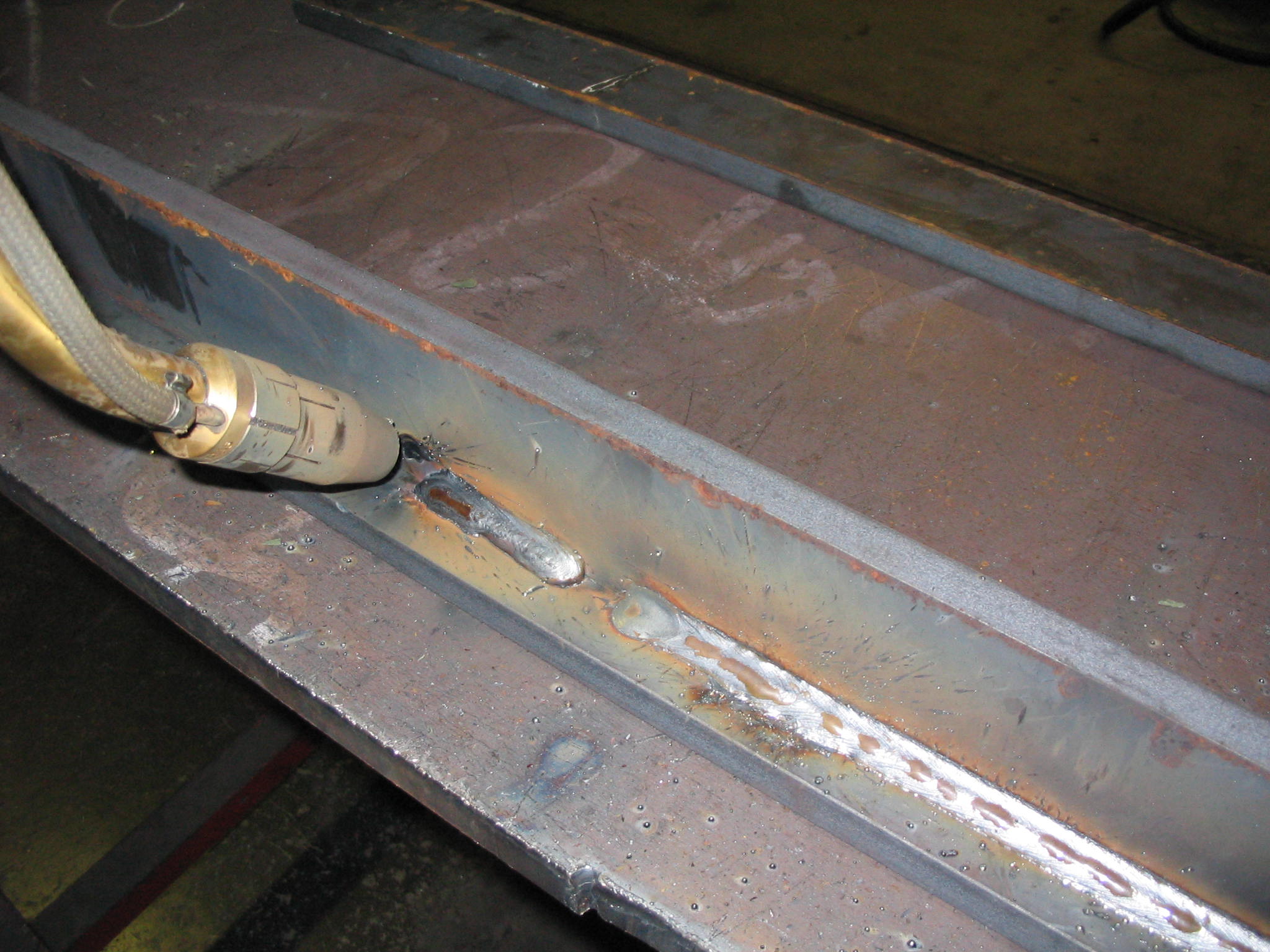
Close view of a welded seam used to illustrate visual surface examination

Read the whole seam, not one attractive section

This non-laser weld photograph illustrates the surface features an inspector follows: continuity, profile, width, toe condition, starts, stops and local anomalies. The applicable acceptance criteria still come from the actual laser-weld specification.

Photo: KOMATSU Ltd, via Wikimedia Commons, CC BY-SA 2.1 JP; display cropped.

Build a repeatable visual routine

  • Prepare the surface: remove loose residue only by an approved method that will not smear or hide indications.
  • Control the view: use suitable lighting, viewing angle, magnification and calibrated measurement tools.
  • Inspect both sides: examine the root whenever accessible; the top surface alone cannot confirm root fusion.
  • Measure, do not describe: record width, reinforcement or underfill, mismatch and location against the specified datum.
  • Map the seam: identify starts, stops, corners, overlaps, changes in section and repaired areas.
  • Preserve traceability: link images and measurements to part, material lot, program, operator/cell and time.
A smooth, narrow bead can still hide incomplete fusion or porosity.

Visual acceptance should trigger the next evidence layer required by the control plan—not end the investigation automatically.

01 / Width & path

Consistency with the drawing

Compare actual seam location and width with the qualified nominal window. Abrupt changes can indicate speed, power, focus, gap or tracking variation. Trend variation instead of assuming one generic target.

02 / Profile

Reinforcement, underfill and undercut

Measure surface profile where required. Undercut can reduce effective section and concentrate stress; excessive reinforcement can also create stress concentration or interference.

03 / Continuity

Starts, stops and overlaps

Look for craters, pores, missed segments, abrupt termination and unqualified repairs. Sealed products need special attention wherever the path begins, ends or restarts.

04 / Alignment

Mismatch and beam position

Part mismatch can change fused area even when the top line remains straight. Compare joint position, fixture datum and beam-tracking record.

05 / Surface signs

Cracks, pits, holes and spatter

Record all visible indications. A surface pit may be the opening of a deeper pore; a fine line may require PT or MT where suitable to determine whether it is crack-like.

06 / Color & residue

Clues—not standalone verdicts

Oxidation tint, soot and deposited metal can indicate shielding or process changes, but color acceptance depends on material, service and product requirements.

Geometry That Matters

Measure the effective joint—not only the visible cap.

Penetration, fused width, root condition and fusion boundaries often control performance. They generally require a qualified internal-inspection or destructive method.

Penetration must match the joint design

A full-penetration butt seam, a partial-penetration structural seam, an overlap weld and a cosmetic surface weld are not judged with the same geometry. “Deeper is better” is not a universal rule: excessive penetration can cause root sag, burn-through, underfill, spatter or damage to an underlying feature. Insufficient penetration can reduce effective section or leave an unbonded path.

Fusion and penetration are different questions

A section can appear deep but still contain lack of sidewall fusion, an unfavorable root shape or an unbonded interface. For lap joints, record the fusion zone through the interface and the effective width or nugget geometry required by the design. For dissimilar materials, measure dilution and reaction-layer features only with a qualified metallurgy plan.

Width-to-depth ratio is descriptive, not a universal pass/fail ratio

Conduction-mode and keyhole-mode welds have different profiles. Power density, source characteristics, spot size, speed, focus, wobble, joint geometry and material response all change the section. Use the qualified nominal profile and tolerance for the actual process rather than a single internet ratio.

Schematic cross section showing fusion zone and heat affected zone in a butt weld

Separate fusion zone, HAZ and base material

The fusion boundary, heat-affected zone and surrounding parent metal may each need dimensional or metallurgical assessment. A top-view photograph cannot separate them.

Diagram: Spangineer; vector derivative by Malyszkz, via Wikimedia Commons, CC BY-SA 3.0.
Defect Map

Common laser-weld imperfections and the evidence they require.

Do not diagnose from appearance alone. The same visible symptom can have several causes, and different defects can create similar process-monitoring signals.

Crack-like

Solidification or centerline cracking

May result from alloy solidification behavior, restraint, unfavorable weld shape, contamination or an unsuitable filler/process window. Some cracks reach the surface; others require sectioning or appropriate NDT.

Useful evidence
VT, PT/MT where applicable, macro/micro examination and fracture/mechanical testing.
Release impact
Evaluate to the applicable acceptance criteria; crack-like indications normally demand immediate engineering review.
Volumetric

Porosity and blowholes

Sources include surface contamination, shielding problems, dissolved gas, unstable keyhole collapse and trapped zinc vapor in coated lap joints. A clean cap can sit above internal pores.

Useful evidence
RT for suitable geometry, macrosections, fracture testing and validated process signatures.
Release impact
Size, distribution, location, joint section and service loading determine significance.
Planar / Fusion

Incomplete penetration or lack of fusion

Power density, speed, focus, beam position, gap, contamination, joint geometry or transient starts/stops can leave unbonded material. Planar flaws may be difficult for an NDT method if orientation is unfavorable.

Useful evidence
Macrosections, qualified UT/RT where geometry permits, fracture and mechanical tests.
Release impact
Compare effective fused section with the design—not nominal laser power.
Surface geometry

Undercut, underfill or excessive reinforcement

Energy balance, travel speed, filler delivery, beam oscillation, joint mismatch or melt ejection can change profile. These features may reduce section, concentrate stress or interfere with assembly.

Useful evidence
VT, profilometry or calibrated dimensional measurement; correlate with section and load tests.
Release impact
Apply the specified imperfection limit and fatigue/service requirements.
Transient

Spatter, humping and surface pits

Unstable keyhole behavior, excessive energy density, poor shielding, joint gap, contamination or an unsuitable speed/wobble combination can eject metal or create periodic profile changes.

Useful evidence
VT/vision, high-speed or optical process data, cross-sections at representative anomalies.
Release impact
Inspect for lost section, embedded contamination, exposed pores and downstream interference.
Metallurgical

Hard or brittle HAZ and unfavorable microstructure

Rapid cooling, hardenable composition, dilution, heat input and joint restraint can create properties that are invisible at the surface. Grain size and hardness are outside the geometric imperfection scope of ISO 13919.

Useful evidence
Metallography, microhardness, tensile/bend/impact/fatigue tests as required.
Release impact
Judge against material, procedure and service requirements—not visual quality level alone.
Choose the Right Inspection Method

Every method has a detection boundary.

ISO 17635:2025 directs method selection by quality requirement, material, thickness, process and extent of testing. Acceptance levels do not map automatically one-for-one to weld quality levels.

Surface / Direct

Visual testing (VT)

Fast, inexpensive and suitable for 100% screening where required. Examines accessible surface geometry, continuity, mismatch and visible imperfections.

Best for
Profile, path, starts/stops, surface openings and dimensional trend.
Cannot prove
Internal fusion, hidden pores, hardness, strength or fatigue life.
Surface / Capillary

Penetrant testing (PT)

Finds discontinuities open to a clean, nonporous surface. Useful on many nonferromagnetic or ferromagnetic materials when the procedure is suitable.

Best for
Fine surface-breaking cracks, laps, pores and open lack-of-fusion indications.
Cannot prove
Closed subsurface defects; ISO 3452-1 does not itself provide weld acceptance criteria.
Surface / Magnetic

Magnetic particle testing (MT)

Detects surface and near-surface imperfections in ferromagnetic materials and the HAZ. It is not suitable for austenitic stainless steels or nonferromagnetic aluminum/copper.

Best for
Crack-like indications in suitable steel components.
Scope check
Use a qualified technique and the applicable acceptance standard.
Volumetric / Radiation

Radiographic testing (RT)

Can image internal volumetric conditions in appropriate joint geometry. Digital and film techniques are covered separately; the technique standard does not itself set acceptance.

Best for
Porosity, cavities and suitable internal geometry.
Limit
Planar flaws may be difficult when their orientation produces little thickness change in the beam direction.
Volumetric / Sound

Ultrasonic testing (UT)

Powerful for qualified applications, but conventional manual ISO 17640 scope is primarily full-penetration ferritic welds, low-attenuation material and thickness of at least 8 mm.

Best for
Appropriate section thickness, geometry and material with a qualified setup.
Limit
Thin, narrow, partial-penetration or nonferrous laser seams may need specialized methods or a different evidence route.
Destructive / Direct

Macro- and micro-examination

Exposes penetration, fusion boundaries, pores, cracks, HAZ and geometric relationships directly at the sampled plane.

Best for
Procedure development, qualification and periodic production verification.
Limit
A section proves only the sampled location; sampling must target transients and representative production.
QuestionLikely first methodOften needs support fromCritical limitation
Is the path and surface profile acceptable?VT plus calibrated dimensional measurementVision/profile data and cross-sectionsSurface evidence only
Is a fine line a surface-breaking crack?PT, or MT on suitable ferromagnetic materialMacro/micro examination and engineering dispositionMaterial and surface condition control method choice
Are internal pores present?RT where geometry and sensitivity are suitableMacrosections, fracture tests, process correlationDetection and acceptance depend on size, distribution and geometry
Did the weld fuse through the designed interface?Macrosection during qualification and verificationQualified UT/RT or functional testing where appropriateA section samples one plane
Is the joint strong enough?Application-relevant mechanical testCross-section, NDT and fracture-location analysisStrength cannot be inferred from bead appearance
Is every production weld stable?Validated in-process monitoring plus VTScheduled destructive/NDT correlationA sensor signal is indirect evidence
Cross-Section Evidence

A macrosection often gives the fastest honest answer.

During development and qualification, a prepared section can reveal the relationship between the visible bead, fused area, root, interface, pores and heat-affected zone.

Technical diagram illustrating an internal welding void and its response to different nondestructive testing directions

Defect orientation changes detectability

A void or planar discontinuity interacts differently with radiation, sound and the prepared section. Method selection must consider likely size, shape, orientation and location.

Diagram: Shigeru23, via Wikimedia Commons, CC BY-SA 4.0.

What to record on a laser-weld cross-section

  • Fusion depth and effective fused width: use the joint-specific drawing definitions, not only total melted depth.
  • Root condition: full, partial or excessive penetration; root underfill, sag or an unfused ligament.
  • Interface behavior: fusion across lap, butt or dissimilar-material boundaries and any trapped coating or void.
  • Imperfections: pores, cracks, lack of fusion, inclusions and their location relative to the effective section.
  • HAZ and fusion boundary: geometry plus any microstructural or hardness examination required by the procedure.
  • Section location: steady-state seam, start, stop, corner, overlap, thickness transition and any monitoring anomaly.
Sampling strategy determines what the section can tell you.

One center-of-seam coupon may miss a start crater, end pore, corner loss of fusion or intermittent tracking error. Place sections from risk locations and statistically representative production.

Prepare It Correctly

Cutting and etching are part of the measurement system.

A damaged section can create false conclusions

Coupon removal, sectioning, mounting, grinding, polishing and etching must preserve the feature under examination. Excessive cutting heat, smeared soft metal, pulled-out particles or deep preparation scratches can resemble defects or hide fine cracks. The preparation method and etchant must suit the alloy and examination objective.

Macro and micro examination answer different questions

Macro examination shows overall penetration, fusion profile, major imperfections and HAZ shape. Micro examination can investigate solidification, phase transformation, grain structure, reaction layers and very small cracks. If hardness or microhardness is specified, use the applicable test method, locations, spacing and load rather than taking informal handheld readings.

Turn sections into a process baseline

Store calibrated section images with dimension annotations, parameter records and the corresponding monitoring trace. A library of acceptable and unacceptable examples is more useful than a generic “good weld” poster because it belongs to the actual material, joint and optics. It also supports future investigations when a signal drifts or a supplier changes a coating.

Strength & Service Performance

A seam passes only the tests that represent its job.

Destructive testing is not a failure of quality control. It is how the team proves what visual, NDT and monitoring evidence mean for the product.

01 / Static load

Tensile or lap-joint testing

Measures load, extension and fracture location for the applicable specimen and joint. A high peak load does not automatically prove fatigue, leak or electrical performance.

Record: failure mode and scatter
02 / Ductility

Bend and fracture testing

Bend tests can expose near-surface imperfections and ductility limitations. Fracture surfaces can reveal porosity, lack of fusion, penetration and inclusions within their standard scope.

Record: indication and location
03 / Metallurgy

Hardness and impact

Use when alloy, cooling rate, service temperature or code makes HAZ/fusion-zone properties important. The correct method, specimen orientation and test temperature matter.

Record: profile, not one value
04 / Product function

Leak, fatigue and electrical tests

Pressure decay, helium leak, cyclic loading, electrical resistance, thermal rise, corrosion or vibration may be the decisive proof for the finished assembly.

Record: service-relevant limits
Compare the fracture location, not only the maximum number.

Parent-metal failure can be useful evidence in a defined test, but it does not excuse hidden process instability or guarantee another load direction. Track strength distribution, fracture path, section geometry and the manufacturing variables associated with every coupon.

NDT Is Application-Specific

Do not prescribe UT because a defect is “inside.”

The suitability of ultrasonic testing depends on wavelength, probe, calibration, material attenuation, thickness, surface, weld geometry and expected flaw orientation. ISO 17640’s common manual scope is not a generic solution for every thin laser seam.

A specialized high-frequency, immersion, phased-array, laser-ultrasonic, OCT or other method may be developed for a specific product—but it must demonstrate sensitivity and repeatability on representative reference flaws and geometry. When that evidence is unavailable, sections, RT, leak tests or destructive sampling may be more defensible.

“Non-destructive” does not mean “complete.”

Every NDT system has a probability of detection, resolution, dead zone and interpretation boundary. State which imperfections it is intended to find and what happens when the result is uncertain.

Technician using a phased-array ultrasonic scanner to inspect a pipeline weld

Qualified geometry matters

This pipeline inspection illustrates how probes, couplant and a guided scanner are configured for a specific joint. Thin precision laser seams may need a completely different validation route.

Photo: Davidmack, via Wikimedia Commons, public domain; display cropped.
In-Process Monitoring

Monitoring detects change. Inspection establishes meaning.

Photodiodes, cameras, pyrometers, acoustic sensors, OCT and coaxial vision can observe the laser-material interaction or seam geometry. They are powerful production controls only after their signatures are correlated with physical weld evidence.

A green signal is not a metallurgical certificate.

A monitoring model identifies patterns inside its validated process envelope. New alloy lots, coatings, geometry, optics, sensor contamination or unrepresented defect modes can reduce confidence.

Photodiode and optical emission

Observes: changes in reflected light, plasma or thermal emission. Needs: correlation to known-good and known-defect welds for the exact process.

High-speed or coaxial vision

Observes: melt-pool/keyhole behavior, spatter, path position and post-weld surface. Needs: controlled optics, lighting and validated image features.

Optical coherence tomography

Observes: pre-, in- or post-weld topography depending on the system, including selected seam/keyhole features. Needs: application-specific access, resolution and interpretation.

Machine and cell data

Observes: commanded/actual power, speed, focus axes, wire feed, gas, alarms and fixture states. Needs: synchronized timestamps and a reaction plan.

Root-Cause Framework

Trace the defect back through five interacting systems.

Changing laser power alone can mask the real cause. Use a structured investigation that preserves the relationship between material, joint, energy delivery, protection and motion.

01 / Material

Alloy and surface

  • Actual grade, temper and chemistry
  • Coating, plating, oxide and oil
  • Thermal conductivity and absorption
  • Crack, porosity or hardening sensitivity
  • Lot-to-lot variation and traceability
02 / Joint

Fit-up and restraint

  • Gap, mismatch and edge condition
  • Lap-interface cleanliness
  • Fixture datum and clamping sequence
  • Heat-sink and backing conditions
  • Starts, stops, corners and transitions
03 / Beam

Energy delivery

  • Power or pulse waveform
  • Spot size, focus and beam quality
  • Travel speed and acceleration
  • Wobble shape, amplitude and frequency
  • Protective-window and nozzle condition
04 / Environment

Shielding and extraction

  • Gas composition, flow and nozzle position
  • Cross-drafts and plume interaction
  • Fume extraction without shielding disruption
  • Backside protection where required
  • Laser-safe enclosure and cleanliness
05 / Filler

Wire and delivery

  • Specified alloy and diameter
  • Feed speed and synchronization
  • Wire angle, position and melt transfer
  • Cleanliness and storage
  • Start/stop and corner behavior
06 / Motion

Path and alignment

  • Calibrated TCP and seam tracking
  • Robot or stage repeatability
  • Part location and thermal movement
  • Head clearance and incidence angle
  • Program version control
07 / Measurement

Inspection capability

  • Calibrated tools and reference standards
  • Inspector or algorithm repeatability
  • Detection sensitivity and blind zones
  • Sampling location and frequency
  • False-call and missed-defect review
08 / Management

Change control

  • Qualified WPS and parameter envelope
  • Authorized repairs and deviations
  • Maintenance and verification schedule
  • Supplier/material change triggers
  • Training and record retention
Production Control Plan

Move from one good coupon to a stable process.

Qualification establishes a defensible process window. Production control confirms that the materials, equipment, joint and evidence remain inside that window.

Control layerTypical production evidenceReaction triggerResponsible question
Incoming materialGrade/heat/lot, temper, thickness, coating and surface conditionUnapproved supplier, coating, chemistry or tolerance changeDoes the qualified WPS cover this actual material?
Joint and fixtureGap, mismatch, location, clamp state and datum checksTrend approaching qualified limit or repeated reworkCan the cell hold the joint before adjusting energy?
Laser systemPower verification, focus/TCP, optics, chiller, nozzle and program versionCalibration drift, alarm, optics contamination or maintenance eventIs delivered energy at the workpiece still verified?
In-process dataPower, motion, shielding, wire feed, sensor signatures and alarmsSignal leaves validated envelope or correlation becomes uncertainWhich physical verification test is required?
Surface inspection100% or sampled VT/vision per control planCrack-like sign, profile trend, missed path or start/stop anomalyStop, segregate and escalate—or continue under defined rules?
Periodic verificationMacrosections, NDT, mechanical/functional coupons and capability trendFailed criterion, abnormal scatter or process/material changeHow much product is potentially affected?
Product validationLeak, fatigue, electrical, corrosion, thermal or dimensional performanceDesign, duty cycle, environment or acceptance requirement changesDoes the joint still meet real service needs?
Define containment before the first nonconformance.

The control plan should state when to stop the cell, identify the last known good part, segregate material, perform confirmatory tests, authorize repair and requalify. Without this reaction plan, fast monitoring only produces fast uncertainty.

Interactive Inspection Planner

What evidence should your seam need next?

Choose the closest case. The result gives an inspection direction, not a pass/fail decision. Final requirements must come from the responsible drawing, code, product standard and qualified procedure.

Screening only

Add internal evidence before release

The default case has a stable-looking surface but no proof of penetration or internal soundness. Use representative sections and the inspection requirements defined for the joint.

  • Confirm the applicable material and quality framework.
  • Section steady-state and transient seam locations.
  • Define visual dimensions and acceptance limits from the qualified procedure.
Priority engineering noteA cosmetic/low-consequence classification still needs defined criteria; appearance is not a substitute for the drawing.
Equipment-Buyer Checklist

Ask for evidence before comparing machines.

A higher laser power does not guarantee a better seam. Compare the complete process capability and validation route for your part.

Send a complete application package

  • Material designation, temper/condition, coating and supplier specification.
  • Thickness of every layer, joint drawing, tolerances and representative real parts.
  • Required fusion or penetration geometry, visible-finish limit and distortion target.
  • Static, fatigue, leak, electrical, corrosion or other functional criteria.
  • Seam length, start/stop restrictions, annual volume and takt-time target.
  • Current defects, inspection method, failed samples and available process data.

Require a sample-test report that connects process and result

A useful report records machine configuration, source, optics, spot/wobble, speed, focus, filler and shielding; identifies the exact coupon/material; shows surface and section results; and recommends a controlled starting window. If the product needs NDT, strength, leak or electrical evidence, agree who supplies it and which acceptance criteria apply before the test.

Evaluate repeatability, not the best photograph

Ask for multiple coupons, starts/stops, corners and tolerance-extreme parts. Compare variation in width, fusion geometry, defects and functional performance. Confirm how the production system detects focus drift, contaminated optics, poor fit-up, wrong program, shielding loss and fixture failure.

The right purchase decision is a qualified process route.

Machine power, cooling and mobility matter, but seam quality is created by the source, head, motion, fixture, shielding, extraction, monitoring, safety system, maintenance plan and inspection capability working together.

Standards Map

Use the current standard inside its stated scope.

This map is a research starting point, not a substitute for the purchased standard, contract hierarchy or a qualified welding/inspection professional.

Imperfection quality

ISO 13919-1:2019

Laser/electron-beam welded joints in steel, nickel, titanium and their alloys, generally from 0.5 mm. Three production-quality levels; not fitness-for-purpose.

Official ISO record →
Imperfection quality

ISO 13919-2:2021

Laser/electron-beam welds in aluminum, magnesium and their alloys plus pure copper, generally from 0.5 mm; similar quality-level limitations.

Official ISO record →
NDT selection

ISO 17635:2025

General rules for selecting NDT by quality requirement, material, thickness, welding process and testing extent; acceptance levels need careful mapping.

Official ISO record →
Visual testing

ISO 17637:2016

Visual testing of fusion-welded joints and, where relevant, examination before welding. It supports surface assessment—not hidden fusion proof.

Official ISO record →
Metallography

ISO 17639:2022

Specimen preparation and procedures for macroscopic and microscopic examination of welds and their parent materials.

Official ISO record →
Procedure qualification

ISO 15614-11:2025

Qualification testing of welding procedures for electron- and laser-beam welding of metallic materials, including new production and repair work.

Official ISO record →
Do not automatically apply ISO 5817 to laser-beam welding.

ISO 5817 excludes beam welding and points users toward the relevant ISO 13919 framework. Product codes and sector requirements may impose additional rules.

Validate Before Equipment Selection

Send the joint, acceptance criteria and real material.

Oceanplayer can review the application information, identify the dominant process risks and recommend a sample-welding route. Final production acceptance remains tied to your applicable specification, qualified procedure and required inspection or product tests.

OP
Oceanplayer Technical TeamIndustrial laser equipment application guidance and sample-test planning
Material grade and coatingThickness and joint drawingActual gap and tolerancesRequired penetration/fusionStrength or leak criteriaPhotos and failed samplesAnnual volume and takt timeCurrent inspection plan
Frequently Asked Questions

Laser-weld seam quality FAQ

Short answers for buyers, operators and quality teams. The applicable drawing and procedure remain the final authority.

What does a good laser welding seam look like?

A visually good seam is continuous, correctly located and within the specified width/profile limits, without unacceptable cracks, pits, undercut, underfill, spatter or start/stop defects. That appearance is only the surface screen; internal fusion, porosity and performance need additional evidence when required.

Can a laser weld look good but still be weak?

Yes. A smooth top bead can conceal incomplete penetration, lack of fusion, internal porosity, unfavorable root shape or metallurgical problems. Cross-sections, appropriate NDT and application-relevant mechanical or functional tests are needed to establish what the appearance means.

How do you check laser weld penetration?

A prepared macrosection is a direct method during procedure development, qualification and periodic verification. Qualified NDT may support production inspection when the material, thickness, geometry and expected flaw are suitable. Define penetration and effective fusion geometry on the drawing or procedure.

Which NDT method is best for laser welds?

There is no universal best method. VT and PT or MT address accessible surface flaws; RT can image suitable volumetric conditions; UT requires suitable material, thickness and geometry; specialized optical methods may serve specific products. Select the method around the expected flaw and prove its sensitivity.

Can ultrasonic testing inspect thin laser welds?

Sometimes with a specially qualified technique, but conventional manual UT is not automatically suitable. ISO 17640’s common scope is primarily full-penetration ferritic welds at least 8 mm thick. Very thin, narrow or complex laser seams may need macrosections, RT, specialized ultrasonics, leak tests or another validated route.

What are the most common laser welding defects?

Common concerns include solidification cracking, porosity, blowholes in coated lap joints, incomplete penetration, lack of fusion, undercut, underfill, spatter, humping and unfavorable HAZ properties. Their frequency and significance depend on material, joint, process and acceptance criteria.

Does ISO 13919 guarantee a weld is fit for service?

No. ISO 13919 quality levels describe production imperfection quality within the stated material and thickness scopes; they are not automatic proof of fitness for purpose. Fatigue, pressure, leak, corrosion, electrical and other service requirements may need additional acceptance criteria and tests.

Can cameras or AI automatically approve every laser weld?

They can provide valuable screening and process control, but only inside a validated application. Algorithms and sensors infer quality from observed features or process signatures. Their results should be correlated with sections, NDT, mechanical or product tests and maintained through change control.

How often should laser welds be destructively tested?

The frequency should come from the applicable code, contract, qualification plan and risk-based production control plan. Consider process capability, part criticality, production volume, material/fixture changes, starts and stops, monitoring confidence and the consequence of an undetected defect.

What information is needed for a laser welding quality review?

Provide exact material and coating, thickness stack, joint drawing and tolerances, required fusion/penetration, service loads, fatigue/leak/electrical criteria, seam path, volume, takt time, existing defects, images and any section/NDT/test data. Real representative parts are preferable to generic scrap.

Technical Sources

Standards and engineering references used.

Always check the current edition, amendments, scope and contract hierarchy before applying a requirement to production.