

6061 Aluminum Thermal Conductivity: T4 vs T6
At about 20°C (68°F), Kaiser lists typical thermal conductivity of 154 W/(m·K) for 6061-T4/T451 and 167 W/(m·K) for 6061-T6/T651. T6 is about 8.4% higher in this dataset. These are useful preliminary design values, not guaranteed minimums or proof that a finished heat sink will run 8.4% cooler.

6061 Aluminum Thermal Conductivity at 20°C
Read the full temper and test temperature before copying a value. The table below uses Kaiser’s typical values at 20°C. Its rod-and-bar sheet groups T4 with T451; its sheet-and-plate document specifically lists T451.
| 6061 condition | Typical k at 20°C | BtuIT/(h·ft·°F) | BtuIT·in/(h·ft²·°F) | How to use it |
|---|---|---|---|---|
| O temper | 180 W/(m·K) | 104 | About 1,250 | Reference for annealed material; not the normal strength choice for a finished structural part. |
| T4 / T451 | 154 W/(m·K) | 89.0 | About 1,070 | Preliminary room-temperature input when naturally aged material and the source conditions match. |
| T6 / T651 | 167 W/(m·K) | 96.5, often rounded to 97 | About 1,160 | Preliminary room-temperature input for artificially aged material under matching conditions. |
Primary values: Kaiser 6061 sheet, coil and plate and Kaiser 6061 rod and bar. Both label the conductivity values as typical.
T6 has 13 W/(m·K) more conductivity in this table: (167 − 154) ÷ 154 × 100 ≈ 8.4%. For an identical simple metal path, that means about 7.8% less bulk thermal resistance, not an 8.4% reduction in the temperature of a complete device.
O temper is annealed and softer. Its higher listed conductivity shows why strength and heat conduction cannot be ranked with one simple rule. Choose the mechanical condition first, then assess the heat path.

What does thermal conductivity actually mean?
Thermal conductivity, written as k or λ, tells you how easily heat moves through the bulk material. A higher value means the same shape can carry more heat for the same temperature difference.
A useful way to picture it: heat passes more easily through a wide, short piece than through a narrow, long one. Conductivity describes the material; the shape determines how much of that advantage the part can use.
Q̇ = kAΔT / LQ̇ is heat flow in W, A is cross-sectional area in m², ΔT is the hot-to-cold temperature difference in K, and L is path length in m.
R = L / (kA)R is thermal resistance in K/W: the temperature difference needed to carry one watt through this path. These formulas assume steady, one-dimensional heat flow and constant k.
Three terms that are often mixed up
- Conductivity k is a material property in W/(m·K).
- Conductance G = kA/L includes the actual geometry and is reported in W/K.
- Thermal diffusivity α = k/(ρcp) describes how quickly a temperature change spreads. Here ρ is density and cp is specific heat capacity. Diffusivity has units of m²/s; it is not the same quantity as conductivity.
Heat-conduction diagram: Chcastan / Wikimedia Commons, public domain.
Why can 6061-T6 conduct heat better than T4?
Heat in aluminum is carried largely by moving electrons. Dissolved alloying atoms can interrupt that movement. Heat treatment changes how magnesium, silicon and other elements are distributed—not the alloy’s name or its purity grade.
Solution treatment and quenching
Solution treatment dissolves more alloying elements into the aluminum. Rapid cooling, called quenching, temporarily traps many of those atoms in place.
T4: natural aging at room temperature
During natural aging, small groups of atoms form at room temperature. This changes strength, but is not the same process as a controlled artificial-aging cycle.
T6: controlled artificial aging
Artificial aging forms fine particles called precipitates. It can reduce the amount of dissolved solute that scatters electrons, while the particles strengthen the alloy. This helps explain the conductivity difference in the cited tables.
Mechanism: Metallurgy of Heat Treatment, hosted by NIST. The relationship depends on the actual aging history; strength alone does not determine k.

This diagram shows the main path to T6. Real soak, quench and aging practice depends on the product and qualified procedure.
Diagram: Bob Clemintime / Wikimedia Commons, CC BY-SA 4.0.

An etched 6061-T6 microstructure shows grain boundaries and secondary phases. It is not a direct heat-flow map or a universal structure for every 6061 product.
Image: Bob Clemintime / Wikimedia Commons, CC BY-SA 4.0.
Why the actual value can vary
Composition within 6061 limits, quench rate, aging history, product form, defects and test temperature can shift the result.
- T6 is not always exactly 167 W/(m·K).
- T4 is not always exactly 154 W/(m·K).
- Electrical conductivity is related to heat conduction, but is not the same measurement.
- Hot service or welding can change the local temper.
Convert W/(m·K) to BTU units correctly
Thermal conductivity contains power, length and temperature-interval units. Multiplying watts by 3.412 alone does not convert the complete quantity.
BtuIT/(h·ft·°F) = W/(m·K) × 0.577789154 becomes 88.98, normally shown as 89.0. 167 becomes 96.49, often rounded to 97.
W/(m·K) = BtuIT/(h·ft·°F) × 1.730735Use this inverse only for the complete foot-based conductivity unit.
BtuIT·in/(h·ft²·°F) = W/(m·K) × 6.93347The inch-based number is 12 times the foot-based number. Write the full unit: Btu·in/(h·ft²·°F) is not Btu/(h·in·°F).
W/(in·K) = W/(m·K) × 0.0254T4 becomes 3.91 W/(in·K), while T6 becomes 4.24 W/(in·K).
| Starting value | BtuIT/(h·ft·°F) | BtuIT·in/(h·ft²·°F) | W/(in·K) | W/(m·°C) |
|---|---|---|---|---|
| 6061-T4/T451: 154 W/(m·K) | 89.0 | About 1,070 | 3.91 | 154 |
| 6061-T6/T651: 167 W/(m·K) | 96.5 | About 1,160 | 4.24 | 167 |
Conversion factors follow the NIST Guide to the SI, Appendix B.9. The table uses the international-table Btu, BtuIT.
W/(m·K) and W/(m·°C) have the same numerical conductivity because kelvin and Celsius intervals are equal in size.
Add 273.15 only when converting an absolute Celsius reading to kelvin. Do not add it to a temperature difference.
The 32-degree offset belongs to absolute temperature readings, not temperature differences used in conduction formulas.
How does T4 vs T6 affect a part’s temperature?
Illustrative calculation—not a product test. Consider a solid path 50 mm long with a 20 mm × 20 mm cross section. Hold the cold end at 20°C and send 10 W through it. In SI units, L = 0.050 m and A = 0.000400 m².
R = L/(kA)This example assumes steady, one-dimensional conduction, constant k, no contact resistance and no internal heat generation.
| Result | T4 at 154 W/(m·K) | T6 at 167 W/(m·K) |
|---|---|---|
| Bulk resistance | 0.812 K/W | 0.749 K/W |
| Temperature difference at 10 W | 8.12 K | 7.49 K |
| Difference | T6 lowers the calculated hot-end temperature by about 0.63°C. | |
Using these constant room-temperature values gives hot ends of about 28.1°C and 27.5°C. The small temperature rise keeps the illustration close to the reference condition; it still does not replace temperature-dependent material data for a critical design.
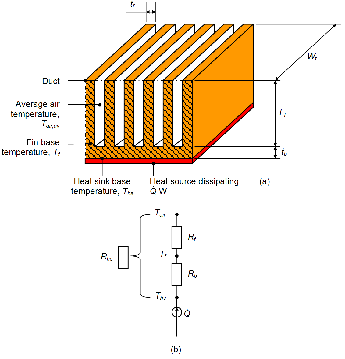
A real heat path contains several resistances, not only the aluminum. Diagram: Dtc5341 / Wikimedia Commons, public domain.
Why do 6061 conductivity values differ between sources?
A different number is not automatically a mistake. Compare the product, temper, temperature and measurement basis before deciding which source fits your part.
k changes with temperature
The Kaiser figures are at 20°C. A room-temperature value should not be carried across cryogenic or high-temperature service without a matching k(T) dataset.
Plate is not automatically extrusion
Hydro lists typical extruded T4/T4511 conductivity of 155 W/(m·K) at 25°C, while Kaiser’s rod/bar value is 154 at 20°C. Both the product basis and temperature differ.
Keep the stress-relief suffix
T451, T651, T4511 and T6511 record different processing routes. Do not shorten the ordered condition because the conductivity table groups some values.
Critical designs need matching specimens
Texture, porosity, coatings, specimen direction and local defects can affect measured or effective conductivity.
Welding and hot exposure matter
A weld, brazing cycle, solution treatment, aging cycle or long hot bake can change the local precipitation state and the final part.
Match the evidence to the design risk
Move from handbook value → supplier-specific value → temperature curve → lot test → assembly validation as the risk and thermal sensitivity increase.


Fin height, spacing, base thickness, source footprint and airflow often control more of the total result than 13 W/(m·K).
Aluminum heat-sink profiles; alloy and temper are not certified by the image. Ulfbastel / Wikimedia Commons, public domain.
Should you choose T4 or T6?
Do not choose the temper from conductivity alone. The manufacturing route and final mechanical requirements normally come first.
Choose T4 or T451 when
- The part needs meaningful forming before its final age.
- The producer or fabricator will artificially age it after forming.
- Lower strength in the supplied state is acceptable.
- Your preliminary model can tolerate the lower typical k.
Choose T6 or T651 when
- The finished part needs the strength associated with the specified artificially aged condition.
- A stress-relieved product such as T651 is specified for machining stability; T6 alone does not mean the same stress-relief treatment.
- The modest conductivity increase helps a bulk conduction path.
- Later welding or heating is included in the material and process plan.
Keep the full suffix
T651 and T6511 are not decorative names. The Aluminum Association notes that temper designations represent different processing parameters and should not be treated as automatic substitutions.
Where does 6061 thermal conductivity matter most?
The same alloy value can be important in one product and almost irrelevant in another. Identify which part of the heat path controls temperature.
Heat spreaders and cold plates
The benefit grows when heat travels a long in-plane distance through the aluminum. Also check channel walls, flow distribution, sealing and the source interface.
Electronics enclosures
Mounting pads, flatness, thermal interface material and external convection can matter more than the T4-to-T6 difference.
Extruded heat sinks
Base spreading, fin efficiency, profile tolerance and airflow decide the final temperature together with conductivity.
Battery trays and plates
Conductivity can influence temperature uniformity, but joints, cell contact, cooling flow, crash loads and leak integrity still govern the design.
Manifolds and valve bodies
Wall conduction may be smaller than the fluid-film resistance. Pressure, fatigue, corrosion and sealing remain central.
Machined tools and fixtures
Conductivity can help warm-up and temperature balance, while residual stress, heater placement, control sensors and cycling control accuracy.
How should critical conductivity be tested?
Choose a method that fits the temperature, specimen and required uncertainty. A flash result and a steady-state conductivity result are not the same measurement route.
Conductivity testing: ASTM E1225
The method determines conductivity of homogeneous opaque solids using a guarded comparative longitudinal heat-flow approach. Review specimen mean temperature, orientation, contacts, reference materials and uncertainty.
Diffusivity testing: ASTM E1461
The flash method primarily measures thermal diffusivity. Conductivity is then derived from k = αρcp, so density and heat-capacity inputs must match the condition and temperature.
Finished-assembly temperature testing
A finished-part test can include joints, coatings, interfaces and convection. It is often more useful for product temperature, but it does not isolate bulk k without a suitable model.
When conductivity must be a purchase requirement
A datasheet’s typical value is not a lot-specific promise. If the design needs a guaranteed limit, agree these points before ordering.
| Record | What the requirement needs to say |
|---|---|
| Material and final condition | Alloy, complete temper, product form, dimensions, product specification, and any later forming, welding or aging. |
| Thermal limit | Whether k is a design reference or a required minimum/range; include metal temperature and heat-flow direction. |
| Test plan | Agreed method and edition, sample location and quantity, test temperature, and the density/heat-capacity inputs when conductivity is derived. |
| Acceptance and records | Required uncertainty, the rule for borderline results, lot traceability, and the reports the supplier will provide. |
| Part performance | Heat load, interfaces, airflow or coolant conditions, and the maximum acceptable component temperature. |
What happens after machining, welding or anodizing?
Machining changes geometry, not normally the named temper
Removing metal changes area and path length, so conductance changes even if bulk k does not. Heavy cutting can also reveal residual-stress problems, making the correct stress-relieved suffix valuable.
Welding creates a local thermal history
The weld metal and heat-affected zone do not automatically keep the parent T6 condition. Joint geometry, porosity, oxide and contact area also create a nonuniform heat path.
Anodizing is a separate layer
An oxide or coating should normally be modeled as its own layer and interface. Do not lower the conductivity of the entire aluminum part just because one surface is anodized.
Thermal interface material does not change aluminum k
It changes joint resistance. Bond-line thickness, pressure, voids and aging can easily outweigh the 13 W/(m·K) T4-to-T6 difference.
Planning to laser weld a 6061 component?
Share the drawing, alloy and temper, wall thickness, joint type, and weld-quality requirements with Oceanplayer Laser. If heat crosses the weld, include the heat load and temperature limits so that thermal performance is part of the sample-test discussion.
Related material and welding guides
These published pages add alloy selection, fabrication and thermal-property context.
Sources used for this guide
Use the producer sheets for their stated material values, NIST for units and temperature-dependent data, and the test standards for their respective measurement methods.
- Kaiser Aluminum — 6061 Sheet, Coil and Plate Technical Data: typical 20°C physical-property values for O, T451, T6 and T651.
- Kaiser Aluminum — 6061 Rod and Bar Technical Data: typical 20°C values for T4/T451 and T6/T651.
- Hydro — Alloy 6061 Datasheet: product, fabrication and temper context for extruded 6061.
- NIST Guide to the SI, Appendix B.9: conductivity and thermal-resistance conversion factors.
- NIST Cryogenic Materials — 6061-T6 Aluminum: temperature-dependent correlation within its stated range.
- Metallurgy of Heat Treatment — NIST-hosted reference: solute, aging and conductivity mechanism.
- Aluminum Association — ANSI H35.1/H35.1M: current aluminum alloy and temper designation system.
- ASTM E1225-25a: guarded comparative longitudinal heat-flow conductivity method.
- ASTM E1461: flash-method thermal diffusivity and derived conductivity context.
- MIT Unified Engineering — Heat Conduction: Fourier’s law and the role of temperature-dependent conductivity.