oceanplayer

Oceanplayer Industrial Laser Equipment | Cleaning, Welding, Marking, Automation Sample Testing | Free Engineering Tools | Global Shipping
Main Systems
Best Seller Oceanplayer 500W pulsed laser cleaning machine
Featured Model
500W Pulsed Laser Cleaner

Higher pulse cleaning speed with controlled surface impact.

500W PulsedFine ControlBest Seller
Engineering Tools
Applications
Industries
Company
Resources
Metal Joining Decision Guide

Welding vs Brazing vs Soldering Which Method Should You Use?

Choose from the required load path, service environment, material pair, joint geometry and thermal budget—not from a simple “strongest process” ranking. This engineering guide compares how each joint forms, where it performs well, what it costs to control and what buyers should validate before production.

WeldingBrazingSolderingJoint designUpdated July 2026
Welder performing overhead MIG welding while wearing protective equipment
Start with the joint’s job—not the heat source. A process is acceptable only when the actual materials, geometry, service, production route and inspection evidence work together. Photo: Prowelder87, CC BY-SA 4.0, via Wikimedia Commons.
Choose welding when

The joint carries primary structural load.

It is the usual starting point for frames, direct-load seams and many pressure or mechanical assemblies—provided the grade, geometry, process and governing code support a qualified weld.

Choose brazing when

Capillary fill and unmelted base metals help.

It is often a strong candidate for close-fitting tubes, broad overlaps, compatible dissimilar materials, carbide tools, heat exchangers and many joints completed in one controlled cycle.

Choose soldering when

Low-temperature conductive joining is central.

It is normally the best fit for PCBs, terminals, wires and lighter-duty connections that benefit from a filler liquidus at or below the traditional 450°C classification boundary.

Direct answer

Use the process that fits the complete joint system.

Use welding when the assembly needs a direct structural load path and the selected materials, geometry and heat treatment can tolerate a qualified process. Use brazing when the base materials should remain unmelted and a close-fitting lap or tubular joint, dissimilar materials, many simultaneous joints, lower distortion or leak-tight capillary fill creates a clear advantage. Use soldering mainly for electrical, electronic and other light-duty connections using a filler whose liquidus is at or below the traditional 450°C boundary.

This is a starting route, not approval. Loads, fatigue, sustained temperature, pressure, corrosion, thermal cycling, cleanliness, production volume, inspection and the governing product code can change the choice. A process switch also usually means a drawing change: weld penetration, brazing clearance and overlap, and solderable area with strain relief are not interchangeable geometries.

Side-by-side comparison

Welding, brazing and soldering at a glance

The table describes common engineering starting points. It cannot replace procedure qualification, representative test assemblies, design calculations or a product-specific construction code.

Decision pointWeldingBrazingSolderingBuyer implication
How the bond formsCoalescence through heat, pressure or both. Fusion welding melts base material; solid-state welding does not.A molten filler wets unmelted base materials and normally flows through a close joint by capillary action.A lower-liquidus filler wets unmelted base materials and forms an interfacial metallurgical bond.The process name never replaces a metallurgy and joint-design review.
Is filler required?Not always. Autogenous welding is possible in suitable processes and designs.Yes. Filler selection, form, placement and certification matter.Yes. Alloy, paste or wire form, flux and finish compatibility matter.Control approved filler substitutions in the RFQ and procedure.
Temperature classificationNo single welding threshold; the actual process defines heat and pressure.Filler liquidus above about 450°C and below the base-material solidus.Filler liquidus at or below about 450°C and below the base-material solidus.450°C is terminology—not a strength or service-temperature ranking.
Typical geometryButt, groove, fillet, lap, seam, spot or process-specific solid-state detail.Close-fitting lap, sleeve, socket, scarf or tubular capillary path.Pad, terminal, wire, seam or fitting with wettable area and strain relief.A new process normally requires a new drawing detail.
Mechanical dutyCommon structural routeCan be highly capable with distributed overlap and compatible service.Normally light duty; creep, peel and vibration require careful support.There is no universal “welding > brazing > soldering” capacity rule.
Production advantageRobotic arc, resistance and laser welding can produce fast continuous or repeated joints.Induction and furnace routes can join many interfaces in one controlled cycle.Reflow, wave and selective soldering scale well for dense electronics.Compare total assembly cost, not only cycle time or machine price.
Common quality risksCracks, lack of fusion, porosity, undercut, distortion and heat-affected-zone damage.Nonwetting, incomplete fill, wrong hot clearance, erosion, voids and trapped residue.Nonwetting, bridges, voids, residue, pad damage, brittle interfaces and thermal fatigue.Specify inspection methods that can see the function-critical risk.

Terminology follows the AWS/ISO convention. AWS commonly prints the rounded dual-unit boundary as 450°C [840°F]; use the standard and unit system named in the contract.

Bond formation

Three processes. Three different ways to design the interface.

Welding is a broad family. Brazing and soldering are filler-metal processes in which the base materials remain solid. The way the joint forms determines the fit, access, heat path and evidence you must control.

Welding

01 / Coalescence

Fusion welding melts base material locally and resolidifies it into a fusion zone. Solid-state welding uses pressure, deformation, time or heat below melting to create intimate contact and bonding.

Brazing

02 / Capillary fill

Prepared base materials remain unmelted. Molten filler wets the surfaces and is drawn through a deliberately controlled hot clearance. Cleanliness, surface chemistry and uniform heating are fundamental.

Soldering

03 / Wetting

A low-liquidus filler wets pads, terminals, wires or fittings while the base parts remain solid. Electrical continuity, solderability, residue, interfacial growth and mechanical support govern reliability.

The 450°C line classifies filler metal.

It does not prescribe torch temperature, workpiece setpoint, joint strength or allowable service temperature. A filler can soften, creep, corrode or fatigue far below its liquidus, and the complete joint includes interfaces and thermally affected base material.

≈ 450°C classification boundary
Soldering fillerLiquidus at or below the conventional boundary
Brazing fillerLiquidus above the boundary and below base solidus
Where each route earns its place

See the process in its natural application.

These images do not prove that a process fits your part. They show why geometry and production context matter: an open structural seam, a close tubular capillary joint and a supported conductive interconnection have different design logic.

TIG arc welding used to create a controlled fusion joint in metal fabrication
Welding

Direct structural continuity

Access, fit-up, penetration, weld size, shielding and distortion become part of the joint specification.

U.S. Air Force / Airman 1st Class Cliffton Dolezal, public domain, via Wikimedia Commons.
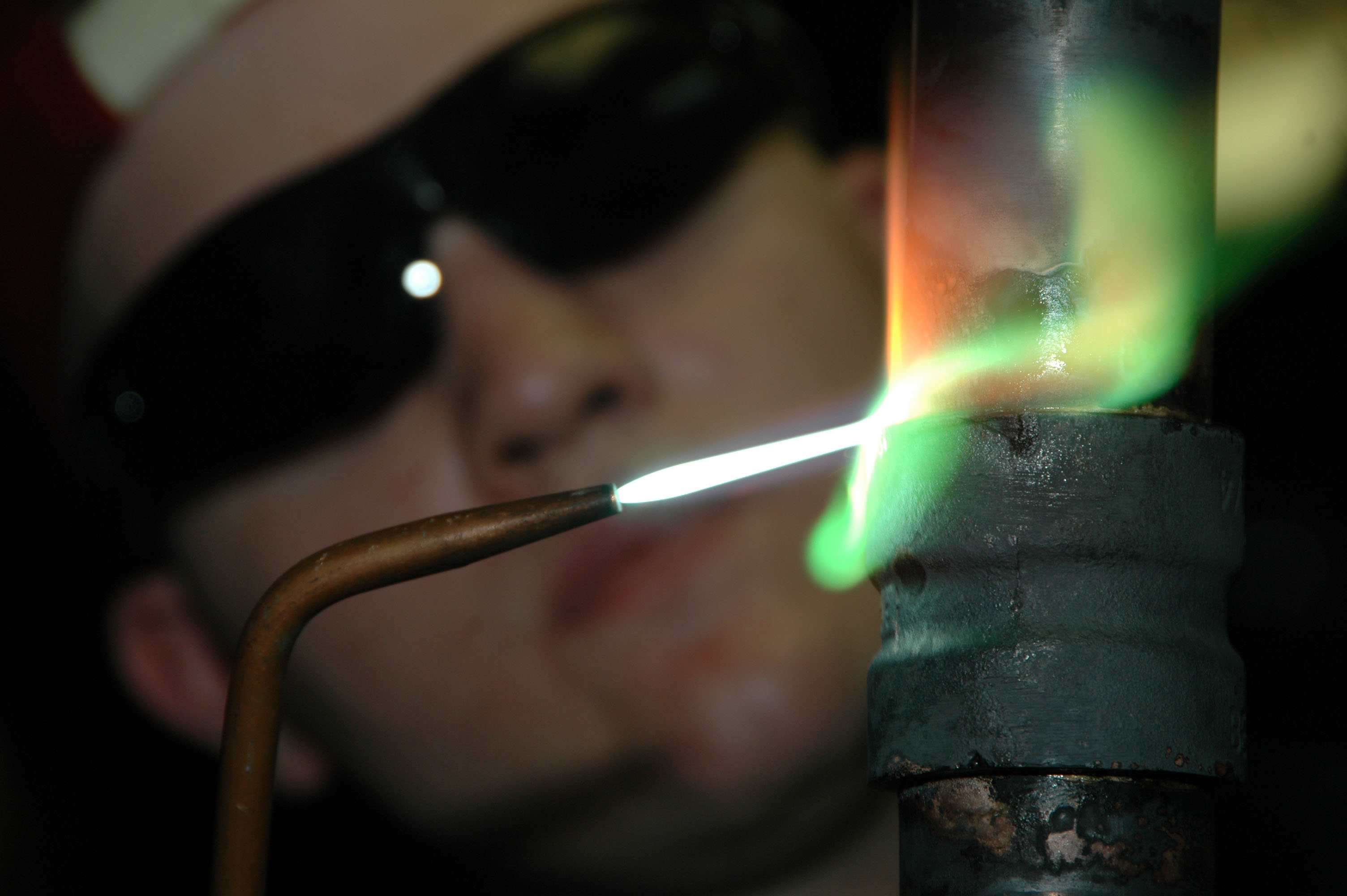
Technician brazing a copper-nickel pipe joint with a torch
Brazing

Close-fitting tubular assembly

Uniform heat, wettable surfaces, filler access, capillary path and hot clearance determine whether the interface fills.

U.S. Navy / Adam York, public domain, via Wikimedia Commons.
Technician soldering electronic components onto a printed circuit board
Soldering

Conductive connection and controlled rework

Alloy, finish, flux, thermal profile, solder volume, cleanliness and strain relief govern the connection.

Tlapicka, CC BY-SA 3.0, via Wikimedia Commons.
Performance reality

There is no universal strength ranking.

Joint capacity follows the complete material–geometry–process–load–environment system. A process reputation cannot replace design allowables and representative evidence.

Strength and load path

Welding is commonly the first candidate for a primary structural path because the joint can act as an integral continuation of the assembly and mature structural, piping, pressure and product-specific rules exist. That does not guarantee strength: penetration, weld size, toe geometry, residual stress, discontinuities, heat-affected properties and cyclic loading can still control failure.

A brazed joint can carry substantial load when compatible materials, filler, overlap, hot clearance and service are engineered together. Broad lap or scarf joints distribute load across a bonded area and usually favor shear. Peel and edge stress are damaging. Solder normally serves lower mechanical duty, but terminals and pads still fail when strain relief, creep, vibration or thermal expansion are ignored.

Do not quote bulk filler tensile strength as joint allowable strength.

Tension, lap shear, peel, bending, fatigue, creep, impact, vibration, pressure and leak integrity answer different questions. Test the loading mode that the actual joint will see.

Heat, distortion and service temperature

Fusion welding can create a fusion zone, heat-affected zone, steep thermal gradients, residual stress and distortion. Brazing and soldering avoid base-metal melting, which can reduce some dilution and distortion problems, but they are not heat-free. Their cycles can anneal cold-worked parts, overage precipitation-hardened alloys, damage coatings, demagnetize components, grow brittle reaction layers or move precision dimensions.

Peak temperature alone does not rank total thermal exposure. A whole assembly may spend significant time in a brazing furnace, while a focused resistance or laser weld can affect a much smaller region. Service limits require properties at temperature, creep, cyclic aging, oxidation, galvanic behavior and remelt risk in later operations—not just the joining temperature.

Dissimilar metals, corrosion and leak tightness

Brazing often deserves early evaluation for compatible dissimilar pairs because the base materials remain solid and dilution can be limited. Copper-to-steel and carbide-to-steel are common examples. Yet wetting, brittle compounds, thermal-expansion mismatch, filler erosion, galvanic corrosion and service temperature can still make a pair unsuitable. Plating, a diffusion barrier, ductile interlayer or transition insert may be required.

Both welding and brazing can create leak-tight assemblies. The choice depends on pressure or vacuum, fluid, vibration, permeation, corrosion, cleanliness, allowable leak rate, access and the governing code. Brazing is efficient for close-fitting tubes, manifolds and heat exchangers; welding is often required or preferred for direct structural continuity and specified pressure boundaries.

Eight-step selection framework

Define the requirement before naming the process.

This order prevents a supplier quote from being built around a familiar torch, filler or machine instead of the joint’s real failure consequence and acceptance evidence.

01

Define function and consequence

Structural, pressure-retaining, leak-critical, conductive, thermal, cosmetic or serviceable—and what happens if it fails.

02

Quantify every load

Tension, compression, shear, peel, bending, impact, fatigue, vibration, sustained load, pressure and handling.

03

Describe the environment

Temperature and cycles, pressure or vacuum, fluid, corrosion, humidity, cleanliness, outgassing and design life.

04

Lock the exact materials

Grade, temper, heat treatment, thickness, coating, plating, oxide condition, previous repair and allowed substitutions.

05

Design for the process

Butt, groove, fillet, lap, scarf, tubular, pad or terminal geometry with access, vents, fixtures and tolerance.

06

Set the thermal budget

Protect electronics, seals, magnets, finishes, heat-treated properties, dimensions and previously joined interfaces.

07

Compare production economics

Fixtures, takt time, simultaneous joints, consumables, cleaning, automation, inspection, rework and scrap.

08

Specify qualification evidence

Applicable code and edition, procedure and personnel qualification, inspection extent, tests and acceptance criteria.

Interactive planning aid

Choose a practical starting route.

Select the closest conditions. The recommendation is a planning screen, not design approval or a substitute for the governing code.

Planning recommendation

Start with welding

A qualified welding route is the normal first screen for a direct structural load path in compatible steel or stainless parts. Confirm grade, joint detail, fit-up, heat input, fatigue class and inspection.

Welding fit
88 / 100
Brazing fit
42 / 100
Soldering fit
18 / 100
Design aroundWeld size, penetration, edge preparation, load path and distortion control.
Validate withProcedure qualification, representative joints and the required NDT or mechanical test.
Main watch-outHeat-affected properties, cracks, lack of fusion, residual stress and fatigue-sensitive details.
Next decisionName the exact welding process and governing standard before requesting production pricing.
Application matrix

Match the route to the assembly—not the industry label.

The same factory may weld its frame, braze its heat exchanger and solder its controls. Start with these routes, then verify the exact grade, joint and service.

Welding

Structural steel frame or machinery base

Why it often fits: direct load transfer and established design, qualification and inspection routes. Verify grade, weldability, fatigue, preheat, distortion, WPS/PQR, personnel qualification and NDE.

Brazing

HVAC/R or heat-exchanger tube joint

Why it often fits: tubular geometry and capillary fill support repetitive leak-tight interfaces. Verify pressure, fluid, code, purge, cleanliness, filler, flux, vibration and leak test.

Soldering

PCB, connector or component lead

Why it often fits: conductive joining at controlled thermal exposure with scalable reflow, wave and selective routes. Verify product class, alloy, finish, flux, profile, voiding, residue and rework limits.

Brazing

Carbide tip on a steel tool

Why it often fits: joins dissimilar materials and distributes load over a designed overlap. Verify carbide grade, wetting, residual stress, ductile interlayer, service heat, impact and bond coverage.

Brazing / review

Thin precision or dissimilar-metal assembly

Why it often fits: base materials remain solid and overlap can limit dilution. Verify hot clearance, filler reaction, expansion mismatch, corrosion and the direction of joint load.

Process-dependent

Pressure boundary or field repair

Why it needs review: welding and brazing may both be technically viable within specific scopes. Original design, failure cause, code, access, contamination, qualified repair and repeat acceptance testing control the route.

Material compatibility

The alloy can change the answer before the equipment does.

“Metal” is not a usable purchasing specification. Grade, temper, thickness, coating, oxide, heat treatment and the second material in the joint can change weldability, wetting, filler selection and the allowable thermal cycle.

Material groupWelding screenBrazing or soldering screenQuestions for the RFQ
Carbon and low-alloy steel Often suited to welding, but carbon equivalent, hardenability, hydrogen, thickness, restraint, preheat, interpass temperature and postweld requirements can control the route. Brazing can join thin, precision, dissimilar or heat-sensitive steel assemblies without melting the base steel. Coatings and oxides must permit wetting, and service temperature must suit the filler system. Exact grade and condition; thickness range; coating; fatigue or impact duty; maximum hardness; corrosion protection; applicable structural, pressure or product code.
Stainless steel Fusion welding is common, but heat input, shielding, distortion, sensitization, ferrite balance, surface contamination and postweld cleaning can affect corrosion and service performance. Brazing can support thin assemblies and multiple joints, yet filler chemistry, atmosphere or flux, joint clearance and galvanic behavior require control. Soldering normally needs a finish or flux system that overcomes the passive surface. Stainless grade; service fluid and temperature; corrosion class; appearance requirement; cleaning/passivation; magnetic or vacuum constraints; permitted filler constituents.
Aluminum alloys Oxide removal, shielding, porosity control, hot-cracking sensitivity, filler selection and loss of temper near the joint are central. Not every high-strength alloy is readily fusion welded. Aluminum brazing depends on a suitable alloy combination, controlled clearance, oxide-management route and thermal cycle. The assembly may see broad heating even though the base metal does not melt. Alloy and temper on both parts; cladding; section thickness; prior heat treatment; leak requirement; post-join heat treatment; distortion limit; corrosion environment.
Copper and copper alloys High thermal conductivity can demand concentrated heat and careful process selection. Alloying elements, reflectivity, shielding, porosity, heat sinking and electrical-conductivity targets matter. Brazing is widely screened for tube, manifold and electrical assemblies because capillary geometry can produce repeatable interfaces. Soft soldering is common for electrical or light-duty connections where service temperature allows. Alloy designation; conductivity target; oxygen content; tube or busbar geometry; pressure/leak rate; joint temperature in service; atmosphere/flux cleanliness; electrical resistance limit.
Carbides, ceramics and dissimilar pairs Direct fusion may be impractical or may form brittle phases, severe residual stress or cracking. A transition insert, interlayer, solid-state process or a different joint concept may be necessary. Brazing often becomes the first evaluation route for carbide-to-steel and selected metal-to-ceramic assemblies because a designed overlap and compatible filler can manage the interface. Metallization or an active filler may be required. Exact material pair; coefficient-of-expansion mismatch; surface preparation or metallization; shock and impact; bond area; peak service heat; allowable reaction layer; qualification coupon geometry.
Plated, coated or heat-treated parts The joining cycle can vaporize a coating, create porosity, contaminate a weld pool, reduce local hardness or damage a finish. Coating removal and restoration may be part of the process plan. A coating may help wetting, block wetting or dissolve into the filler. Furnace or torch exposure can change temper, dimensions, magnets, seals and previously completed joints. Coating identity and thickness; restricted substances; heat-sensitive components; property retention; cosmetic zone; cleaning limits; sequence of joining, heat treatment and finishing.

Engineering checkpoint: compatibility charts are screening aids, not qualification evidence. Confirm the exact production material condition and representative joint geometry before releasing drawings, tooling or volume pricing.

Joint design rule

Do not reuse the same drawing for all three methods.

Geometry is part of the joining process. If a supplier proposes a process substitution, require a marked-up joint detail and a written validation plan—not only a new filler name.

  • Welding: control edge preparation, root opening, mismatch, penetration, weld size, access, sequence and shrinkage.
  • Brazing: control overlap, clearance at brazing temperature, capillary path, filler placement, vents, fixtures and residue-cleaning access.
  • Soldering: control wettable area, solder volume, pad or terminal geometry, component heat limits, inspection access and strain relief.

Welded T / fillet concept

Specified weld size and fusion create the direct path. A visible bead alone does not prove penetration or acceptable discontinuities.

Brazed lap concept

Designed overlap and hot clearance create bonded area. Zero gap and open gap are both unsafe assumptions.

Soldered terminal concept

The soldered interface provides electrical and mechanical connection, while support and strain relief protect against peel and cyclic movement.

Defects and verification

Inspect the hidden failure mode—not only the visible fillet.

Each process can look attractive from the outside while a function-critical defect remains at the interface. Inspection must match material, geometry, consequence and the governing acceptance criteria.

ProcessTypical defects or failure modesLikely contributorsUseful verification
WeldingCracks, lack of fusion or penetration, porosity, inclusions, undercut, burn-through, distortion and heat-affected-zone damage.Wrong procedure, contamination, poor fit, shielding loss, hydrogen, excessive restraint, unsuitable material or uncontrolled heat input.Visual testing plus specified PT, MT, RT, UT, eddy current, leak, mechanical or metallographic examination.
BrazingNonwetting, incomplete fill, voids, cracks, flux entrapment, erosion, dissolution, blocked passages and movement during cooling.Dirty or oxidized surfaces, wrong hot gap, uneven heating, incompatible filler, degraded flux, poor atmosphere or overheating.Process records, visual and leak testing, radiography where suitable, sectioning, metallography and destructive qualification coupons.
SolderingNonwetting, dewetting, insufficient solder, bridges, voids, disturbed joints, residue, pad damage, brittle interfaces and thermal fatigue.Poor solderability, wrong profile, contamination, excessive rework, flux mismatch, movement, weak support or thermal-expansion stress.Visual/AOI, X-ray for hidden joints, electrical and functional tests, cleanliness measurement, microsection and cycling tests.

ISO 18279 notes that some brazing imperfections cannot be established by nondestructive examination alone; acceptance and test extent must be defined for the application.

Close-up of brazing filler flowing around a prepared copper tube joint
Brazing process control

Capillary action cannot rescue a contaminated or badly fitted joint.

Oil, heavy oxide, an incompatible finish or uncontrolled heating can prevent wetting. Flux can help dissolve and exclude oxides, while vacuum or controlled atmosphere provides another route for selected material systems. Flux is common, but it is not universal.

Check clearance at temperature

Different expansion rates can open or close the operating gap compared with the room-temperature measurement. “As tight as possible” is not a design rule: too little clearance can block flux and filler; too much can weaken capillary action and increase reliance on the filler.

Specify the complete cycle

  • Exact base materials, plating, surface finish and cleaning sequence.
  • Filler designation, form, placement and approved substitutions.
  • Flux type or atmosphere, heating uniformity and working range.
  • Fixture, venting, cooling, residue removal and leak or section tests.
Photo: Le plombier du désert, CC BY-SA 4.0, via Wikimedia Commons.
Total assembly economics

Compare the cost of control, not only the cost of heat.

The cheapest filler or fastest demonstration can become the most expensive production route when fit, cleaning, distortion, inspection, scrap and repair are included.

Preparation

Fit, surfaces and fixtures

Welding may need edge preparation and restraint. Brazing needs repeatable close clearance and wettable surfaces. Soldering depends on finish, paste or flux control and component placement.

Process

Equipment and cycle

Compare manual power sources, robotic cells, induction stations, controlled-atmosphere furnaces, reflow lines, changeovers, utilities and real takt time.

Quality

Inspection and traceability

Include qualification coupons, NDT or X-ray, leak testing, microsection, process records, filler traceability and destructive sampling—not only operator time.

Losses

Distortion, cleaning and rework

Postweld straightening, flux-residue removal, coating restoration, failed leak tests, pad damage, furnace scrap and repeat inspection can dominate unit cost.

Automation follows joint repeatability.

Robotic arc, resistance and laser welding suit repeated paths; induction or furnace brazing can complete many interfaces in a controlled cycle; reflow, wave and selective soldering scale dense electrical assemblies. None of them compensates for unstable materials, fit or incoming surface condition.

Safety and compliance

All three are hot-work processes with material-specific hazards.

Hazards depend on the base material, coating, filler, flux, shielding or furnace atmosphere, cleaning chemistry and work location. “Lead-free” does not mean fume-free, and a familiar process name does not define the ventilation requirement.

Identify constituents

Review zinc, cadmium, lead, chromium, nickel, fluoride fluxes, oils, paint and cleaning residues before heating.

Capture at the source

Use task-specific local exhaust or ventilation based on the process, plume and exposure assessment.

Control hot work

Address ignition, cylinders, electrical energy, nearby combustibles, burns, arc radiation and confined spaces.

Match PPE to the hazard

Eye, face, skin and respiratory protection must match the wavelength, radiation, fume and chemical exposure—not a generic label.

Buyer checklist

What to include in a joining RFQ.

Send measurable requirements and a controlled drawing. Ask the supplier to identify assumptions, required joint changes, procedure evidence and acceptance limits in writing.

Materials

Grades, tempers, thicknesses, heat treatments, plating, coatings and permitted substitutions.

Controlled joint detail

Groove or overlap, gap or clearance, insertion, weld size, tolerance, access, vent and fixture datums.

Loads and consequence

Static, fatigue, impact, vibration, peel, shear, pressure, handling and failure consequence.

Service environment

Temperature, cycles, fluid, pressure or vacuum, corrosion, cleanliness, conductivity and design life.

Process materials

Filler and form, flux or atmosphere, shielding or purge, certificates and prohibited substances.

Standards and edition

Construction code, customer specification, product regulation and exact contract edition.

Qualification and inspection

WPS/BPS, personnel qualification, NDT extent, leak or mechanical tests, sampling and acceptance.

Production and records

Volume, takt, fixtures, automation, traceability, process charts, repair rules, packaging and ramp plan.

From comparison to a qualified sample

Validate the real material, joint and acceptance target.

For a laser-welding route, Oceanplayer can review the part geometry, material, thickness, gap, production target and required evidence before recommending a handheld or automated configuration.

Send these details first
  • Material grade, thickness and coating
  • Joint drawing, gap range and fixture access
  • Load, leak, appearance or penetration target
  • Daily volume and target cycle time
  • Required inspection or test evidence
Frequently asked questions

Welding vs brazing vs soldering FAQ

Short answers to the questions that most often distort process selection.

What is the main difference between welding, brazing and soldering?

Welding creates coalescence through heat, pressure or both. Fusion welding melts base material locally, while solid-state welding does not. Brazing and soldering leave the base materials unmelted and use a separate filler. Under the conventional AWS/ISO terminology, brazing filler has a liquidus above about 450°C and solder filler is at or below that boundary.

Which is stronger: welding, brazing or soldering?

There is no universal ranking. Welding is commonly selected for primary structural paths, brazing can carry substantial load through a properly designed bonded area, and soldering normally serves lower mechanical duty. Materials, geometry, loading mode, defects, fatigue, creep, corrosion and service temperature determine the result.

Does welding always melt the base metal?

No. Fusion welding processes melt base material locally, but friction, diffusion, ultrasonic and other solid-state welding processes join without base-metal melting. Name the actual process rather than treating “welding” as one molten-pool method.

Why is 450°C used to separate brazing from soldering?

It is a terminology boundary based on the filler metal’s liquidus. It does not state joint strength, torch or iron setting, workpiece temperature, or allowable service temperature. The contract should identify the applicable standard and unit convention.

Can a brazed joint be as strong as a welded joint?

A brazed joint can meet substantial structural requirements in a suitable design, but the comparison must use the actual materials, overlap, clearance, filler, load direction, interface quality and service. A brazed lap and a welded butt joint distribute stress differently, so generic strength labels are misleading.

Can brazing join dissimilar metals?

Often, yes. Because the base materials remain solid, brazing can limit dilution and join combinations such as copper to steel or carbide to steel. The engineer must still verify wetting, filler reactions, expansion mismatch, brittle phases, galvanic corrosion and properties at service temperature.

Which process causes the least distortion?

Soldering often has the lowest temperature in typical use and brazing avoids base-metal melting, but no universal ranking covers every heat source. A focused laser or resistance weld may affect a smaller region than broad torch or furnace heating. Compare the actual time-temperature cycle, fixtures, geometry and material response.

Do brazing and soldering always require flux?

No. Flux is common because it helps control oxides and promote wetting, but vacuum, inert or reducing atmospheres, controlled-atmosphere processes, specialized finishes and selected material-specific filler systems provide alternatives. The procedure must define how wettable surfaces are achieved.

Can I change a welded joint to brazing or soldering without redesign?

Usually not. Brazing often needs overlap, controlled hot clearance, a capillary path, vents and filler access. Soldering needs wettable area, controlled solder volume, thermal access and strain relief. A process change requires a drawing review and representative validation.

Technical references

Standards and primary guidance used in this guide

Always confirm scope, edition and contract precedence for the actual product. Vocabulary and defect classifications do not by themselves qualify a procedure or approve a design.

  1. AWS A3.0M/A3.0:2025 — Standard Welding Terms and Definitions.
  2. AWS Brazing & Soldering Manufacturers Committee — definitions, wetting, filler classification and application overview.
  3. AWS Brazing Handbook, Chapter 1 preview — brazing principles, capillary action and process fundamentals.
  4. ISO 857-2:2005 — soldering and brazing process vocabulary.
  5. ISO 17672:2024 — brazing filler metals and designation.
  6. ISO 18279:2023 — classification of imperfections in brazed joints.
  7. AWS B2.2/B2.2M:2026 — brazing procedure and performance qualification.
  8. AWS B2.3/B2.3M:2026 preview — industrial soldering qualification scope and exclusions.
  9. OSHA Welding, Cutting and Brazing: Hazards and Solutions — fume, radiation, fire and electrical hazards.
  10. OSHA 29 CFR 1910.252 — ventilation, hot-work and material-specific requirements.