

Can Brass Be Laser Welded?
Yes—brass can be laser welded, but zinc evaporation, high reflectivity and rapid heat flow make it less forgiving than steel. This guide explains alloy selection, laser source choices, porosity and cracking control, fumes, joint design, filler wire and the tests that should happen before production.
Four decisions before the first test weld
Start with the alloy, then control zinc vapor, match the laser to the absorption challenge and design extraction around the real joint. These four checks define whether a brass application deserves a structured welding trial.
Lower-zinc grades are generally easier, but even CuZn37 can be welded with a qualified process.
Vapor pressure can destabilize the keyhole, eject melt and leave pores below an attractive top bead.
Source wavelength, beam profile, travel speed, wobble and focus must create a stable energy window.
Brass welding can generate zinc oxide fume; safety controls must be designed for the actual process.
When is laser welding brass a good idea?
Laser welding is most attractive when a brass part needs a small heat-affected zone, a precise seam, localized energy delivery or automation. Typical candidates include electrical contacts, sensor housings, fittings, small hardware, decorative assemblies, instrument parts and brass-to-steel subassemblies. Thin or compact components can benefit because the beam can place energy into a much smaller region than many conventional joining methods.
The process is less attractive when the alloy is unknown, the material contains lead, the joint traps vapor, the parts have inconsistent gaps, the weld is purely decorative and can be brazed at lower temperature, or the factory cannot install effective laser and fume controls. A visually smooth bead alone is not proof of quality: zinc-driven pores and solidification cracks may sit below the surface.
What does a successful brass laser weld look like?
A good result is not simply “gold colored.” It has stable penetration for the joint requirement, limited underfill, controlled zinc loss, no unacceptable pore population, no crack network, repeatable bead geometry and a surface condition that meets the drawing. The inspection plan may include a polished cross-section, radiography or CT for critical work, leak testing, tensile or peel testing, dimensional checks and production monitoring.
Is a handheld fiber laser welder suitable for brass?
A 1064 nm handheld fiber laser may weld selected brass applications, especially after a coupon test proves that the source, beam motion, wire, travel speed and joint can form a stable seam. However, brass is copper rich and can reflect near-infrared energy strongly before melting. High-zinc or highly reflective parts may need a narrower operating window than steel, and some jobs may favor a green-wavelength or specialized beam-profile system instead of a standard handheld configuration.
Why is brass harder to laser weld than steel?
Brass combines a reflective copper-rich surface with zinc, a volatile alloying element. The beam must initiate a stable melt while preventing vapor pressure from disrupting the keyhole and changing the local composition.
The temperature mismatch
Approximate reference temperatures for understanding the process—not a production setpoint.
Low initial absorption
Near-infrared fiber lasers can couple poorly into a cold copper-rich surface. Absorption changes rapidly after melting, so the transition can be abrupt.
Zinc vapor pressure
Vapor leaving the molten pool can cause spatter, underfill, an unstable capillary and pores trapped during solidification.
Fast heat flow
Copper-rich alloys conduct heat away quickly, so power, spot size and travel speed must create fusion without an excessive local peak.
Composition changes
Preferential zinc loss can alter weld color and local chemistry. Leaded grades add a serious fume and metallurgical concern.
Which brass grades are easier to laser weld?
Weldability usually narrows as zinc and free-machining additions increase, but alloy composition is only one part of the decision. The table is a relative screening guide, not a replacement for a material certificate and test weld.
| Brass family | Typical composition direction | Relative laser-welding fit | Main process concern | Recommended next step |
|---|---|---|---|---|
| Red brass / gilding metal | About 5–15% zinc, copper rich | More favorable | Reflectivity and heat conduction remain important | Establish focus, speed and shielding on coupons |
| Cartridge brass (such as CuZn30) | About 30% zinc | Controlled test | More zinc vapor and possible underfill or porosity | Compare source, beam motion and joint venting |
| Yellow brass / CuZn37 | About 35–37% zinc | Narrower window | Keyhole instability, spatter and internal pores | Use a structured parameter matrix and cross-sections |
| Leaded free-cutting brass | High zinc plus lead addition | Specialist review | Lead-containing fume, cracking and composition control | Pause until alloy and EHS controls are professionally assessed |
| Unknown or plated brass | Unverified base alloy or coating | Do not guess | Unknown fumes, coating reactions and unstable results | Identify alloy and coating before any laser trial |
Is your brass part a reasonable laser-welding candidate?
This quick screen helps organize the next conversation. It does not qualify a weld or replace a safety review.
Describe the application
Choose the closest known conditions. Unknown material should always lead to identification and testing first.
A controlled brass laser-welding trial is reasonable.
Start with a coupon matrix and inspect below the surface before confirming machine configuration.
Green vs 1064 nm, pulsed vs CW: which is better for brass?
No laser type wins every brass application. Wavelength affects initial coupling, while pulse format, beam profile, focus and motion determine how energy reaches the joint.
| Laser direction | Why it may help | Typical candidate | Main limitation | What to compare in a trial |
|---|---|---|---|---|
| 515 nm green laser | Higher absorption in copper-rich materials can improve energy coupling and process initiation | Thin, reflective or precision copper-alloy parts | Specialized system cost and availability | Start stability, spatter, penetration and zinc loss |
| 1064 nm pulsed fiber / solid-state | Pulse energy and timing can localize heat on small parts | Micro-welds, thin sections and discrete joints | Peak intensity can eject material if poorly controlled | Pulse overlap, energy, focus, crater and pore level |
| 1064 nm CW fiber laser | Efficient continuous seams and broad industrial availability | Longer seams and production parts after qualification | Low cold-state absorption and abrupt coupling transition | Power ramp, beam wobble, speed and keyhole stability |
| Core-and-ring / adjustable beam | Redistributes energy to stabilize the melt and keyhole | High-zinc brass and demanding deep-penetration development | Specialized optics and process engineering | Ring/core balance, spot size, seam surface and CT porosity |
Prioritize controllability
Pulsed energy or a better-absorbed wavelength may create a wider stable window, but the pulse must not cause zinc-rich ejecta or burn-through.
Control the transition
For CW fiber welding, examine power ramping, focus, wobble and travel speed so the process does not jump from reflection to excessive penetration.
Test the real joint
A handheld machine should be assessed with the actual fixture, operator motion, wire, gas, extraction and access angle—not a flat plate alone.
What causes porosity, cracking and discoloration in laser-welded brass?
Treat each defect as evidence about melt flow, vapor escape, energy distribution and cleanliness. Do not respond to every problem by simply increasing power.
Porosity and pinholes
Zinc vapor can become trapped as the pool closes. Lap interfaces, unstable keyholes and an abrupt stop increase risk.
- Check joint venting and beam position
- Review speed, ramp-down and focal position
- Section the weld; do not judge only the surface
Hot cracking
Composition changes, thermal strain, restraint and an unfavorable solidification path can produce cracks at the centerline or grain boundaries.
- Confirm alloy and lead content
- Reduce unnecessary peak heat and restraint
- Evaluate suitable filler and beam distribution
Underfill and spatter
Violent evaporation can eject molten metal and leave a depressed seam. Excessive peak intensity is a frequent contributor.
- Review spot size and wobble width
- Stabilize coupling instead of adding power
- Use wire only after the root cause is understood
Black or white residue
Oxide deposits can reflect high heat, inadequate shielding or zinc-rich vapor condensation. Color is a clue, not a complete diagnosis.
- Verify gas coverage and nozzle position
- Inspect extraction direction versus shielding
- Review surface chemistry and heat input
Lack of fusion
Reflectivity, off-focus delivery, excessive speed or poor access can prevent a consistent melt even when the surface looks heated.
- Confirm beam location and working distance
- Measure penetration on a cross-section
- Check whether the source suits the alloy
Unstable bead width
Variable gaps, manual motion, surface finish or rapidly changing absorption can make the seam alternate between conduction and keyhole behavior.
- Improve fixturing and edge consistency
- Record power, speed and wobble together
- Consider automation for repeat production
How should brass laser-welding parameters be developed?
There is no responsible one-line recipe based only on thickness. Develop a window with the actual alloy, joint and acceptance test while monitoring defects below the surface.
| Variable | If too low or narrow | If too high or wide | What to verify |
|---|---|---|---|
| Laser power / pulse energy | Lack of fusion, inconsistent initiation | Spatter, underfill, zinc loss, burn-through | Penetration, seam depression and internal pores |
| Travel speed | Excess heat per length and vaporization | Insufficient fusion and discontinuous seam | Line energy, bead continuity and heat-affected area |
| Spot size / focus | High intensity and unstable ejection | Low energy density and shallow fusion | Working distance, actual focus and depth of fusion |
| Wobble width / frequency | Narrow bead with limited gap tolerance | Shallow, overly wide or overheated surface | Bead profile, sidewall fusion and dwell distribution |
| Shielding gas | Oxidation and poor melt-pool protection | Turbulence that disturbs shielding or vapor flow | Nozzle distance, flow pattern and residue |
| Joint gap / vent path | Trapped vapor in some lap configurations | Underfill, misalignment and lack of bridging | Joint-specific cross-section—there is no universal gap |
| Wire feed | Insufficient gap filling where filler is required | Cold wire, excessive reinforcement or instability | Wire alloy, feed position, dilution and joint strength |
Lock the material identity
Record alloy designation, zinc content, lead content, coating, thickness and surface condition.
Define the joint acceptance
Specify penetration, load, leak requirement, appearance, allowable pores and inspection method.
Run a parameter matrix
Change one controlled variable at a time and record power, speed, focus, wobble, gas and wire.
Inspect beyond the top bead
Use cross-sections and the relevant mechanical, leak or nondestructive test before release.
Fit-up can matter as much as laser power
Vapor needs a controlled escape path, but the joint also needs enough metal to form a sound seam. The best geometry is the one proven on the actual assembly.
Keep alignment repeatable
Tight, consistent edges reduce bead variation. A deliberately introduced gap may help some vapor conditions but can also cause underfill; qualify it instead of using a universal 0.1–0.2 mm rule.
Do not trap zinc vapor
Vapor generated at an interface can build pressure. Review beam offset, venting strategy, overlap, clamp position and whether another joint style is safer.
Protect the edge from collapse
Open access helps vapor escape, but thin edges can melt back quickly. Fixtures, beam angle, focus and reduced peak intensity become important.
Use wire for a defined reason
A suitable copper-based or silicon-bronze filler can bridge a gap or adjust seam chemistry, but it also changes dilution and joint properties. Confirm compatibility with the part specification.
Protect without creating turbulence
Argon is a common starting point; helium or blends may be evaluated for selected applications. Flow must match nozzle geometry, access and vapor direction.
Remove oil and unstable coatings
Oil, oxide, plating and shop contamination affect absorption, fumes and porosity. Use a controlled cleaning method and keep the joint dry before welding.
Brass welding needs engineered controls—not just an open door
Heating zinc-containing alloys can generate zinc oxide fume associated with metal fume fever. Leaded or coated brass may introduce additional hazards. Control the plume at its source and complete the required Class 4 laser safety planning.
Confirm the alloy and coatings before testing. Free-machining brass can contain lead, and old decorative parts may carry plating or residues that change both fume composition and weld behavior.
Capture fume close to the source
Use local exhaust designed for the plume and positioned without pulling shielding gas away from the weld.
Assess exposure with qualified support
Ventilation capacity and respiratory protection must follow the actual alloy, production rate, enclosure and local regulations.
Control Class 4 laser hazards
Plan enclosure or controlled area, interlocks, wavelength-specific eye protection, reflective surfaces, training and emergency procedures.
Verify extraction during production
Commission the system, inspect filters and ducts, and confirm that fixture or nozzle changes do not move the plume outside the capture zone.
When should you braze, solder or resistance weld instead?
The best process is the one that meets the joint requirement with the lowest total risk and cost. Laser fusion is not automatically the best choice for every brass assembly.
| Joining method | Often a good fit for | Strength direction | Main trade-off | Choose it when |
|---|---|---|---|---|
| Laser welding | Precise seams, automation, low distortion, compact heat input | Fusion joint when qualified | Zinc vapor, reflectivity, safety system and process development | The seam requires precision or throughput and can be properly validated |
| TIG brazing / silicon bronze | Decorative, high-zinc or gap-sensitive assemblies | Filler-bonded joint rather than full base-metal fusion | More visible filler and skilled manual work | Lower base-metal temperature reduces the reason to boil zinc from the brass |
| Soldering | Electrical, plumbing and lightly loaded thin parts | Lower-temperature, lower-strength joint | Not suitable for high structural or temperature demands | Joint loading is modest and cost simplicity matters more than fusion |
| Resistance welding | Overlapping strips, contacts and localized spots | Localized spot or projection joint | Electrode access, marks and limited continuous-seam capability | High-volume spot joining is more important than a continuous seam |
| Mechanical fastening / adhesive | Heat-sensitive, dissimilar or serviceable assemblies | Depends on fastener or adhesive design | Added components, cure time or joint size | Heat and fume risk outweigh the value of a welded joint |
A convincing result needs more than a beautiful top bead
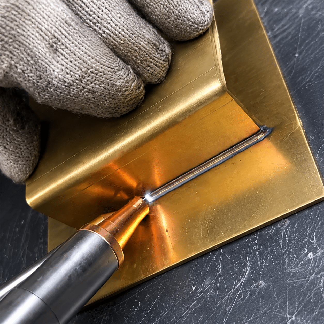
These Oceanplayer application images illustrate the kinds of evidence a welding trial should capture. Your brass test should be labeled with alloy, thickness, settings and inspection results.


Watch the process—then request a brass-specific test.
Review the welding process, torch movement, joint preparation and finished seam. For brass welding, send the exact alloy, thickness, joint design and inspection target so the sample test can focus on zinc vapor, porosity and crack control.
Prove the brass weld before choosing a machine.
Share the alloy certificate, thickness, joint drawing, seam length, production volume and acceptance requirement. Oceanplayer can help identify the right test direction and machine configuration.
Identify
Confirm alloy, zinc, lead, coating, thickness and joint type.
Test
Compare laser direction, power, speed, focus, gas and wire.
Validate
Section, inspect and test the weld against the real requirement.
Related laser-welding machines, guides and engineering tools
Use these pages to compare machine configurations and quantify heat input, wire demand and shielding-gas planning before a sample test.
Brass laser-welding FAQ
Short answers to common buyer and engineering questions about fiber laser welding brass.
Can brass be laser welded?
Yes. Brass can be laser welded when the alloy is identified and the process controls reflectivity, zinc evaporation, joint fit-up, shielding, extraction and the required weld inspection. High-zinc or leaded grades require more cautious evaluation.
Can a fiber laser weld brass?
A 1064 nm fiber laser can weld selected brass applications, but cold brass absorbs near-infrared energy poorly and coupling can change rapidly after melting. A coupon test should confirm source compatibility, beam motion, focus, speed and internal weld quality.
Is a green laser better for welding brass?
Green wavelength around 515 nm is absorbed more effectively by copper-rich materials than conventional near-infrared light, which may improve process initiation and stability. It is not automatically superior for every joint; power, beam profile, thickness, speed and production cost still matter.
Why does laser-welded brass develop pores?
Zinc can vaporize before the copper-rich matrix fully melts. If that vapor is trapped as the pool solidifies, it leaves pores. Joint geometry, keyhole stability, travel speed, focus, ramp-down and vapor escape all affect the result.
Why does brass crack during laser welding?
Possible contributors include zinc loss, lead or other alloying additions, thermal strain, excessive restraint, unstable melt flow and an unfavorable solidification path. Confirm the alloy and inspect the crack location before changing parameters.
Does brass laser welding need shielding gas?
Most fusion-welding trials use an inert shielding strategy such as argon, with helium or blends considered for selected processes. The correct gas and flow depend on nozzle design, access, alloy, speed and required surface condition.
Does brass laser welding need filler wire?
Not every joint needs filler. Wire may help bridge controlled gaps, shape a cosmetic seam or adjust weld chemistry. The filler alloy, dilution and joint properties must be validated for the application.
Can you laser weld brass to stainless steel?
Dissimilar brass-to-stainless laser welding is technically possible, and published work has studied pulsed-laser joints. Different absorption, thermal conductivity, melting behavior and intermetallic formation make beam position and testing especially important.
What is the best power for laser welding brass?
There is no universal power value. Required power depends on alloy, zinc content, wavelength, pulse format, beam profile, spot size, thickness, joint, speed and penetration target. Treat any isolated power recommendation as incomplete until a sample is tested.
Are zinc fumes from brass welding dangerous?
Heating zinc-containing metal can create zinc oxide fume associated with metal fume fever. Identify the alloy, capture the plume with engineered local exhaust, assess worker exposure and follow applicable occupational-health and laser-safety requirements.
Should I laser weld or braze brass?
Choose laser welding when a precise fusion seam, low distortion or automation justifies the process-development and safety requirements. Brazing may be better for decorative, high-zinc or gap-sensitive parts that do not require full base-metal fusion.
How do I qualify a brass laser weld before production?
Confirm alloy and coatings, define acceptance criteria, develop a documented parameter window, section representative coupons and complete the mechanical, leak or nondestructive testing required for the actual component.
Technical references and safety sources
This guide translates published research and government safety guidance into buyer-friendly planning information. It does not provide a qualified welding procedure or site-specific safety design.
- Hugger et al., “Laser Beam Welding of Brass,” Physics Procedia 56 (2014) — CuZn37 keyhole behavior and zinc evaporation.
- Laser Zentrum Hannover, “Laser beam welding of brass with combined core and ring beam” (2023) — CuZn37/CuZn39Pb3 deep-penetration study.
- Fraunhofer, green 515 nm laser process study on copper — wavelength-coupling context for copper-rich materials.
- NIOSH Pocket Guide: Welding fumes — exposure routes, symptoms and occupational-health context.
- NIOSH Engineering Controls Database: Welding local exhaust ventilation — source-capture control guidance.