

What Are the Main Components of a Laser Welding Machine?
A laser welding machine is a coordinated system, not just a laser source. Its core architecture combines beam generation, beam delivery, focusing optics, motion or operator guidance, controls, cooling, shielding gas, extraction and laser-safety engineering. Optional wire feeding, seam tracking and process monitoring are selected around the joint and production requirement.
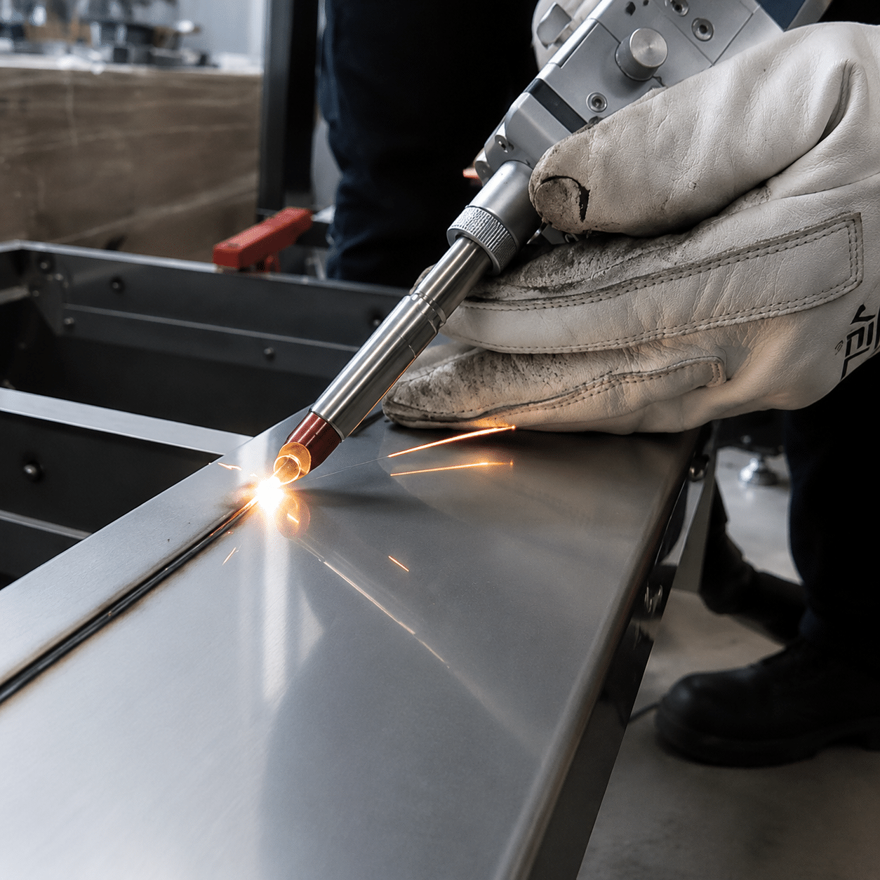
Ten functions make the system work.
The main laser welding machine components are the laser source and power electronics, beam delivery path, processing or welding head, motion and fixturing, control system, cooling system, shielding/process-gas supply, fume extraction, safety system and electrical infrastructure. A handheld welder packages some of these functions inside a mobile cabinet; an automated cell distributes them across a source cabinet, robot or axes, fixture, enclosure and control panel.
Wire feeders, seam trackers, cameras, weld-monitoring sensors and automated loading are not universal. They become valuable when joint gaps, position variation, traceability or production volume justify the added complexity.
Follow the energy from electricity to the weld.
The easiest way to understand a laser welder is to trace the process chain. Energy is generated and conditioned, guided to the head, focused on a controlled joint and protected by support systems. A failure anywhere in that chain can change weld quality or safe operation.
Laser source
Creates the beam and defines the available wavelength, power range, modulation and beam characteristics.
Optical path
Transfers the beam through a process fiber or free-space optics while preserving usable beam quality.
Welding head
Collimates, focuses and—when specified—oscillates or splits the beam at the workpiece.
Motion + fixture
Controls the relationship among beam, joint, filler wire and workpiece throughout the weld path.
Material interaction
Absorbed energy creates conduction or keyhole welding, depending on the qualified process window.
Which components are essential?
Every working system needs the functions in the “core” column, even when several are hidden in one cabinet. Optional modules are selected only when they solve a defined joint, quality or automation problem.
| Subsystem | Status | What it controls | Evidence to request |
|---|---|---|---|
| Laser source + power electronics | Core | Available optical power, modulation, beam characteristics and source diagnostics. | Rated output, operating modes, interface, warranty and service documentation. |
| Beam delivery + processing head | Core | Beam transmission, focal position, spot behavior and protection of the optical train. | Head rating, focal configuration, protective-window strategy and approved fiber routing. |
| Motion, guidance + fixturing | Core | Relative position, travel speed, torch angle, joint gap and repeatability. | Reach, accuracy/repeatability where relevant, fixture concept and dry-cycle proof. |
| Controls + HMI | Core | Recipes, timing, I/O, permissions, alarms, safe-state logic and production data. | Control narrative, user levels, alarm history, backup method and integration list. |
| Cooling + utilities | Core | Permitted temperature, flow, power quality and operating environment. | Utility schedule, coolant specification, heat load, ambient limits and alarms. |
| Shielding gas + fume control | Core | Weld atmosphere, optical cleanliness, plume behavior and worker exposure controls. | Material-specific trial, gas/nozzle arrangement and extraction risk assessment. |
| Safety architecture | Core | Accessible radiation, access, interlocks, emergency response and service boundaries. | Risk assessment, classification, safety circuit information and operating instructions. |
| Wire feed, seam tracking + monitoring | Application dependent | Gap accommodation, path correction, closed-loop control and quality evidence. | Representative sample test, false-call study and maintenance/consumables plan. |
The laser source creates a usable process beam.
The correct source is the one that creates a stable, controllable process window for the real material, joint and production target—not simply the highest wattage available.
What the source determines
- Wavelength: affects optical compatibility and material absorption behavior.
- Available power: sets the energy budget, but does not by itself guarantee penetration.
- Beam characteristics: influence the focused spot and energy distribution.
- Modulation: controls how optical output changes during starts, stops and travel.
- Diagnostics: support fault detection, service and process records.

Fiber-laser principle
A source contains its own optical and electrical architecture before the beam ever reaches the welding head.
Alex-engraver / Wikimedia Commons, CC0.Why source selection cannot be reduced to a thickness chart
Penetration and travel speed also depend on joint type, alloy, surface condition, focal position, spot size, beam oscillation, shielding, heat sinking and acceptance criteria. A “1,500 W equals a certain thickness” chart can be a starting hypothesis for one machine, but it is not a transferable guarantee.
Ask the supplier to show the same material grade, joint geometry, thickness, orientation and quality test that matter to your production—not a visually attractive bead on unrelated sample metal.
Beam delivery and the welding head define what reaches the joint.
The delivery path transports the beam; the processing head conditions and focuses it. The head may also add wobble, gas, wire guidance, coaxial vision, cross-jet protection or process sensors.

Processing head as an integration point
Optics, nozzle, sensor and mechanical interfaces must remain aligned, clean and thermally stable.
Pipimaru / Wikimedia Commons, CC BY-SA 3.0.Inside or around a welding head
- Collimation optics convert the delivered beam into a controlled optical path.
- Focusing optics create the required focal geometry at the workpiece.
- Protective window shields higher-value optics from spatter and contamination.
- Wobble scanner moves the spot in a defined pattern when the process requires a wider interaction zone.
- Nozzle and gas path deliver shielding or optical-protection flow near the process.
- Wire guide positions filler wire relative to the beam and joint.
- Camera or sensor port supports alignment, monitoring or measurement.
IPG notes that industrial welding heads can integrate real-time weld measurement; Laserline lists cameras and pyrometers among available processing-optics add-ons. These examples show why the head should be specified as a system interface rather than a generic lens holder.
Motion and fixturing are part of the welding machine.
A stable beam cannot compensate for a moving gap, a poorly located seam or inconsistent heat sinking. In many projects, the fixture and motion concept determine whether a promising laboratory weld becomes a repeatable production process.
Hand-guided motion
The operator controls travel speed, stand-off, angle and path. Training, nozzle design, physical access and work support become essential system components.
Linear or CNC axes
Useful for repeatable paths and dedicated fixtures. Axis range, acceleration, cable management and synchronization must suit the weld.
Robot or cobot
Adds reach and flexible path programming, but also demands tooling, safety integration, collision planning and process-cable management.
Fixture + seam control
Locates parts, manages gap and distortion, conducts heat and preserves access for gas, wire and extraction.
The source, head, motion and fixture must be commissioned together. Testing the laser on a loose coupon does not validate part loading, clamps, access, sequence, distortion or cycle time.
The support systems keep the weld stable and the workplace controlled.
Controls, cooling, gas and extraction are sometimes treated as accessories. In practice, they determine repeatability, uptime, optical cleanliness and safe operation.
Control system, HMI and recipe management
The control layer coordinates laser enable, power commands, motion, gas pre-flow/post-flow, wire feed, interlocks, alarms and production I/O. A strong implementation separates operator recipes from service settings, records important faults and provides a validated backup/restore process.
- Define who may select, edit, approve and export recipes.
- Confirm safe behavior when a sensor, gas supply, cooling circuit or communication link fails.
- Map external I/O before integration with robots, fixtures, conveyors or MES systems.
- Do not accept an HMI screenshot as evidence that safety functions have been validated.
Cooling and environmental control
The laser source, processing head and electronics have defined temperature and flow requirements. Some compact systems are air-cooled; others require a dedicated water chiller or factory cooling loop. The correct choice comes from the manufacturer’s heat-load, water-quality, ambient and duty-cycle specifications—not a universal “below or above 1 kW” rule.
Shielding gas, cross-jet and process air
Process gases can shield the molten metal, influence plume behavior and help protect optics, but one gas and one flow rate are not correct for every alloy, nozzle and weld. TWI distinguishes weld shielding, plasma control and plume control as different functions. Gas type, delivery geometry and flow must therefore be qualified with the material and head arrangement.
Fume extraction and filtration
Laser welding can generate airborne contaminants from the base metal, coatings, oil, plating and filler material. Capture should be designed from the material hazard assessment and real plume path. OSHA identifies local exhaust and mechanical ventilation requirements for welding conditions and specific metals; extraction should not disturb shielding or direct contamination into optics.
Safety architecture is a machine subsystem—not a pair of glasses.
Industrial welding lasers commonly contain or expose Class 4 radiation. The protection strategy must address direct and reflected beams, fire, fumes, electrical energy and the different hazards present during normal operation, setup and service.
What a safety system can include
- Protective housing or controlled area appropriate to accessible emission and the task.
- Interlocked doors and panels tied to a defined safe state.
- Key control, emission indication and reset logic suitable for the laser class and system design.
- Beam stop and reflection management for every credible beam path.
- Emergency-stop architecture integrated with laser, motion and supporting equipment.
- Access control, procedures and training for operation, alignment, cleaning and service.
- Material-specific fume and fire controls based on the actual work.
Enclosed and open-beam machines are not the same
An engineered, interlocked enclosure may allow a high-power laser to operate as a Class 1 system during normal production while preserving higher internal hazards during service. Open-beam handheld or special systems require a controlled-area strategy and site-specific controls. Therefore, “every laser welder must look like a sealed box” is too simplistic, but “eyewear alone is enough” is also unsafe.
OSHA’s laser guidance discusses protective housings, interlocks, remote connectors and controls for use without protective housing. ISO 11553-1:2020 covers laser-radiation safety requirements for laser-processing machines.
Build a first-pass component priority.
Select the closest production scenario. This does not design the safety circuit or qualify the weld; it identifies the subsystems that deserve early engineering attention.
Prioritize operator guidance and controlled-area safety.
For a handheld, high-mix system, usability, fiber routing, nozzle access, work support, training and a validated laser-controlled area matter as much as output power.
The same functions appear in different packaging.
Do not compare two suppliers by cabinet count. One unit may combine source, cooling and controls; another may separate them for serviceability or cell integration.
Handheld laser welder
Typically packages source, controls and cooling in a mobile cabinet, with a process fiber, handheld head, gas supply and optional wire feeder.
- Operator motion and ergonomics
- Open-beam safety strategy
- Fiber and cable protection
- Nozzle, lens and wire consumables
Fixed workstation
Combines a dedicated fixture with linear, rotary or CNC motion and may use an interlocked housing for repeatable parts.
- Axis range and synchronization
- Fixture datum and heat control
- Recipe permissions
- Part loading and enclosure access
Robotic welding cell
Adds robot control, positioners, safety integration, path programming, cable dress and often vision or monitoring.
- Reach and singularity study
- Tool center point stability
- Seam location and calibration
- Automation and line I/O
Add complexity only when it closes a measured gap.
Optional equipment should solve a documented cause of instability, quality risk or labor. Otherwise, it can add calibration, false calls, consumables and maintenance without improving the weld.

Application geometry drives integration
Large or rotational parts may require positioners, specialized shielding and custom access around the process head.
Barbara Nasiłowska / Wikimedia Commons, CC BY 4.0.When common add-ons earn their place
- Wire feeder: supports filler addition, joint-gap accommodation or composition control when a qualified procedure calls for it.
- Seam tracker: adjusts path where measured joint-location variation exceeds the acceptable beam-to-joint tolerance.
- Vision system: helps locate features, verify loading or guide path correction when contrast and access are suitable.
- Process monitor: records optical, acoustic, thermal or geometric signals that have been correlated to relevant process outcomes.
- Inline measurement: may estimate penetration or surface geometry, but must be validated against destructive or independent inspection.
- Part handling: reduces non-welding labor and stabilizes cycle time in repeatable production.
A monitoring system becomes useful only after its signal, limits, false-call behavior and reaction plan have been validated for the actual joint.
A complete machine extends beyond the laser cabinet.
For automated production, the “laser welding machine” often includes the cell enclosure, robot or axes, fixtures, extraction, safety PLC, power distribution and interfaces to the wider line.

Think in system boundaries
This industrial laser cutting installation is shown as an integration example: machine structure, motion, enclosure, extraction and utilities surround the optical process. A welding cell requires the same system-level thinking, configured for joining.
Metaveld BV / Wikimedia Commons, CC BY-SA 3.0.Specify functions and evidence—not a list of brand names.
A useful quotation should show how the complete system meets the joint, throughput, inspection, utility, safety and service requirements.
Material grade, thickness, coating, joint, orientation, gap distribution, accessible sides and target production rate.
Penetration, appearance, distortion, strength, leak, porosity or metallurgical requirements and inspection method.
Source mode, beam delivery, head rating, focal setup, protective optics and approved operating window.
Part datums, clamp sequence, gap control, reach, repeatability, changeover and dry-cycle demonstration.
Electrical supply, cooling, compressed air, shielding gas, extraction, ambient limits and heat rejection.
Machine classification, hazard assessment inputs, housing or controlled-area plan, interlocks and service modes.
Recipe permissions, alarms, interfaces, backup, traceability, cybersecurity ownership and acceptance tests.
Consumables, preventive maintenance, spare parts, remote support, response time and operator/maintenance training.
Every component creates a maintenance obligation.
A low purchase price can become expensive when protective windows contaminate quickly, coolant chemistry drifts, fibers are routed badly or spare parts are unclear. Evaluate maintainability before release to production.
Before each shift
Inspect process head, protective window condition indicators, nozzle, gas, cooling alarms, fiber route, fixtures and safety functions required by the procedure.
Planned preventive work
Use manufacturer intervals for coolant, filters, optics, connections, calibration and cabinet cleaning; adjust only with documented condition evidence.
After a crash or abnormal weld
Preserve fault data, inspect head alignment, nozzle, window, fixture and path, then revalidate before returning the system to production.
Service boundary
Opening housings or bypassing interlocks can expose hazards that are absent in normal operation. Limit internal service to trained, authorized personnel using the approved procedure.
Validate the complete chain with your real part.
A useful sample test does more than prove that metal can melt. It connects source, head, focal setup, wire, gas, motion, fixture and inspection to a documented result.
- Material grade, thickness and coating
- Joint drawing, gap range and orientation
- Required penetration or acceptance test
- Target parts per shift and changeover needs
- Available power, gas and extraction
- Handheld, fixed or robotic preference
Laser welding machine components FAQ
Direct answers for buyers, operators and integration engineers.
What are the main components of a laser welding machine?
The main functions are the laser source and power electronics, beam delivery, welding head, motion or operator guidance, fixturing, controls, cooling, shielding/process gas, fume extraction, electrical infrastructure and laser-safety architecture. Wire feed, tracking and monitoring are application dependent.
Is the laser source the most important component?
No single component guarantees a good weld. The source provides optical energy, but head configuration, focus, motion, joint fit-up, gas, cooling, controls and safety determine whether that energy becomes a stable and usable process.
Why do fiber laser welders need a beam delivery system?
The beam must travel from the source to the processing head with controlled losses and without unsafe or damaging conditions. Many industrial fiber systems use a process fiber and connectors as part of the enclosed optical path.
What is inside a laser welding head?
Depending on the model, a head can contain collimation and focusing optics, a protective window, beam scanner, nozzle, gas path, wire guide, camera and process-monitoring interfaces.
Does every laser welding machine need a water chiller?
No. Cooling architecture depends on the source, head, cabinet design, duty cycle and ambient conditions. Some compact machines are air-cooled, while other systems specify water cooling or an industrial chiller. Follow the actual manufacturer’s utility requirements.
Is a wire feeder a standard laser welder component?
It is common but not universal. Autogenous welding uses no filler wire. Add a wire feeder when the qualified joint needs filler for gap accommodation, bead geometry, composition or crack control.
Do all laser welding machines need a safety enclosure?
They need a safety strategy appropriate to accessible radiation and the task. An automated cell may use an interlocked enclosure; an open-beam system requires a laser-controlled area and other site-specific controls. Normal operation and internal service can have different classifications and hazards.
What does the control system manage?
It can coordinate laser output, motion, gas, wire, timing, recipes, permissions, alarms, production I/O and fault response. Safety functions may use separate or integrated safety-rated control architecture.
How does process monitoring improve laser welding?
Monitoring can provide signals related to plume, melt pool, temperature, alignment or weld geometry. It improves control only after those signals and thresholds have been validated against relevant weld-quality evidence.
What should I inspect before buying a laser welding machine?
Review a representative sample weld, acceptance test, component ratings, utilities, fixture concept, cycle time, safety architecture, control interfaces, consumables, maintenance access, spares, training and service response.
Sources used to verify the system explanation
- ISO 11553-1:2020 — Safety of machinery: laser-processing machine laser-safety requirements; edition confirmed in 2025.
- IEC 60825-1:2014 — Laser-product classification and manufacturer requirements.
- OSHA Technical Manual, Section III, Chapter 6 — laser classifications, housings, interlocks and controlled-area considerations.
- OSHA 29 CFR 1910.252 — welding ventilation, PPE and material-related fume controls.
- IPG Photonics: Laser Welding Heads — modular head configurations and weld-measurement integration.
- IPG Photonics: Real-Time Laser Weld Measurement — inline measurement integrated with laser and beam delivery.
- Laserline: Processing Optics — beam shaping, welding optics, cameras and pyrometer add-ons.
- TWI: Gas shielding, plasma and plume control — distinct process-gas functions in laser welding.
- TWI: In-process weld quality monitoring — sensor signals and induced process imperfections in laser/hybrid welding trials.