

What Is Wobble Laser Welding?
Wobble laser welding superimposes a controlled side-to-side or two-dimensional beam motion on the normal forward travel of a laser weld. The wider energy distribution can create a wider molten zone, increase tolerance to seam position and fit-up variation, and give engineers another way to shape the weld—but only when amplitude, frequency, speed, focus, shielding and filler strategy are developed as one process.
It is not a different laser source. It is a beam-delivery strategy. Galvanometer mirrors or moving optics trace a programmed pattern while the welding head advances along the joint, redistributing the same laser power over a designed area.
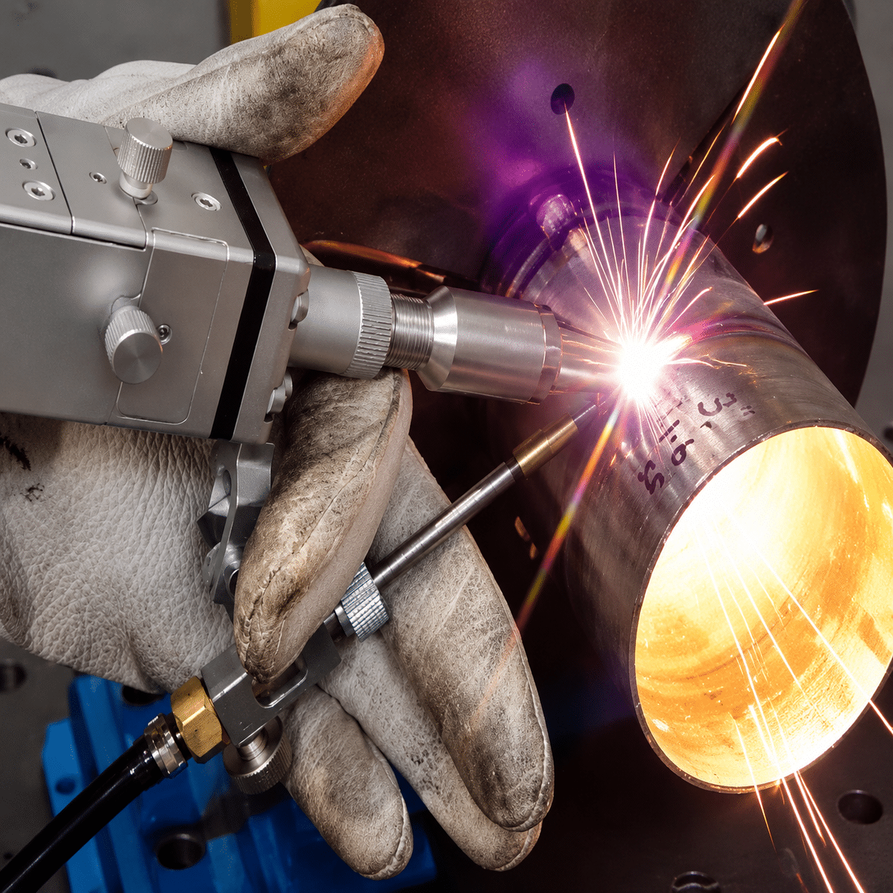
Wobble changes where and how often energy reaches the joint. Penetration, fusion area and gap tolerance must still be proven on the actual material stack.
The practical decision
Use wobble when a narrow static spot does not give enough seam width, positional tolerance or molten volume. Do not use it as permission to ignore joint preparation: gap width, mismatch, edge condition and filler volume still determine whether the joint has an acceptable load-bearing cross-section.
The laser traces a line, circle, ellipse, figure-eight or another supported path while moving along the seam.
It can enlarge weld width and reduce sensitivity to small offsets or gaps compared with a static focused spot.
At unchanged power and speed, excessive wobble can reduce peak power density and penetration.
Macrosections, strength tests and production variation—not surface appearance alone—must approve the process.
A focused spot with a second motion
In conventional laser seam welding, the focused spot follows the joint centerline. In wobble laser welding—also called beam oscillation welding—the optical system adds a rapid periodic motion around that forward path. The center of the pattern continues along the seam, but the spot repeatedly visits both sides of it. The resulting thermal footprint is usually wider than the optical spot itself.
Commercial systems produce this motion with scanner mirrors, an integrated wobble module or purpose-built handheld optics. IPG Photonics describes wobble welding as directing the focused beam over a wider area to broaden the seam and improve tolerance to process variables.[1] The concept is therefore best understood as spatial control of energy distribution, not as a simple power increase.
What happens inside the weld pool?
The moving heat source changes the temperature field, melt flow and keyhole behavior. Depending on the chosen path and timing, it may melt both joint edges more deliberately, enlarge the pool, circulate liquid metal and alter the depth-to-width ratio. Those changes can improve seam shape or help bubbles escape in a qualified window. They can also create lack of fusion, underfill or shallow penetration when the path is too wide or energy density becomes too low.
Four events define the process
- The optical spot is focused on or near the work surface.
- A scanner imposes a repeatable pattern with a specified width and frequency.
- The welding head or workpiece provides forward travel along the joint.
- The combined path determines local dwell, overlap, melting and solidification.
From narrow spot to designed thermal footprint
The laser source may be unchanged; the beam path changes the number, position and timing of interactions across the joint.
Define the centerline
Tooling, seam tracking or the operator keeps the pattern centered on the joint. Wobble adds tolerance, but it cannot rescue severe loss of joint alignment.
Choose the pattern
Line, circle, ellipse and figure-eight paths distribute energy differently across the center and edges. Pattern names and geometry vary by controller.
Set width and frequency
Width governs lateral reach; frequency governs how many pattern cycles occur during forward travel. Both change energy density and pool dynamics.
Balance heat and volume
Power, speed, focus, wire feed and shielding must provide sufficient molten metal and fusion without burn-through, underfill or excessive heat.
pitch = travel speed ÷ frequencyForward distance between consecutive pattern cycles, expressed in mm/cycle when speed is mm/s and frequency is Hz.
cycles/mm = frequency ÷ speedHow many complete wobble cycles occur per millimeter of seam. More cycles are not automatically better.
span ≈ path width + spot diameterA geometric estimate only. It does not predict fusion depth, strength, filler demand or the maximum acceptable joint gap.
The shape decides where energy returns
Controller libraries differ, and two patterns with the same nominal width can produce different dwell and edge heating. These diagrams show common path concepts, not universal recipes.
Line / transverse
Directly alternates between the two sides of the seam. Often useful when the goal is deliberate edge melting and a simple, wide path.
Watch edge dwellCircle
Continuously rotates the spot around the path center. It can broaden the pool and provide smooth redistribution, but direction and local dwell matter.
Check asymmetryEllipse
Adjusts the relationship between longitudinal and transverse movement. Useful when the weld needs different heating along and across the seam.
Confirm axis orientationFigure-eight / infinity
Crosses the centerline repeatedly and can redistribute energy toward both sides and the center. Research shows its effect depends strongly on the full parameter set.
Do not rank by name aloneSix controls that must move together
Changing only “wobble width” is not process development. Each setting alters the energy delivered per unit length, local peak intensity or molten-metal balance.
| Variable | What it changes | If pushed too far | What to verify |
|---|---|---|---|
| Laser power | Total optical energy available for melting and keyhole formation. | Too low can cause incomplete fusion; too high can cause burn-through, spatter or excessive penetration. | Cross-section, root condition and power stability. |
| Travel speed | Energy per unit seam length and the number of wobble cycles per millimeter. | Fast travel may underfill or miss fusion; slow travel may overheat, sag or enlarge the HAZ. | Linear energy, bead continuity and distortion. |
| Wobble width / amplitude | Lateral reach and the area over which power is distributed. | Excessive width can lower energy density and penetration even when the bead looks wide. | Confirm whether the controller reports radius, amplitude or total width. |
| Wobble frequency | Cycles per second, cycle pitch and how often the spot revisits each region. | Changing frequency can alter keyhole behavior, porosity and edge dwell; higher is not universally better. | Cycles/mm, process stability and high-speed observation when available. |
| Focus / spot size | Power density, depth-to-width ratio and tolerance to vertical position. | A small spot is demanding on alignment; an oversized spot may not reach required penetration. | Actual focal position, protective window condition and working distance. |
| Wire feed and shielding | Filler volume, alloy chemistry, underfill control and protection from oxidation. | Too little filler cannot replace missing joint volume; incorrect gas flow can create oxidation or turbulence. | Wire aim, feed synchronization, gas species, flow and nozzle position. |
Important: a displayed “2 mm wobble” may mean a 2 mm full width on one controller and a 2 mm radius or amplitude on another. Confirm the equipment definition before transferring parameters.
Wobble Coverage Planner
Translate speed, frequency and path width into geometry you can discuss with an applications engineer. This tool does not issue a weld procedure or approve a gap.
Enter the planned motion
Use total centerline path width—not radius—unless your machine documentation says otherwise.
Beam path spans the entered gap
The calculated swept span is wider than the gap, but this only describes optical coverage. It does not prove that enough molten metal exists to fill the joint.
Section the weld at the largest production gap. Verify both sidewalls are fused, the root is acceptable and the remaining load-bearing cross-section meets the drawing or applicable standard.
Wider coverage helps—missing metal still matters
A static laser spot can pass partly or completely through an open butt gap, or it can remain on one edge while the other edge receives too little energy. Wobble can direct the spot onto both edges, increase seam width and enlarge molten-pool volume. That is the basic reason it can improve tolerance to gap and seam-location variation.[1]
However, beam coverage and gap filling are not the same problem. A gap removes material from the joint. If the melted edges cannot supply enough volume, the result may be a concave bead, underfill, root dropout or reduced load-bearing area even when both edges are visibly melted. Filler wire, joint design, travel speed and clamping may be required.
Why no honest guide gives one universal maximum gap
Gap tolerance scales with sheet thickness, joint type, material, fit-up consistency, filler strategy, available power, beam size, pattern, focus and required acceptance level. TWI notes that conventional butt-joint laser welding commonly demands gaps below roughly 10% of material thickness, while improved clamping or advanced process variants can enlarge the window.[3] A published study using its specific optical setup found reliable results at a 0.2 mm gap and sufficient quality at 0.4 mm with beam oscillation; the same study also found strong sensitivity to pattern and speed.[2] Those results are evidence of potential—not a transferable machine specification.
Four production variables to measure
- Gap: record minimum, typical and maximum gap along a representative part set.
- Mismatch: one sheet edge may sit higher than the other even when the gap is small.
- Seam offset: quantify how far the beam center can drift from the true joint.
- Edge condition: burr, oxide, oil, coating and radius can change absorption and molten volume.
Static laser vs wobble laser welding
The better process is the one that meets the joint requirement with the widest stable production window—not the one with the more complex motion.
| Decision factor | Static beam | Wobble beam |
|---|---|---|
| Energy footprint | Narrow and concentrated around one moving spot. | Programmed across a wider path; local dwell depends on pattern and frequency. |
| Penetration potential | Often favors high power density and a narrow, deep keyhole at a given power and speed. | Can trade depth for width when energy is spread laterally; power or speed may need rebalancing. |
| Fit-up sensitivity | Usually requires precise joint position and small gaps. | Can increase tolerance to modest gap and offset variation when both edges are properly melted. |
| Bead appearance | Narrow bead; highly dependent on centering. | Can create a wider, smoother visual bead, but appearance does not confirm internal quality. |
| Programming | Fewer coupled variables and generally simpler parameter development. | Adds path, orientation, width and frequency to the welding procedure. |
| Best fit | Stable, accurately located joints where narrow heat input and penetration are priorities. | Applications needing seam-width control, more positional tolerance, controlled mixing or a tailored thermal footprint. |
Wobble can change defects—but it does not guarantee fewer defects
Beam oscillation changes the weld-pool flow and keyhole stability. The direction and size of that change depend on the chosen process window.
Potential improvements
When correctly developed, oscillation may broaden the pool, stabilize keyhole behavior, alter bubble escape paths, improve mixing and reduce sensitivity to seam placement. Research on particular aluminum and titanium setups has reported lower porosity at optimized frequencies and amplitudes.[4][5]
- More deliberate melting of both joint edges
- Wider process window for seam offset
- Possible porosity or spatter reduction in a tested window
- Tailored bead width and depth-to-width ratio
Possible new failure modes
The same motion can dilute power density, enlarge heat exposure or create non-uniform dwell. In one titanium study, a small tested amplitude produced more porosity than the conventional condition, while larger amplitude reduced penetration.[5]
- Shallow penetration or incomplete fusion
- Undercut or underfill from excessive gap volume
- Asymmetric fusion when the pattern is misoriented
- Instability when frequency, speed and wire feed are mismatched
What metals can be wobble welded?
The motion is broadly applicable, but it does not cancel each alloy’s reflectivity, thermal conductivity, vapor pressure, cracking tendency or shielding requirement.
Carbon and stainless steel
Wobble is often used to broaden lap, fillet and butt seams in sheet fabrication. Watch for loss of penetration when width increases, plus undercut or excessive heat tint when travel becomes too slow.
Verify root fusion and distortionAluminum alloys
Oscillation can influence keyhole stability, porosity and pool circulation. Oxide removal, alloy selection, shielding and cleanliness remain critical, and the optimum frequency is alloy- and geometry-specific.
Inspect pores and crackingCopper and conductive parts
A wider controlled path may help electrical joints, but near-infrared absorption, heat sinking and rapidly changing surface condition can make coupling unstable. Source wavelength and beam profile may matter more than wobble alone.
Measure resistance and pull strengthDissimilar metals
Beam motion can control how much of each side melts and mixes, but brittle intermetallic formation and galvanic behavior still govern whether a combination is practical.
Control dilution, not just widthCoated or galvanized steel
Wobble does not make zinc vapor disappear. Coating thickness, venting path, gap design, fume capture and process timing determine whether vapor can escape without porosity or expulsion.
Provide extraction and vapor pathThin and heat-sensitive parts
Wobble can spread energy, yet the larger heated footprint may not reduce total heat input. Balance power, speed and path size against burn-through, HAZ width and distortion.
Track linear energy and peak temperatureHandheld and automated wobble are not the same control problem
Both can use beam oscillation, but repeatability, seam tracking and parameter governance differ substantially.


Handheld system priorities
Ask whether the gun supports adjustable wobble width and frequency, how presets are locked, how contact tips set stand-off, how wire feed is synchronized and which safety interlocks stop emission when delivery integrity is lost.
- Operator motion is part of the procedure
- Consumable tip and protective window condition matter
- Workpiece contact and return-path logic must be understood
Automated system priorities
Ask how the robot, scanner and laser clocks are synchronized; how the pattern rotates around corners; how seam tracking changes the centerline; and how monitoring distinguishes a visual bead from acceptable internal fusion.
- Pattern orientation must follow joint coordinates
- Scanner calibration needs periodic verification
- Recipe control and traceability protect production
Qualify wobble welding in five controlled steps
The shortest route to a robust process is a designed test matrix that represents production variation—not random adjustment until one coupon looks good.
Define acceptance
Specify penetration, load-bearing area, strength, leak tightness, electrical resistance, appearance and allowable distortion.
Start from functionMap production variation
Measure material thickness, gap, mismatch, coating, edge condition, seam offset and fixture repeatability across real parts.
Test the extremesBuild a small matrix
Vary power, speed, width and frequency systematically. Keep focus, shielding and wire delivery controlled while observing the trade-offs.
One factor alone misleadsCut and test
Use macrosections, tensile or peel tests, leak tests, X-ray/CT where appropriate and electrical measurements for conductive joints.
Look below the beadLock the window
Define nominal settings plus allowed ranges, inspection frequency, calibration checks, change control and reaction plans.
Make it repeatableRead the defect as a process signal
Wide bead, shallow penetration
The path may be distributing energy too broadly for the available power and travel speed. Confirm focus and protective optics first, then compare a narrower path or revised energy balance. Do not solve the symptom by increasing power without checking burn-through at the minimum gap.
Underfill across larger gaps
The beam can reach both edges but there is not enough molten volume to replace the missing joint area. Reduce the root opening through tooling, add properly aimed filler wire, revise joint preparation or slow the process only after checking heat input and root stability.
One edge fuses; the other does not
Check seam center, pattern orientation, scanner calibration, torch angle and joint mismatch. Circular motion can also produce directional asymmetry when the travel direction, rotation direction and pool flow interact.
Porosity rises after adding wobble
Do not assume oscillation always releases gas. Verify surface cleaning, shielding, vapor path, keyhole behavior and the interaction of frequency with amplitude. Research shows porosity can first fall and then rise as oscillation parameters change.[5]
Spatter or unstable sound
Check whether the pattern repeatedly drives the beam through an open gap, whether power density is too high at a turnaround point, and whether wire is entering the correct part of the pool. Record high-speed video or photodiode signals when the application justifies monitoring.
Applications that benefit from controlled seam width
Wobble is most valuable where part variation, seam appearance, mixing or a deliberately wide fusion zone matters enough to justify the additional process variables.
Sheet-metal fabrication
Cabinets, doors, kitchenware and enclosures often use lap, corner and fillet joints where a wider visual bead and modest fit-up tolerance are valuable.
Watch cosmetic quality and distortionTubes and profiles
Round and rectangular products need stable orientation around changing geometry. Automation can coordinate the pattern with rotation and seam tracking.
Verify start/stop and cornersBattery and electrical joints
Beam motion can tailor overlap and mixing for tabs, busbars and terminals. Joint resistance, intermetallics, porosity and spatter are more important than bead width alone.
Measure electrical performanceAutomotive assemblies
High-volume parts may use wobble to enlarge the process window for component position, but validated fixtures and monitoring are still needed to protect yield.
Design for cycle-time consistencyPrecision components
Medical, electronic and sensor housings may benefit from programmed energy placement, provided the larger footprint does not exceed the thermal budget.
Control contamination and HAZDissimilar combinations
A pattern can bias energy toward one side or mix the pool more deliberately. Metallurgical compatibility must still be confirmed through sectioning and testing.
Treat dilution as a design variableSurface beauty is only one acceptance criterion
A wobble path can produce a wide, regular bead. Internal fusion and effective cross-section still decide whether the joint carries load, seals or conducts current.


Wobble changes the beam path—not the hazard class
Industrial fiber welders are commonly Class 4 laser systems. Direct, reflected and diffusely scattered radiation can injure eyes and skin; the process can also create fire, electrical and fume hazards.
Engineering controls first
Use a validated enclosure or controlled laser area, interlocks, emission warning, beam containment, protected delivery fiber, safe workholding and source-capture fume extraction. OSHA identifies Class 4 systems as hazardous for direct and diffuse viewing and as potential skin and fire hazards.[6]
- Complete a site-specific laser risk assessment
- Control specular reflections from metal surfaces
- Use extraction appropriate to alloy and coatings
PPE does not replace containment
Laser eyewear must match the wavelength and required optical density; welding PPE must also address hot metal, plume and conventional mechanical hazards. Training, authorization and a laser safety officer’s program are required where applicable.
- Never rely on ordinary welding shade for fiber-laser protection
- Inspect protective windows, interlocks and enclosures
- Follow local regulations and the equipment manufacturer’s instructions
Questions to ask before buying a wobble laser welder
Compare systems by measurable capability and application evidence, not only by advertised power or maximum wobble width.
What exactly is adjustable?
Ask for supported patterns, maximum width at working distance, frequency range, orientation control and whether values mean radius or total width.
Request the controller manualHow is the process validated?
Request weld samples in your alloy, thickness, joint type and maximum gap. Ask for macrosections and relevant mechanical, leak or electrical tests.
Demand evidence below the surfaceHow are recipes controlled?
Confirm password levels, parameter limits, job storage, traceability, calibration and whether an operator can change critical settings during production.
Protect the qualified windowIs filler wire integrated?
For variable or open gaps, ask how wire angle, feed speed and start/stop timing are synchronized with the beam and travel motion.
Match filler volume to the gapWhat safety architecture is included?
Review interlocks, enclosure concept, contact monitoring, emergency stops, fume extraction and the documentation required for your jurisdiction.
Price the complete safe cellWhat support follows delivery?
Ask who develops the initial procedure, trains operators, supplies optics and tips, diagnoses unstable welds and supports future materials.
Buy application support, not wattsMove from concept to a tested process
Use these pages to compare machine architecture, material behavior and production requirements before requesting a sample weld.
Handheld Laser Welding Machine
Review the main system components, cooling, wire feed and application fit.
Explore the machine → ApplicationSheet Metal Laser Welding
Understand joint design, material thickness and production factors for fabricated sheet parts.
Read the application → Material guideAluminum Laser Welding
Review oxide, porosity, alloy and shielding issues before transferring a recipe.
Study aluminum welding → Application reviewValidate a Sample Joint
Share the material, thickness, joint drawing, gap range and acceptance target for a focused review.
Start the discussion →Wobble laser welding questions
Concise answers to the questions buyers and process engineers ask most often.
What is wobble laser welding?
Wobble laser welding is a laser welding method in which the focused spot follows a programmed oscillating pattern while the head or workpiece travels along the joint. The motion distributes energy over a wider area than a static spot and can change seam width, melt flow and tolerance to fit-up variation.
Does wobble welding fill any size gap?
No. It can improve gap tolerance by melting both joint edges and increasing molten-pool width, but the allowable gap depends on sheet thickness, material, joint design, filler volume, pattern, power, speed and acceptance criteria. A supplier’s maximum value is not transferable without testing your joint.
Is wobble laser welding stronger than conventional laser welding?
Not automatically. Strength depends on fusion area, penetration, porosity, underfill, microstructure and base-material behavior. Wobble can improve those outcomes in a qualified window, or reduce strength if energy is spread so widely that fusion becomes shallow.
Which wobble pattern is best?
There is no universal winner. Line, circle, ellipse and figure-eight patterns produce different dwell and melt-flow behavior. The preferred pattern changes with joint geometry, travel direction, material, gap and required penetration. Compare patterns with controlled trials and cross-sections.
What is the difference between wobble width and weld width?
Wobble width describes the programmed lateral motion of the beam center. Weld width is the resulting fused or visibly melted width. The latter also depends on spot size, power, speed, focus, conductivity and material response, so the two values are not equal.
Does higher wobble frequency improve weld quality?
Not by itself. Higher frequency increases cycles per unit length at a fixed travel speed, but it also changes local dwell, keyhole behavior and pool circulation. Published results show optimized frequency windows rather than a simple “higher is better” rule.
Can handheld laser welders use wobble?
Yes. Many handheld systems integrate one- or two-axis beam motion and stored presets. The operator’s travel speed, angle, stand-off and seam following remain part of the process, so procedure control and training are still required.
When is filler wire needed?
Filler becomes important when a gap removes more material than the melted edges can replace, when underfill must be controlled, or when alloy chemistry needs modification. Wire aim and feed rate must be developed with the wobble pattern and travel speed.
How should a wobble weld be inspected?
Begin with visual inspection, then use macrosections to confirm sidewall fusion, penetration and remaining cross-section. Add tensile, bend, peel, leak, fatigue, X-ray/CT or electrical-resistance tests according to the joint function and applicable standard.
Evidence used in this guide
Manufacturer information establishes commercial capability; peer-reviewed research and independent technical guidance define the limits and application-specific nature of the process.
- IPG Photonics — Wobble Welding Heads. Commercial description of adjustable beam patterns, wider seams and increased tolerance to process variables.
- Müller et al. — Effects of Reduced Ambient Pressure and Beam Oscillation on Gap Bridging Ability during Solid-State Laser Beam Welding, Journal of Manufacturing and Materials Processing, 2020.
- TWI — How can I increase the tolerance of laser welding to joint fit-up? Independent overview of fit-up requirements and control options.
- Dittrich et al. — Process Stability during Laser Beam Welding with Beam Oscillation and Wire Feed, Journal of Manufacturing and Materials Processing, 2019.
- Weld formation and porosity in TC4 joint by oscillating laser beam welding with circle trajectory model, Journal of Materials Research and Technology, 2024.
- OSHA Technical Manual, Section III, Chapter 6 — Laser Hazards. Classification and control principles for high-power laser systems.
Find the wobble window for your actual joint.
Send the alloy, thickness, joint type, measured gap range, production volume and acceptance target. Oceanplayer can use those details to recommend a machine direction and a focused sample-test plan.