


6 Types of Laser Welding Processes Explained
Conduction, keyhole, hybrid laser-arc, remote/scanner, spot and oscillation welding are six useful ways to describe industrial laser welding. They do not all sit at the same classification level, so this guide explains what each term really means, where it works and what must be validated before equipment selection.
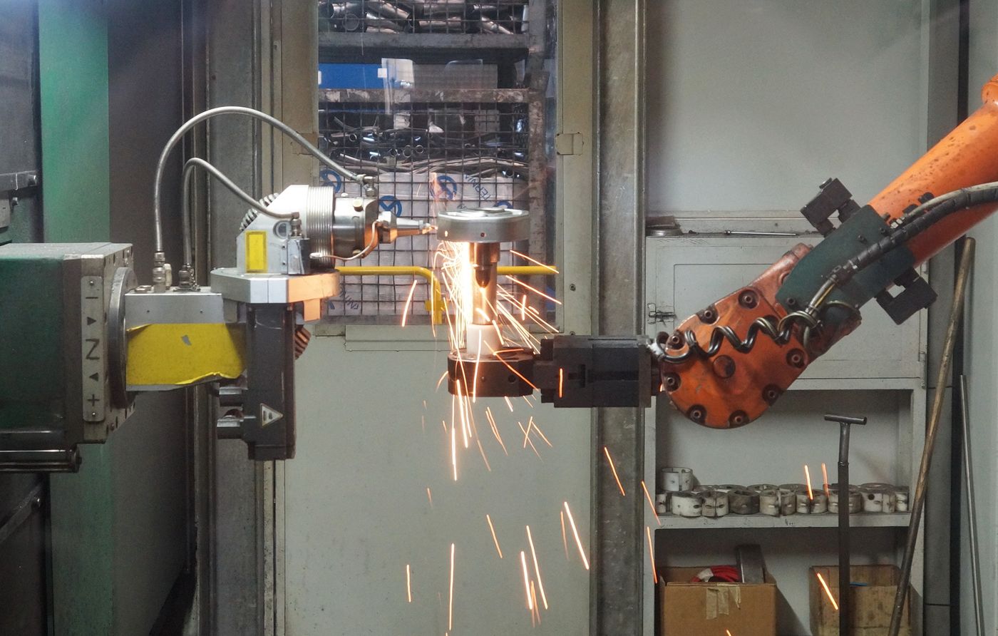
Image: TRUMPF GmbH + Co. KG / Wikimedia Commons, CC BY-SA 3.0.What are the six types of laser welding?
The two fundamental metal–beam interaction modes are conduction welding and keyhole welding. Four widely used production variants are hybrid laser-arc welding, remote or scanner welding, laser spot welding and oscillation or wobble welding.
That distinction matters. Conduction and keyhole describe how energy creates the weld pool. Hybrid describes a second heat source added to the pool. Remote and wobble describe how optics move the beam. Spot describes the weld geometry and exposure strategy. A production system may therefore combine several labels—for example, remote keyhole welding with beam oscillation.
From physics to production
Use the overview for a fast comparison, then open the process that matches your joint challenge.
One weld can belong to several “types.”
Do not treat the six names as six mutually exclusive machine settings. Start with the physical regime, then define the energy source, beam-delivery method and weld format. This produces a usable process specification instead of a marketing label.
Defines whether energy remains surface-led or creates a vapor cavity for deep penetration.
Adds an arc and usually filler wire to the same process zone.
Scanner optics reposition or oscillate the focused spot.
Defines whether the joint is made by discrete welds or a traversing seam.
Six laser welding processes at a glance
The table compares practical tendencies, not guaranteed limits. Material grade, absorptivity, focal spot, beam quality, joint design and actual power at the workpiece can move every boundary.
| Process | Primary purpose | Typical weld character | Fit-up tolerance | Best production context | Main validation risk |
|---|---|---|---|---|---|
| Conduction | Controlled surface melting | Wide, shallow, smooth bead | Low to moderate | Thin sheet, visible seams, hermetic covers | Incomplete fusion or accidental transition to keyhole |
| Keyhole | Deep penetration with concentrated heat | Narrow seam with high depth-to-width ratio | Usually low without filler | Structural seams, gears, tubes and thicker sections | Keyhole instability, porosity and root consistency |
| Hybrid laser-arc | Combine penetration with filler and gap bridging | Deep fusion with a broader, filled crown | Higher than autogenous laser welding | Thicker plate, long seams, structural fabrication | Coupling laser, arc, wire and shielding parameters |
| Remote/scanner | Minimize positioning time across many welds | Short seams, stitches or spots across a scan field | Depends on underlying regime | High-volume automotive and battery assemblies | Focus, seam location, fixture and plume control |
| Spot | Create a discrete micro or precision joint | Single nugget or overlapping pulse train | Very sensitive on stacked foils | Electronics, medical, battery tabs and jewelry | Contact gap, pulse shape and part-to-part reflectivity |
| Oscillation/wobble | Broaden the seam and enlarge the process window | Programmable circular, linear or figure-eight path | Often better than a static small spot | Handheld welding, batteries and difficult fit-up | Too much width, insufficient penetration or excess heat |
Engineering note: “best” means a useful starting point for trials. It does not replace procedure qualification, metallography, mechanical testing or application-specific acceptance criteria.
Conduction and keyhole are the two fundamental regimes.
TWI describes conduction-limited and keyhole welding as the two basic operating modes. Power density at the workpiece—not the rated laser power by itself—governs the transition.
Conduction regime
The surface absorbs the beam and heat conducts into the material. The pool remains relatively broad and shallow because metal vaporization is limited.
Keyhole regime
Localized vaporization creates a cavity that lets energy couple through the thickness. Molten metal flows around the moving cavity and solidifies behind it.
How each laser welding process works
Each chapter answers four buyer questions: what changes physically, which joint problem it solves, what equipment it adds and what can go wrong.
Conduction laser welding
Conduction welding keeps the process below sustained keyhole formation. Heat enters at the irradiated surface and spreads through the workpiece, producing a weld that is generally wider than it is deep. TWI gives a typical conduction-limited power density below about 105 W/cm², but the actual transition depends on the material, beam distribution and travel conditions.
Choose this regime when bead appearance, low spatter and controlled penetration matter more than maximum depth. It is useful for thin stainless enclosures, precision covers, medical-device housings, edge seams and parts where a narrow deep keyhole would create burn-through risk. It can be produced with continuous-wave or pulsed sources; “conduction” describes the interaction, not a specific laser architecture.
Lap, edge and small butt seams are common starting geometries.
These determine whether the pool remains shallow or crosses into keyhole behavior.
A process operating near the transition can alternate between shallow and deep penetration.
Do not approve a cosmetic bead from the top surface alone. Section the joint at starts, steady-state locations, corners and stops to confirm fusion at the interface.
Keyhole or deep-penetration welding
When the focused beam produces sufficiently high power density, material melts and vaporizes before conduction can remove the energy. Vapor pressure holds open a narrow cavity. The beam couples into this cavity, so penetration can become much deeper relative to seam width than in conduction welding.
Keyhole welding is the principal route for narrow structural seams, full-penetration tube and plate joints, powertrain parts and applications where fewer passes and limited distortion are important. It rewards tight fit-up and accurate seam tracking. The same concentrated interaction that creates deep penetration can also produce pores, spatter, undercut and root inconsistency when the cavity fluctuates or collapses.
Butt, overlap, stake and some T-joints can benefit when access and focus are stable.
Actual power at the workpiece and optical cleanliness matter as much as nominal wattage.
These often signal an unstable keyhole, incorrect focus or unfavorable joint conditions.
Record cross-sections, penetration statistics and internal inspection—not only the best coupon. A narrow seam can hide incomplete penetration or trapped pores below an attractive crown.
Hybrid laser-arc welding
Hybrid laser-arc welding couples a laser and an arc process—commonly GMAW/MIG/MAG—into the same process zone or weld pool. The laser supplies concentrated penetration while the arc contributes additional heat and filler metal. This pairing can widen the usable fit-up window and tailor weld chemistry or reinforcement.
The process is attractive for thicker structural material, long plate seams, shipbuilding panels, pipelines and assemblies where autogenous laser welding would demand unrealistic gap control. It is not simply “laser plus MIG run nearby.” The laser-to-arc distance, leading/trailing arrangement, wire feed, arc parameters, focus, speed and shielding must form one coupled process.
It can reduce pass count while retaining metallurgical adjustment through wire selection.
Two individually stable processes may still be unstable when coupled incorrectly.
Joint preparation and coordinated parameter control remain essential.
Hybrid welding adds an arc source, wire system, torch, consumables and integration complexity. Evaluate it against total seam cost, distortion correction and pass count—not laser speed alone.
Remote or scanner laser welding
Remote welding uses rapidly moving mirrors to direct the beam across a working field. The optical system can jump between weld positions far faster than a robot can reposition a conventional head. TRUMPF describes scanner welding as a way to reduce non-productive movement while programming spots, stitches and contours over a defined field.
This is a delivery architecture, not a separate melt mechanism: each programmed seam may still run in conduction or keyhole mode, and the scanner can add oscillation. Remote welding is most valuable when a part contains many short welds and positioning time would otherwise dominate cycle time—for example body-in-white components, seat structures, battery assemblies and sheet-metal subassemblies.
High utilization and short repositioning time justify the optical complexity.
Fixture variation must be measured or controlled across the complete field.
Vision, calibration and process monitoring are often central to production stability.
Laser spot welding
Laser spot welding creates a discrete weld nugget rather than a continuous traversing seam. Energy may be delivered as a shaped millisecond pulse, a burst, or a controlled continuous-wave dwell. The process format is especially useful where heat must be localized or where many small electrical and mechanical connections are required.
Typical applications include battery tabs, sensor lids, fine wires, electronic packages, medical components and jewelry repair. Thin stacked materials are highly sensitive to contact gap: the upper foil can melt without transferring enough energy across the interface. Clamping, surface condition and pulse shape therefore become part of the welding process—not merely fixture details.
The process localizes heat and can protect nearby temperature-sensitive features.
Ramp profiles can change absorption, peak temperature and solidification behavior.
Electrical resistance or pull testing may reveal defects invisible from the top.
Define nugget diameter, interface width, indentation or crown limits and electrical performance separately. A bright circular mark does not prove a functional interfacial weld.
Oscillation or wobble laser welding
Wobble welding moves the focused spot in a programmed pattern—such as a circle, line or figure eight—while the head or part travels along the joint. IPG notes that directing the beam over a wider area broadens the seam and increases tolerance to process variables such as unexpected gaps.
The technique is common in handheld laser welders, battery joining, busbar welding and automated cells that need a wider seam than a static spot provides. Oscillation modifies melt-pool flow and heat distribution, but it does not eliminate the need for adequate penetration. A pattern that creates an attractive wide crown can still leave an unfused root.
It can enlarge the usable process window without increasing the natural spot diameter.
These variables interact with power, focus, material and joint orientation.
More motion is not automatically more stable; validate penetration throughout the pattern.
Change one pattern variable at a time and record cross-sections. Comparing only top-bead width makes it easy to select a visually smooth but mechanically weak setting.
Which laser welding process should you evaluate first?
Choose the closest production conditions. The result is a trial route, not a qualified welding procedure.
Describe the joint
Use the engineering constraint that is hardest to change—not the machine already available.
Start with keyhole welding
A controlled keyhole trial is the direct starting route for a deep seam in well-fitted thin sheet. Validate focus, root consistency and porosity before choosing power.
Choose the process before choosing the laser power.
Rated watts do not define a production solution. Work backward from the joint and acceptance criteria to the beam source, optics, motion system, fixture and monitoring package.
Start with geometry and access
Define lap, butt, fillet, edge or stake geometry, one-sided access, seam orientation and required root condition.
- Joint gap and mismatch distribution
- Focus access and collision envelope
- Start, stop and corner requirements
Map the material stack
Grade, thickness, coating, reflectivity, conductivity and dissimilar combinations shape the usable process window.
- Actual production surface condition
- Coatings or plated layers
- Cracking and intermetallic risks
Define measurable acceptance
Translate “good weld” into penetration, interface width, porosity, strength, leak rate, resistance and appearance limits.
- Cross-section sampling plan
- Mechanical or electrical test
- Non-destructive inspection method
Measure variation, not nominal CAD
A small-spot autogenous process may fail when real stamped, formed or assembled parts move beyond drawing nominal.
- Gap capability study
- Fixture and clamp repeatability
- Seam tracking requirement
Separate welding from motion
For many short seams, scanner utilization may matter more than raw travel speed. For a long seam, stable continuous operation dominates.
- Weld-on time per part
- Repositioning and loading time
- Parallel stations and changeover
Specify the complete process cell
The source is only one element. Optics, chiller, extraction, shielding, wire, robot, safety enclosure and sensors determine readiness.
- Power at the workpiece
- Protective glass monitoring
- Service and spare strategy
Use the process to widen the window—not to hide the defect.
Changing the laser welding type can address a dominant failure mechanism, but it cannot compensate for contaminated material, poor clamping or an undefined acceptance standard.
Stabilize the cavity and gas path
Keyhole collapse, coatings, moisture and gas entrapment can create internal pores. Compare focus, speed, shielding, beam shaping and oscillation while controlling surface condition.
Broaden the interaction or add filler
Oscillation can widen a seam for small variation. Larger or metallurgically important gaps may require hybrid laser-arc welding or controlled wire-fed laser welding.
Reduce peak interaction and improve heat sinking
Conduction mode, a larger spot, higher travel speed, pulse shaping or better backing can protect thin material. Confirm that the interface still reaches fusion.
Verify energy reaches the interface
A wider wobble pattern or attractive spot does not guarantee root fusion. Check focus, overlap, contact gap, seam location and actual delivered power.
Control recoil pressure and pool motion
Spatter may indicate excessive intensity, unstable keyhole behavior or a poorly selected oscillation pattern. Inspect optics because contamination can become a second failure.
Treat metallurgy and restraint together
Material chemistry, filler selection, cooling rate, joint design and restraint affect cracking. Hybrid or wire-fed processes may help, but require procedure-level validation.
A six-step validation path for laser welding
A vendor demonstration proves that a coupon can be joined. Production qualification proves the process remains acceptable across material, part and equipment variation.
Freeze the joint definition
Collect drawings, material certificates, coatings, thickness tolerances, gap data, cleanliness and acceptance requirements.
Compare two credible routes
Use small test matrices to compare interaction mode, beam motion, filler need and wavelength instead of optimizing one assumption.
Find the operating window
Vary power, speed, focus, shielding and pattern to identify a stable region rather than one best-looking setpoint.
Inspect inside the weld
Use macrosections, mechanical tests, leak/electrical tests and suitable NDT against written acceptance criteria.
Challenge real production limits
Test worst-case gap, coating, alignment, thermal state, start/stop conditions and multiple material lots.
Lock monitoring and maintenance
Define recipes, access control, calibration, protective-glass limits, sensor alarms, sampling and reaction plans.
Give the application engineer production evidence.
The fastest useful trial begins with the actual material and joint. Lab-grade flat coupons cannot expose every coating, gap and fixture problem present on the real part.
Industrial laser welding requires engineered controls.
High-power welding systems are commonly Class 4 at the source or during service. The enclosure may make normal production operation accessible as Class 1, but commissioning, maintenance and open-beam work require a documented hazard assessment.
Plan controls around the real beam and material
OSHA guidance identifies direct, specular and some diffuse viewing hazards for Class 4 lasers, together with potential skin, fire and laser-generated airborne contaminant hazards. A complete installation may need a certified enclosure, interlocked access, warning systems, beam termination, wavelength-rated eyewear for authorized tasks, fume extraction, training, written procedures and a laser safety officer or equivalent competent oversight.
Remote and wobble optics make the hazard envelope dynamic. Reflective copper, aluminum and polished stainless surfaces deserve particular attention during setup because an unexpected beam path can differ from the programmed weld path.
Do not choose a process solely because it makes the weld. Choose the process that can make, verify and contain the weld under production conditions.
Related laser welding tools and guides
Questions about laser welding process types
What are the two fundamental modes of laser welding?
Are remote and wobble welding separate from keyhole welding?
Which laser welding process gives the deepest penetration?
Which process is best for thin stainless steel?
Which process handles a joint gap best?
Is laser spot welding always pulsed?
When does remote scanner welding make financial sense?
Does wobble welding always reduce porosity?
Does hybrid laser-arc welding always use filler wire?
How should a laser welding process be qualified?
Validate the process on your real material and joint.
Share the material stack, thickness, joint drawing, gap range and acceptance criteria. Oceanplayer can help identify two credible process routes and plan sample welds before a machine configuration is finalized.