

What Are the Typical Speeds for Laser Welding?
Laser welding travel speed can range from well below 1 m/min in demanding deep or manually guided work to 10 m/min and beyond in highly controlled thin-section or high-brightness applications. There is no single "normal" speed: material, thickness, power density, joint geometry, beam motion, filler, fit-up and the required cross-section set the usable window.

Nominal line energy is only the beginning. Spot size, focus, absorption, beam profile and joint conditions determine what the material actually experiences.
Image: Krorc / Wikimedia Commons, CC BY-SA 3.0.
The practical speed verdict
Start with a material- and joint-specific evidence range. Then qualify the fastest speed that still meets penetration, fusion, geometry, appearance and mechanical or leak requirements at real production tolerances.
A center value hides sensitivity. Develop lower, nominal and upper speed limits while holding the other recorded variables under control.
At fixed laser power, increasing forward travel speed reduces nominal energy delivered per millimeter of seam.
A higher travel rate can lower accepted output when it creates underfill, lack of fusion, spatter, porosity or extra inspection and rework.
A clean top bead cannot prove penetration or interface width. Verify the feature that makes the joint functional.
What speed ranges appear in real laser-welding evidence?
The most useful way to answer "what is a typical laser welding speed?" is to compare documented applications with all their surrounding conditions. A speed becomes meaningful only when it is tied to material grade, thickness or target depth, joint type, laser power, spot or beam profile, focus and acceptance result.
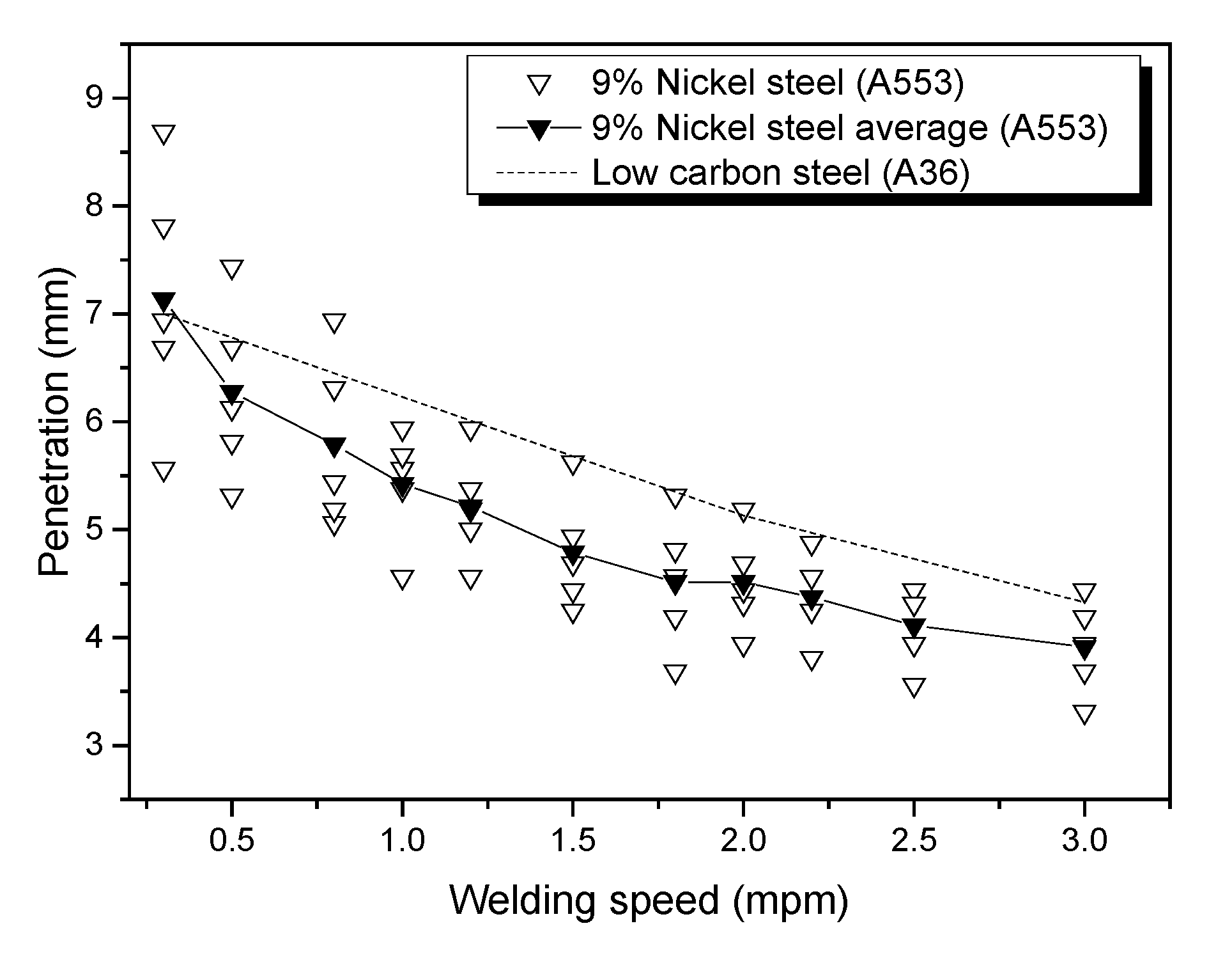
For example, a peer-reviewed bead-on-plate study of 15 mm ASTM A553-1 steel deliberately tested speeds from 0.3 to 3.0 m/min at 3-5 kW. That is an experimental matrix, not a claim that every point produced an acceptable joint. By contrast, a Coherent application note reports 12 m/min at 1 mm weld depth in copper using a 4 kW adjustable-ring-mode laser. Both numbers are valid in their own context; neither is a generic setting for another machine.
A useful screening interpretation
For early planning, speeds below 1 m/min often signal deeper sections, lower available power density, filler deposition, difficult geometry or manual control. The 1-5 m/min region appears frequently in industrial development work. Speeds from 5-12 m/min occur in well-controlled thin sheet, powertrain, remote and copper applications with suitable beam delivery. Much higher values are possible in specialized foil and scanner processes, but those applications should not define expectations for handheld sheet-metal welding.
| Published application | Material / geometry | Laser condition | Reported speed | How to interpret it |
|---|---|---|---|---|
| 9% nickel steel experiment | 15 mm ASTM A553-1 bead-on-plate coupons | 3-5 kW fiber laser; fixed focus; nitrogen shielding | 0.3-3.0 m/min test matrix | Shows how penetration and bead geometry changed across a controlled research matrix; not every test point was defect-free. |
| AISI 304 research examples | 4 and 6 mm stainless bead-on-plate specimens | 1-3 kW disk laser; 200 um spot; fixed shielding setup | 0.5-2.0 m/min examples | Demonstrates that power and speed combinations - not thickness alone - produced partial or full penetration. |
| Aluminum body-in-white | 0.8 mm 5xxx-to-6xxx aluminum overlap application | Adjustable ring/core fiber beam; no filler | 5 m/min | An application-lab result for a specific beam distribution and alloy combination. |
| Low-carbon steel powertrain | High-precision gear / powertrain component trial | 2 kW total ring/core power with argon | 5 m/min | A throughput-driven result using a beam profile selected to control spatter and HAZ. |
| Copper e-mobility trial | Copper with 1 mm reported weld depth | 4 kW high-brightness adjustable ring mode | 12 m/min | Shows what a specialized beam and copper-specific setup achieved; it is not a general handheld speed. |
Published values are reproduced as application examples from the technical sources listed near the end of this page. They are not Oceanplayer parameter recommendations or thickness guarantees.
Slow relative travel
Often associated with deeper energy demand, manual travel, difficult access, wire deposition or limited available power density. Excess thermal exposure must still be checked.
Common development region
Frequently encountered in industrial sheet, plate and component studies. The acceptable point varies widely with power, beam and joint.
High-throughput region
Possible in thin, precise or specialized applications with stable positioning, suitable beam delivery and adequate power density.
Specialized process territory
Remote, scanner, foil or advanced beam-shaping processes may go higher. Motion capability alone does not prove weld quality.
Convert travel speed into line energy and cycle time.
This calculator performs unit conversion and steady-power planning math. It does not predict penetration, strength, allowable thickness or a qualified welding procedure.
Enter the planning values
Use forward seam travel speed - not wobble frequency, internal scanner velocity or rapid repositioning speed.
Nominal laser output energy per millimeter before absorption or process-efficiency assumptions.
At fixed power, faster travel usually reduces weld dimensions.
The simplest comparison is nominal line energy:
If a 2 kW laser travels at 50 mm/s, the gross value is 40 J/mm. Double the speed to 100 mm/s without changing power and it falls to 20 J/mm. This does not mean two processes with 40 J/mm will produce the same weld: absorption, wavelength, focus, spot size, beam profile, wobble path, keyhole behavior and joint geometry redistribute that energy.
In the ASTM A553-1 study shown here, increasing speed reduced penetration depth and affected bead geometry under the tested conditions. That direction is common at fixed setup, but a different beam or power level can move the entire process window.
Absorption and heat flow
Reflectivity at the laser wavelength, thermal conductivity, melting behavior, coatings and alloy chemistry affect how much of the incident energy becomes a stable weld.
- Copper can demand specialized wavelength or beam control
- Aluminum needs crack and porosity control
- Steel grades respond differently to cooling rate
Required fusion volume
More depth or cross-sectional area generally requires more delivered energy, but thickness alone cannot select speed because joint design and power density may change the target.
- Full vs partial penetration
- Single vs multiple pass
- Root width and throat requirement
Spot, focus and profile
A high-brightness center, ring beam, defocused spot or wobble path creates a different intensity distribution. "Same power" does not mean "same welding capability."
- Focus position
- Core/ring ratio
- Wobble width and frequency
Fit-up and seam access
Butt, lap, edge and fillet joints place the beam and fusion requirement differently. Gap, mismatch and seam-position variation can lower the usable speed.
- Edge contact and gap
- Beam aim tolerance
- Fixture repeatability
Wire adds a synchronized flow
Wire-assisted welding must melt, position and incorporate the filler while maintaining edge fusion. Travel speed and wire feed rate must be developed together.
- Wire alloy and diameter
- Feed-to-travel ratio
- Guide angle and start timing
The part defines "fast enough"
An appearance seam, hermetic enclosure, structural joint and electrical connection do not share the same acceptance gate or optimal speed.
- Section and penetration
- Strength or fatigue
- Leak, resistance or appearance

Why a thickness-only speed table can mislead buyers.
A 2 mm butt joint seeking full penetration is not equivalent to a 2 mm lap joint needing a controlled interface width. A fillet may require added throat and wire. A visible edge seam may prioritize a smooth cap and minimal distortion. These different targets can use different speeds on the same base material.
Heat-conduction welding produces a relatively shallow, wider melt zone without a sustained keyhole. Deep-penetration welding uses a vapor capillary and can create a narrow, high-aspect-ratio seam. A change in speed can move stability, dimensions or even the operating mode, so the speed must be assessed together with power density and focus.
Joint-specific questions
- Must the weld penetrate completely or only reach an interface?
- What is the minimum acceptable root or interface width?
- How much gap, mismatch and seam-position error occurs in production?
- Is filler required for volume or metallurgy?
- Are corners, starts and stops included in the cycle target?
Too fast and too slow can both destabilize quality.
Travel speed is rarely the only cause. Use the symptoms to investigate the complete parameter set rather than changing speed in isolation.
Insufficient or unstable energy delivery
The beam moves before the required fusion geometry can form, or the melt/keyhole cannot remain stable at the chosen power and beam distribution.
- Insufficient penetration or interface width
- Intermittent lack of fusion
- Narrow bead and underfill
- Humping or unstable surface profile
- Poor filler incorporation
- Failed leak, strength or resistance result
Excessive local thermal exposure
The joint receives more nominal energy per millimeter and the molten pool may become too large or remain hot longer than the product tolerates.
- Excessive width or penetration
- Burn-through or root sag
- Distortion and enlarged thermal footprint
- More vaporization, spatter or porosity in some materials
- Excessive intermetallic growth in dissimilar joints
- Unwanted heat tint or surface damage
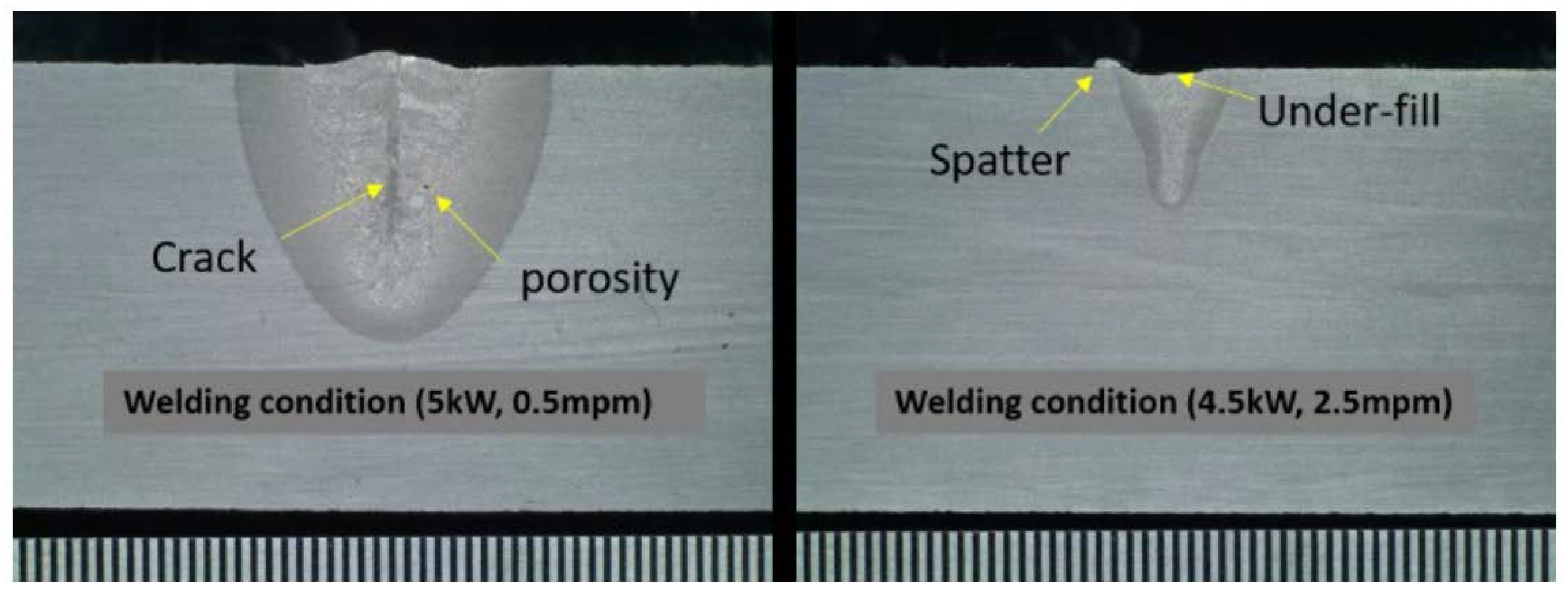
Section and test the failure mode.
This research figure documents multiple defects in one defined material and parameter study. The lesson is not that one speed always causes one defect; it is that the process window must be connected to actual evidence.
Kim et al., Metals 2020, CC BY 4.0 ->The machine architecture changes the usable speed.
Handheld laser welding depends on operator posture, vision, seam access, gun angle and the ability to maintain consistent forward travel. The machine may be capable of a higher process rate than an operator can safely and repeatedly hold around a real assembly. For this reason, straight test coupons can overstate production speed.
Robot or cobot welding can repeat a programmed path and coordinate starts, stops, corners and wire feed. The gain is not simply faster travel. Repeatability makes it possible to operate closer to the verified upper speed boundary while documenting the same motion from part to part.
Remote scanner welding moves the beam rapidly with mirrors across a work field. It can reduce dead time between seams and support high process speeds, especially on thin and highly repeatable parts. Yet scanner repositioning speed and qualified welding speed remain different values.
Fiber laser does not automatically mean "fastest"
Modern fiber-delivered solid-state lasers are efficient, compact and well suited to automation, but welding speed comes from the complete optical and material interaction. Wavelength, brightness, spot size, beam shape, material absorption and process stability can matter more than the generic source label. A green, blue, ring-mode or single-mode source may outperform a standard infrared multimode beam in a specific copper task, while another joint may favor a different architecture.
Accepted parts per hour is the real productivity metric.
A 600 mm seam welded at 3 m/min needs 12 seconds of beam-on time. Two seams need 24 seconds. If loading, clamping, repositioning and unloading add 30 seconds, the ideal part cycle is already 54 seconds before inspection, maintenance and availability losses. The calculator above makes this distinction visible.
Increasing travel speed from 3 to 4 m/min saves only six seconds of beam-on time for two 600 mm seams. If the change raises reject or rework rate, the higher speed can reduce output. Conversely, better fixturing, seam tracking or handling can improve output without touching the welding parameter.
Measure three speed layers
- Travel speed: forward beam movement during the weld.
- Cycle speed: completed parts per hour including handling and repositioning.
- Accepted output: conforming parts per shift after inspection, scrap and rework.

Build a speed window in eight controlled steps.
The objective is not the prettiest single coupon. It is a repeatable lower-to-upper operating window that survives real variation and meets the product's acceptance criteria.
Define the joint
Record material grades, thicknesses, coating, joint drawing, weld length, gap and fixture condition.
Define acceptance
Set penetration, interface width, throat, appearance, distortion, strength, leak or resistance targets first.
Lock the optics
Document wavelength, beam profile, spot size, focus, angle and wobble or scanner path.
Choose a safe center
Use comparable evidence or application-lab experience to choose a conservative initial power-speed pair.
Change one variable
Bracket speed while holding the other recorded conditions constant; do not tune everything simultaneously.
Inspect internally
Section starts, steady travel, corners and stops. Add the required mechanical, electrical, NDT or leak test.
Challenge tolerance
Repeat at minimum and maximum gap, part lots, orientations, operators and production temperatures.
Release with limits
Document nominal speed, allowable range, alarms, inspection frequency and response to drift.
High speed may control distortion and discoloration, but seam tracking and fit-up determine whether fusion remains continuous.
Speed must be developed with beam distribution, alloy pairing, crack sensitivity, surface condition and porosity control.
High conductivity and wavelength-dependent absorption make source brightness, beam shape and stability central to the speed result.
Travel speed must coordinate with wire volume, position, melting and the required fillet throat - not only penetration.
Cycle targets, spatter, particles, HAZ and repeatable penetration can drive beam-shaping and monitoring decisions.
Leak integrity, starts and stops may matter more than nominal straight-line speed; qualify the entire closed path.
Turn a target cycle into a qualified weld trial.
Send the material, thickness, joint drawing, gap range, seam length, target parts per hour and acceptance method. Oceanplayer can help plan a sample comparison of power, speed, wobble and wire feeding on representative parts.
Related laser-welding resources.
Welding Heat Input Calculator
Compare power and forward speed through gross line energy and estimated heat input.
Filler-wire planningWire Feed Speed Calculator
Relate travel speed, joint volume and wire delivery before coupon qualification.
Equipment guideHandheld Laser Welding Machine
Review power, cooling, wire feeding, applications and sample-test considerations.
Process validationSample Welding Test
Confirm penetration, appearance, distortion and real cycle time on your material.
Laser welding speed answers.
Use these answers to interpret published values and prepare a defensible parameter trial.
What is a typical laser welding speed?
Many industrial discussions fall around 1-10 m/min, but this is only a broad planning range. Published examples on this page span 0.3-12 m/min under different materials, powers, beam profiles and quality targets. The qualified value must come from the actual joint.
How fast can a handheld laser welder travel?
The repeatable handheld speed depends on operator motion, material, thickness, joint fit-up, access, power, wobble, wire and required fusion. A straight coupon rate should not be treated as the sustained speed around a complete production part.
Does thicker metal always require slower laser welding?
A larger required fusion cross-section often moves the process toward more power or lower speed, but thickness alone cannot select speed. Beam brightness, spot size, focus, joint type, penetration target and available power can change the result.
What happens when laser welding speed is too fast?
Possible results include insufficient penetration, narrow interface width, intermittent fusion, underfill, humping, unstable keyhole behavior or incomplete filler incorporation. The exact symptom depends on the material and full parameter set.
What happens when laser welding speed is too slow?
Lower speed raises nominal energy per millimeter at fixed power. It can increase weld width or penetration, but may also cause burn-through, root sag, distortion, vaporization, spatter, porosity, excessive intermetallic growth or unwanted thermal effects.
How do you convert m/min to mm/s?
Multiply m/min by 1000 and divide by 60. For example, 3 m/min equals 50 mm/s. The calculator on this page performs the conversion automatically.
How do you calculate nominal laser line energy?
Divide laser power in watts by forward travel speed in millimeters per second. The result is gross J/mm before applying absorption or process-efficiency assumptions. Wobble, beam shape and material interaction still affect the local weld.
Does the same J/mm always produce the same weld?
No. Identical gross line energy can be delivered with different power-speed pairs and different spot sizes, beam profiles, focus positions, wavelengths and paths. Those differences change power density, keyhole behavior, melt flow and weld geometry.
Are fiber lasers always the fastest for welding?
No source type is universally fastest. Fiber-delivered lasers are widely used for high-speed automation, but material absorption, wavelength, brightness, spot, beam shaping and process stability determine the usable speed for a specific joint.
Are lap joints always slower than butt joints?
No universal percentage applies. A lap joint may require a particular interface width or penetration depth, while a butt joint may require full penetration and tight gap control. Compare the actual fusion target and optical access.
Does wire feeding reduce laser welding speed?
Wire introduces filler volume and synchronized variables, so travel speed must match wire melting and incorporation. It may lower the maximum rate in one joint, but it can also reduce rejects or allow a gap-prone part to be welded productively.
How should I compare laser welding with TIG or MIG speed?
Compare total accepted-part cycle time on the same joint, including loading, fit-up, passes, finishing, inspection, scrap and rework. A universal travel-speed multiplier does not describe every application.
Can surface appearance confirm that speed is correct?
No. A smooth cap may hide insufficient penetration, a narrow interface, porosity or cracking. Use cross-sections and the mechanical, leak, electrical or NDT method required by the product.
What information is needed for a laser welding speed recommendation?
Provide material grades, thicknesses, coatings, joint drawing, measured gap, seam length, position, filler, desired penetration or throat, target cycle, available power and the inspection or acceptance criteria.