

7 Tips to Fix Welding Wire Stuck in the Nozzle
Stop lasing and wire motion first. Then identify where the wire stops: at the spool and drive rolls, inside the liner or conduit, or at the final wire guide/nozzle. A true mechanical jam needs a different fix from a disabled feeder, a loose connection or wire that feeds normally but misses the weld pool.
This guide explains a safe, model-aware diagnosis for handheld laser welders with external filler-wire feeders. It covers damaged wire, incorrect nozzle and roll sizes, conduit bends, liner friction, spool and roll tension, exit alignment, feed/retract controls and the checks required before production resumes.
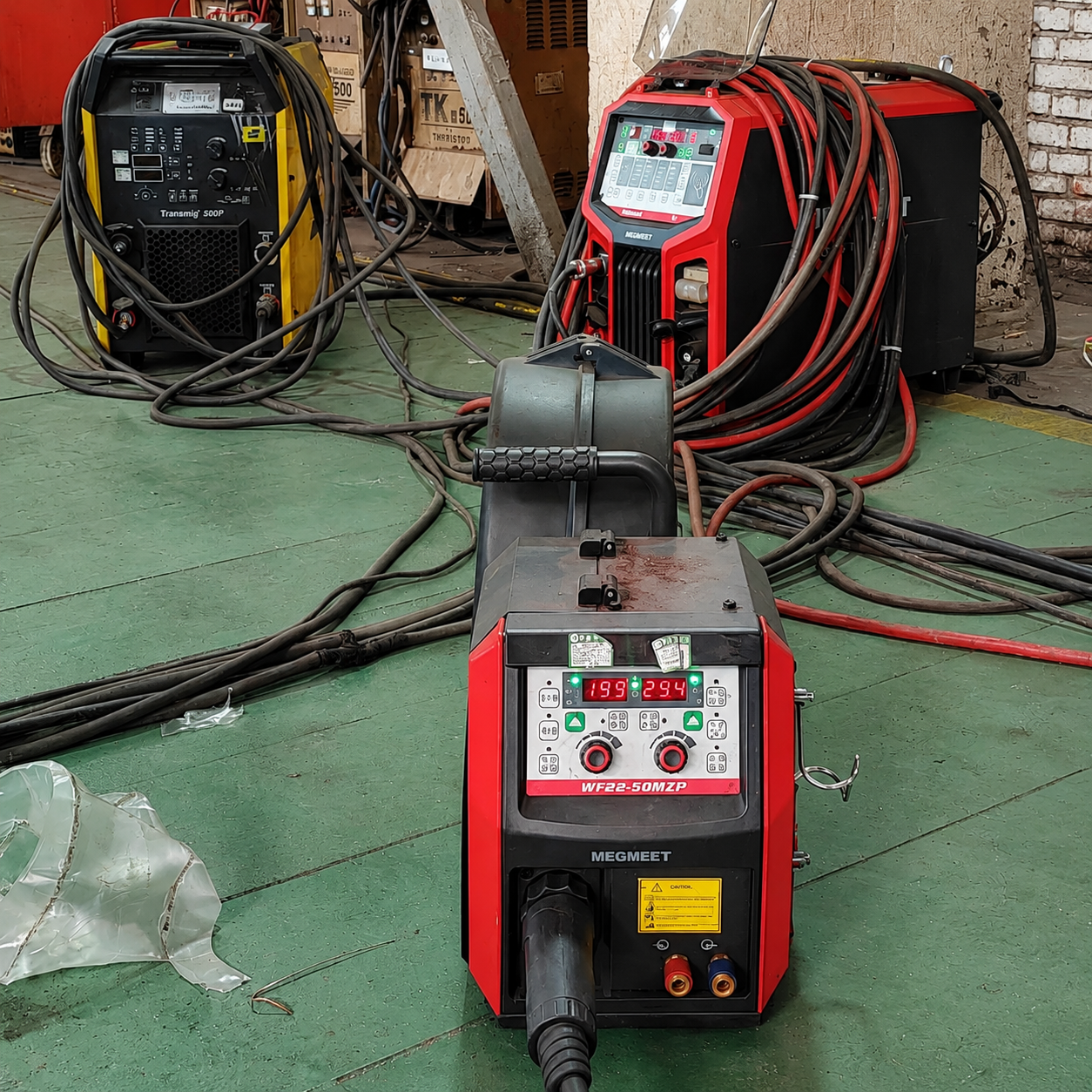
Find the restriction before adding force.
Do not immediately tighten the drive rolls, increase feed speed or pull hard on the wire. Those actions can crush soft wire, create a birdnest at the feeder or wedge a deformed section deeper into the guide. Release the feed force, locate the restriction and correct its cause.
Use the shutdown and service procedure specified for the exact welder and wire feeder.
If the rolls do not rotate in FEED or RETRACT, check controls, power and connections before opening the wire path.
Wrong roll, liner or guide size combined with a kink, tight bend, debris or excessive pressure can stop the wire.
Wire should move continuously, exit in the correct groove and pass a qualified coupon test before production.
Is the wire physically stuck—or is the feeder not being commanded?
“No wire at the nozzle” describes an observation, not a cause. Separate control, mechanical and weld-zone problems before changing parts. This prevents unnecessary nozzle replacement and reduces the chance of creating a second fault.
Confirm the wire-feed function is enabled, the feeder has power, connectors are fully seated and the manufacturer’s FEED/RETRACT or jog command is active. A dead feeder is not yet evidence of a blocked nozzle.
Look for spool overrun, an inlet-guide miss, birdnesting, excessive or insufficient roll pressure, an incorrect roll groove, a kinked conduit, contaminated liner or a blocked final guide.
If wire moves continuously yet does not enter the molten pool, inspect its exit position, angle, standoff and relationship to travel speed and laser power. That is a delivery or process problem, not a stuck-wire problem.
With lasing positively disabled and the equipment in the approved service state, use the model’s jog function. Observe whether the spool rotates, the drive rolls rotate, the wire moves at the feeder outlet and the wire emerges at the head. The first point where motion disappears is the most useful diagnostic boundary.
Do not place hands at the wire outlet while laser emission or automatic feed can start.
Follow the manufacturer’s shutdown, interlock, emergency-stop, stored-energy and service instructions. Let hot components cool, wear the required eye and hand protection, and keep the wire end directed away from people. Work inside a handheld laser system should be performed only by trained, authorized personnel. If the equipment cannot be placed in a verified non-emitting service state, stop and contact the supplier.
Recover the feed path in a controlled sequence.
Use the following steps as a diagnostic order, not as a substitute for the equipment manual. Stop when the fault is found. Replacing every component at once hides the root cause and makes recurrence more likely.
Stop, isolate and release the feeder force
Disable lasing and wire feed according to the manufacturer’s procedure. Note the displayed alarm, selected wire diameter, feed speed and the moment the jam occurred. Open or release the drive-roll pressure only after motion is prevented. This removes the force that may be compressing the wire against the blockage.
Inspect the feeder before touching the nozzle. A loop of wire around the rolls, crossed spool turns or a loose spool that has overrun points to a supply-side problem. Photograph the original routing and tension settings before changing them.
Remove the damaged wire with the approved feed/retract method
A kinked, mushroomed, oxidized or sharply bent end should not be forced through a precision guide. Use the equipment’s RETRACT function or the manual removal sequence specified by the manufacturer. If the procedure calls for cutting the wire, use a clean tool and make a straight, burr-free end before rethreading.
Do not yank a long wire backward through the complete liner while the drive rolls are clamped. Do not use the welding head as a lever. If the wire will not move after roll pressure is released, isolate the conduit and final guide to determine which section actually holds it.
Inspect the final wire guide or feeding nozzle
Remove the wire-feeding nozzle or guide tip only with laser emission disabled and by following the head-specific procedure. Check the bore for fused wire, spatter, scoring, an oval exit, impact damage and residue. A tip can look acceptable from the outside while a short restriction remains inside.
Replace a damaged or blocked part with the specified component. Never drill, file or randomly enlarge the bore: excess clearance allows the wire to wander, while an irregular edge can scrape wire and create a new jam. Confirm that the tip marking matches the installed wire system.
Match drive rolls, liner and nozzle to wire diameter
The complete delivery path must match the actual filler wire—not only the label on the spool. Verify wire alloy and diameter with the job specification, then check the drive-roll groove, inlet guide, liner or conduit and final guide/nozzle against the manufacturer’s parts chart.
Some systems group 0.8/1.0 mm and 1.2/1.6 mm components, but that arrangement is not universal. A narrow component can increase drag; an oversized roll groove can slip or flatten the wire unevenly. Use model-specific markings rather than a generic internet chart.
Straighten the conduit and inspect the liner
Lay the delivery conduit in the gentlest practical path. Remove tight loops, twists, crushing points and unsupported bends near the head. A wire may jog successfully through a straight conduit yet stall when the operator coils it tightly or turns the gun during production.
Inspect the liner for contamination, wear, a displaced end fitting or the wrong material. Steel wire debris and corrosion can raise drag; soft aluminum wire may require a low-friction liner and aluminum-compatible delivery parts. Clean or replace components only by the supplier’s method—generic solvent or uncontrolled shop air can introduce residue, moisture or debris.
Reset drive-roll and spool tension
Drive pressure must be high enough to move the wire without slipping, but not so high that it flattens, shaves or buckles the wire. Spool braking must prevent overrun when feed stops without forcing the motor to pull against excessive resistance. Change one setting at a time and record it.
If the rolls polish the wire but it does not move, more pressure may only worsen the jam. If the spool continues turning after the rolls stop, increase braking according to the feeder manual. If the wire forms a nest at the inlet, check alignment and downstream restriction before blaming the spool.
Align the wire at the welding head, jog it and prove the repair
Center the wire so it exits through the intended guide and enters the welding-nozzle groove or the manufacturer-defined weld position. The conduit should not pull the attachment sideways. With laser emission still disabled, use FEED and RETRACT to verify constant spool rotation, smooth wire motion and a repeatable exit point. Listen for surging and watch for wire shaving at the rolls or tip.
Do not return directly to a production part. Reinstall guards, restore the approved operating state and run a representative coupon with qualified laser, travel, shielding-gas and wire-feed parameters. Inspect bead continuity, wire incorporation, spatter, underfill, porosity indications and the condition of the wire tip after stopping. A free-moving wire path is necessary, but it does not prove the weld process is acceptable.
A jam at the nozzle may start meters upstream.
The feeder pushes wire through a coupled system. Small resistance at several locations can add up until the final guide becomes the apparent failure point. Inspect the path in the same direction the wire travels.
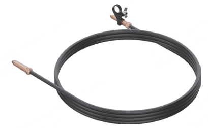
A tight bend increases liner friction and can make a correct guide tip appear undersized. Check routing before increasing roll pressure.
Wire-delivery conduit reference image: xTool MetalFab wire-feeder guide.
Spool and inlet
Confirm the spool turns in the specified direction, the wire approaches the inlet without crossing another turn, the hub brake is correct and the wire enters the inlet guide rather than rubbing its edge.
Drive rolls and conduit
Verify groove size and geometry, roll alignment, pressure, liner type, connector seating, conduit length and bend radius. Look for shavings that identify where abrasion begins.
Guide tip and weld position
Inspect the final bore, attachment alignment, wire angle, standoff and exit location. The wire must enter the intended pool position without touching an unintended surface.
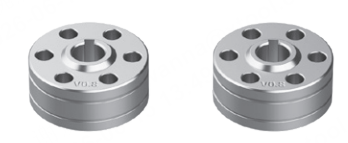
The drive-roll marking is a setup control.
Correctly sized rolls grip the wire without forcing it into the wrong groove. The roll profile also matters: equipment suppliers may specify different geometries for steel and soft aluminum wire. Treat the marking, orientation and material recommendation as part of the qualified setup.
Read both the wire-spool label and the roll marking; do not rely on memory.
Confirm the active groove is the intended one after the roll is installed.
Inspect for metal dust or grooves that have become polished, sharp or uneven.
After adjustment, jog the wire through the complete head—not only past the rolls.
Use the symptom to choose the next check.
Several different faults can produce the same complaint. The table keeps the investigation focused and highlights actions that commonly make the problem worse.
| Observed symptom | Likely area | Next controlled check | Avoid |
|---|---|---|---|
| No roll movement or power indication | Feed enable, power, control cable, interlock or feeder fault | Verify enable state, connectors, power indicator and approved FEED/RETRACT command. | Opening the nozzle or tightening rolls before proving the feeder is commanded. |
| Rolls turn and slip on stationary wire | Downstream restriction, wrong groove or too little pressure | Release pressure; isolate conduit and guide; inspect roll size and wire surface. | Increasing pressure until the wire is flattened or shaved. |
| Wire nests beside the rolls | Inlet misalignment, excessive pressure, soft wire or blocked conduit | Remove damaged wire, check inlet/roll alignment and test the conduit separately. | Trying to feed the birdnest through the liner. |
| Wire moves with conduit straight but stalls when bent | Tight routing, damaged liner, wrong liner size or debris | Simplify routing and inspect the liner, connectors and end fittings. | Coiling the conduit tightly to keep the work area tidy. |
| Wire reaches the head but stops at the final guide | Blocked, worn, damaged or mismatched guide/nozzle | Remove by the approved procedure and inspect the bore and part marking. | Drilling, filing or heating the component to force clearance. |
| Wire surges or curls after exiting | Intermittent drag, excessive roll force, wire cast or guide misalignment | Check the whole path, wire condition and exit alignment; jog at low approved speed. | Compensating with a large feed-speed change. |
| Wire exits steadily but is not incorporated | Wire angle, groove position, standoff or process parameters | Align the wire to the defined weld point and validate on a coupon. | Calling it a nozzle jam when mechanical feed is stable. |
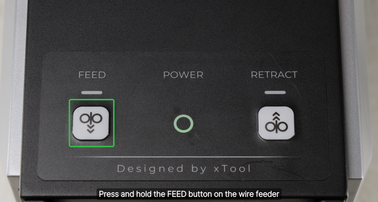
Jogging proves motion—not weld quality.
Use the equipment’s dedicated FEED and RETRACT controls only as described in its manual. Smooth motion in both directions helps confirm the feeder, liner and guide are mechanically clear. It does not verify filler placement, penetration, fusion or shielding.
Confirm guards and components are installed as required for the jog test.
Keep the outlet aimed into a controlled area and hands away from the moving wire.
Watch for constant spool rotation and an unchanged exit point at the head.
Then validate with a representative coupon and the approved welding procedure.
Steel and aluminum do not fail in exactly the same way.
The diagnosis order remains the same, but filler-wire stiffness and surface condition change which part of the system is most sensitive. Use the consumables and setup specified for the wire alloy.
Watch for rust, shavings and liner contamination.
Stiffer wire often transmits feeder force farther down the conduit, so a restriction at the final guide can produce roll slip or a sudden buckle at the inlet. Corroded or dirty wire increases drag and deposits debris in the liner.
- Reject wire with rust, heavy dirt, severe kinks or damaged spool edges.
- Check for metallic dust near the rolls and at liner ends.
- Do not assume a steel liner is suitable for every feeder and wire type.
Protect soft wire from crushing and high friction.
Aluminum wire deforms more readily. Excessive roll pressure, a sharp inlet, the wrong roll geometry or a high-friction liner can shave or flatten it. The damaged section may then wedge in a guide that works correctly with undamaged wire.
- Use the low-friction liner and roll type specified by the supplier.
- Keep the conduit path gentle and minimize unnecessary length.
- Reset pressure after changing alloy or diameter; do not copy the steel setting.
Do not infer compatibility from nominal diameter alone. Confirm the wire alloy, temper, surface coating, roll geometry, liner and final guide with the equipment supplier, then prove the combination on representative material.
Replace the cause—not every part on a calendar.
Service intervals depend on wire type, duty cycle, environment, conduit movement and the equipment maker’s instructions. Use visible condition and repeatable feed performance alongside the maintenance schedule.
Replace the guide/nozzle
Replace it when the bore is blocked and cannot be restored by the approved method, the exit is oval or damaged, the part has overheated, the wire position is no longer repeatable or the marking does not match the required setup.
Replace the liner or conduit
Replace it when it is kinked, crushed, contaminated beyond approved cleaning, internally worn, incorrectly sized, fitted with damaged ends or produces high drag even when routed gently.
Replace rolls or wire
Replace rolls with sharp, worn or damaged grooves. Quarantine wire that is rusty, dirty, badly cast, kinked, flattened, shaved or associated with a damaged spool. Do not feed suspect wire into a new liner.
Know when to stop troubleshooting.
Stop immediately when
- Laser emission cannot be positively disabled.
- Interlocks, emergency stop or protective housing appear damaged.
- The feeder energizes unexpectedly or alarms recur after reset.
- The conduit, connectors or head show heat, arcing or electrical damage.
- Wire has fused into a component that the manual does not authorize the operator to remove.
Prepare useful evidence for service
- Welder, head and wire-feeder model and serial information.
- Filler alloy, diameter, spool brand and lot if available.
- Photos of roll markings, liner/conduit, guide tip and wire damage.
- A short video of FEED/RETRACT behavior with lasing disabled.
- Displayed alarms, feed speed, job duration and the point in the cycle where the fault begins.
- Whether the problem changes when the conduit is straightened or the final guide is removed by the approved procedure.
Send the wire, feeder and welding-head details.
Oceanplayer can review your filler-wire diameter, material, roll and liner setup, wire-feeding nozzle, application photos and target weld. The result is a clearer parts list and a practical validation plan—not a generic pressure or feed-speed number.
Related welding resources
Welding wire jam FAQ
Why is my welding wire stuck in the nozzle?
Common causes include damaged or rusty wire, a mismatched wire guide, blocked or worn nozzle, wrong drive-roll groove, excessive roll pressure, spool overrun, a kinked conduit, contaminated liner or misalignment at the welding head. First confirm the feeder is actually enabled and commanded.
Can I pull the stuck wire out with pliers?
Do not improvise while the rolls are clamped or the feeder and laser can energize. Use the manufacturer’s retract or manual removal procedure. Pulling hard can damage the liner, head attachment or guide and may leave a deformed section trapped inside.
Should I increase drive-roll pressure when wire stops?
Not until the downstream path is checked. More pressure may flatten soft wire, create shavings or form a birdnest while the blockage remains. Set pressure only to the manufacturer’s method after rolls, liner, conduit and final guide are confirmed.
Can I drill the nozzle hole larger?
No. An enlarged or irregular bore reduces positional control and may scrape the wire. Replace the guide/nozzle with the specified part for the wire diameter and system rather than modifying a precision consumable.
How do I tell whether the nozzle or liner is blocked?
With laser emission disabled and the machine in its approved service state, release the roll force and isolate sections according to the manual. If wire moves through the liner after the final guide is removed, inspect the guide. If it remains tight, inspect the conduit, liner and connectors.
Why does wire feed when straight but jam during welding?
The conduit may be bent or twisted more tightly in the working position. Gun movement can also pull the wire attachment sideways. Re-route and support the conduit, then verify free feed across the full operating envelope.
Why does aluminum wire jam more easily?
Aluminum filler is softer and more easily flattened, shaved or buckled by excessive roll pressure, the wrong roll geometry, a rough inlet or high liner friction. Use the supplier-specified low-friction liner and aluminum-compatible delivery parts.
What is birdnesting at the wire feeder?
Birdnesting is a tangle or buckle of wire near the drive rolls. It typically means the rolls continued pushing against a downstream restriction, or the wire missed the intended inlet path. Remove the damaged wire and find the restriction before rethreading.
What if the drive rolls do not rotate?
Check feed enable, touchscreen settings, feeder power, connectors, status indicators and the approved FEED/RETRACT command. If the controls and connections are correct but the feeder remains inactive, stop and contact service.
Why does the wire emerge but miss the weld pool?
The guide may be misaligned, the conduit may pull the attachment sideways, or the wire angle and standoff may be wrong. Align the wire with the manufacturer-defined welding-nozzle groove and weld point, then validate on a coupon.
How often should the nozzle and liner be replaced?
Follow the equipment maker’s maintenance schedule and inspect by condition. Replace parts that are blocked, worn, damaged, contaminated beyond approved cleaning, mismatched or no longer provide stable, repeatable feed.
When is a test weld required after clearing a jam?
Always verify the repair on a representative coupon before returning to production. Smooth jogging confirms mechanical motion only; the test weld confirms filler placement and the combined laser, travel, shielding and wire-feed settings.
Sources used for this guide
Component names and procedures differ by manufacturer. These sources support the diagnostic framework; the manual for the installed machine remains the controlling document.
- xTool Support — Troubleshooting wire not feeding from the welding head
- xTool Support — Wire feeder installation and use guide
- xTool Support — MetalFab wire-feeder and welding-head setup
- Miller Electric — OptX handheld laser welding system owner’s manual
- Miller Electric — OptX wire feeder owner’s manual
- Miller Electric — OptX wire delivery guide attachment
- Miller Electric — Handheld laser wire liners