oceanplayer

Oceanplayer Industrial Laser Equipment | Cleaning, Welding, Marking, Automation Sample Testing | Free Engineering Tools | Global Shipping
Main Systems
Best Seller Oceanplayer 500W pulsed laser cleaning machine
Featured Model
500W Pulsed Laser Cleaner

Higher pulse cleaning speed with controlled surface impact.

500W PulsedFine ControlBest Seller
Engineering Tools
Applications
Industries
Company
Resources
Welding Process ComparisonEngineering Buyer GuideUpdated July 2026
From discrete nuggets to continuous seams

Spot Welding vs Laser Welding

Spot welding is usually the practical route for repeatable lap joints when both sides are accessible. Laser welding is often the more suitable candidate for one-sided access, narrow or continuous seams, flexible automation, low-distortion potential and demanding appearance or sealing goals. Neither method is universally faster, stronger or cheaper.

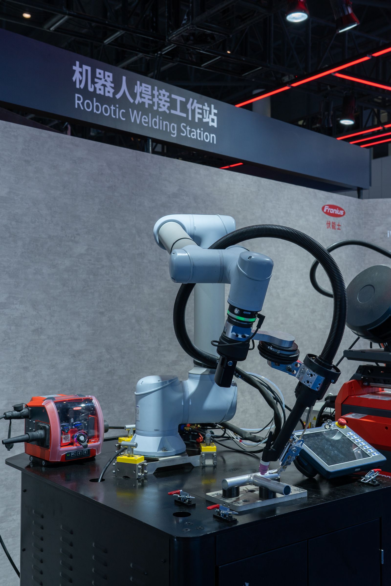
Automated robotic welding station in an industrial production cell
Compare the whole production cell—not only the heat source.Joint geometry, access, clamping, cycle time, inspection, maintenance and safety decide the qualified cost per part.Photo: Peter Xie, via Pexels; display cropped.
Spot-welding advantage

Repetitive overlap joints

Fast discrete attachments, mature automation and a well-established process window for conductive sheet stacks.

Laser-welding advantage

Precise seam control

One-sided optical access, continuous paths, narrow fusion zones and flexible programmed motion.

Fastest eliminator

Can both sides be reached?

Conventional resistance spot welding normally needs opposing electrodes; laser welding needs line-of-sight from one side.

Engineering rule

Qualify the joint, not the process name

Fused area, defects, load direction, fatigue, leak criteria and repeatability determine whether a weld is acceptable.

Direct Answer

Which process should you choose?

Choose resistance spot welding first when the design already uses overlapping conductive sheet, opposing electrodes can reach the joint, discrete nuggets meet the structural requirement and the product is stable enough to justify a dedicated gun-and-fixture setup.

Choose laser welding first when the part needs a continuous or visually clean seam, access is available from only one side, distortion and post-processing must be minimized, the path is complex or product variants need programmable flexibility.

Compare both on coupons when material or coatings are difficult, annual volume is high, the joint is fatigue-critical, or replacing many spot welds with a laser seam changes the load path. The valid comparison uses the same part, acceptance criteria and total cycle—not two idealized brochures.

Comparison at a Glance

Different energy, access and joint output.

“Spot welding” here means resistance spot welding (RSW). “Laser welding” means industrial laser beam welding (LBW), which can create isolated spots or a continuous seam. The table describes common production arrangements, not universal limits.

Decision factorResistance spot weldingLaser weldingWhy it matters
Heat-generation methodElectrical resistance at the sheet interfaces while electrodes apply force.Focused optical energy absorbed by the workpiece; no opposing electrode force.Each process has different critical variables and failure modes.
Typical joint outputDiscrete fused nuggets in an overlap stack.Discrete spots or continuous butt, lap, edge and fillet-style seams.A continuous seam can change stiffness, fatigue and sealing behavior.
AccessNormally requires opposing electrodes on both sides.Normally needs one-sided optical line-of-sight plus room for the head/nozzle.Access can eliminate a process before cost or speed is discussed.
Fit-up behaviorElectrode force clamps the overlap locally; stack variation still changes resistance and nugget growth.Autogenous seams are commonly sensitive to gap, mismatch, focus and seam position.Laser may require better edges, tracking and fixturing.
Heat and distortionHeating is localized at every nugget, but many spots and gun force affect the assembly.High power density can produce a narrow fusion/heat-affected zone; long seams still shrink.“Laser means no distortion” is not a responsible design assumption.
Surface resultElectrode indentation and visible spot marks may be acceptable or hidden.A narrow, smooth seam is possible when fit-up, shielding and parameters are controlled.Visible products may avoid grinding or cover panels.
Routine maintenanceElectrode dressing, alignment, cooling and cap replacement.Protective windows, optics cleanliness, nozzle condition, cooling and beam alignment.Maintenance allowance belongs in takt and cost calculations.
AutomationMature fixed and robotic guns for highly repetitive sheet assemblies.Robot, gantry or scanner paths can change in software but need integrated beam safety.Flexible motion may reduce dedicated stations for product variants.
SealingSeparate nuggets do not inherently close the path between welds.A continuous seam can be designed and qualified for a leak-tight target.Leak testing and seam start/stop quality remain required.
Investment tendencyOften lower for a simple dedicated station; a large servo-gun line is still substantial capital.Usually higher once source, motion, enclosure, interlocks, extraction and monitoring are included.Compare complete cells and qualified cost per part.
Process Fundamentals

How each weld is actually formed.

Both processes melt metal, but they create and control the molten zone in different ways. Understanding that mechanism explains the differences in joint design, access, maintenance and inspection.

Diagram showing electrodes clamping overlapping sheets during resistance spot welding
Resistance Spot Welding

Force + current + time form a nugget.

Copper-alloy electrodes clamp overlapping sheets. A controlled high current flows through the stack, and resistance concentrates heat at the faying interfaces. The molten nugget grows, then solidifies while electrode force is maintained.

  1. Align the overlap stack and close the electrodes.
  2. Reach the programmed force before applying current.
  3. Deliver the qualified current schedule and weld time.
  4. Hold force while the nugget solidifies, then open the gun.
Illustration: Himanshu19s, via Wikimedia Commons, CC BY-SA 4.0; displayed without alteration.
Industrial laser welding test showing beam delivery, shielding and fume removal nozzles
Laser Beam Welding

Power density + motion form a spot or seam.

The workpiece absorbs focused optical energy. At lower power density the process can operate in conduction mode; at higher power density a vapor cavity can support keyhole-mode penetration. Fixturing remains critical even though opposing electrodes are not used.

  1. Clean, align and clamp the real production joint.
  2. Set focus, spot size, power mode, speed and shielding.
  3. Track the joint while controlling wobble or filler, if used.
  4. Control starts/stops, plume, solidification and inspection.
Photo: Krorc, via Wikimedia Commons, CC BY-SA 3.0; display cropped.
No transferable “standard setting” exists for either process.

Spot-weld quality depends on current, force, time, electrode geometry, coating, stack and cooling. Laser-weld quality depends on source and beam delivery, focus, spot, speed, seam position, joint gap, metallurgy, shielding and filler strategy. Published values are starting evidence only when the exact system and joint are identified.

12 Key Differences

The process choice changes the whole joint system.

These differences are more useful than a generic list of advantages and disadvantages because each one maps to a drawing, fixture, takt-time calculation, acceptance test or safety requirement.

01 / Energy

Resistance heating vs optical absorption

Spot welding generates heat from electrical resistance while electrode force maintains contact. Laser welding depends on how a focused beam couples into the material. Electrical conductivity, contact resistance, absorption, wavelength and surface condition therefore influence the two processes differently.

02 / Joint geometry

Overlap nuggets vs flexible seam shapes

Conventional spot welding strongly favors overlapping sheets with enough flange for electrodes and the required weld pitch. Laser welding can follow butt, lap, edge, corner and selected fillet-style paths. Changing from spots to a seam may require a structural redesign, not a machine substitution.

03 / Access

Two-sided force vs one-sided line-of-sight

A direct spot-welding gun normally places electrodes on opposite sides and the part must react the closing force. Laser welding generally needs access from one side, but the head, nozzle and safe beam path still need clearance. Root shielding, backing or inspection may still create secondary access requirements.

04 / Joint output

Discrete load points vs a continuous fused path

A spot pattern transfers load through individual nuggets and the sheet between them. A laser can produce points or a continuous seam. Seam length, start/stop design and fused width alter stiffness, fatigue, corrosion paths and leak behavior. More fused length is not automatically better if restraint or metallurgy is unfavorable.

05 / Takt time

Milliseconds per spot is not total cycle time

Spot weld formation can be extremely quick, but every location requires gun closure, current, hold, opening and robot indexing. A laser may traverse a long path continuously, yet clamping, tracking, shielding and inspection remain. Compare loading-to-unloading time plus maintenance allowance.

06 / Thermal result

Laser can concentrate heat more tightly

High laser power density can create a small molten volume and narrow heat-affected zone, supporting low-distortion production. Wobble, filler, slow travel, long seams or repeated passes add heat. Spot welding localizes each nugget, but a dense pattern and electrode force can still move or mark thin sheet.

07 / Strength

No process name guarantees a stronger joint

Spot-weld strength depends on nugget diameter, number, pitch, sheet strength and load direction. Laser-seam strength depends on fusion width, penetration, defects, HAZ and seam path. Compare tensile-shear, cross-tension, peel, fatigue, leak and service loads using equivalent acceptance criteria.

08 / Fit-up

Local clamping vs seam-position control

Opposing electrodes help close an overlap locally, although coatings, stack thickness and interface gaps still shift the weld window. Autogenous laser seams commonly require controlled gaps and mismatch. Beam oscillation or filler can improve tolerance, but they change the qualified thermal and geometric window.

09 / Surface and coatings

Both processes react to what is on the metal

Galvanized steel can accelerate spot-electrode wear and change current requirements. In a closed laser lap joint, zinc vapor can disrupt the keyhole unless the joint provides a controlled escape path. Oil, oxides, plating and unknown coatings can affect both weldability and fume hazards.

10 / Maintenance

Electrode caps vs the optical train

Spot lines track cap diameter, alignment, dressing, water cooling and current stepping. Laser cells track protective-window condition, nozzle alignment, focus, beam delivery and chiller health. A process with no filler is not maintenance-free. Drift controls must be designed into production.

11 / Automation

Dedicated maturity vs programmable flexibility

Automated spot welding is deeply established in body-in-white and appliance production. Laser paths can be reprogrammed and routed through complex geometry, while scanners can minimize mechanical repositioning. Laser integration also adds enclosure, interlocks, seam tracking and reflected-beam risk management.

12 / Facility safety

Both are industrial hazards; laser adds Class 4 controls

Resistance welding brings high current, pinch/crush points, hot metal, expulsion and fumes. Open-beam industrial laser welding adds direct and reflected eye/skin hazards, fire risk and laser-generated airborne contaminants. Laser glasses are supplementary—not a substitute for containment and interlocks.

Strength and Joint Design

“Which is stronger?” is the wrong first question.

Start with the required load path and failure mode. Then size and qualify the nugget pattern or seam geometry that satisfies the part—not a generic process comparison.

A spot pattern has discrete effective area

Resistance spot welds carry load through individual nuggets. Nugget diameter, sheet thickness, spacing, distance from the sheet edge and number of spots affect how load enters the surrounding sheet. In lap-shear loading, a sound nugget may pull a button from the sheet; in peel or cross-tension, the same joint can be much less favorable. Closely spaced spots can also shunt current through earlier welds, changing later nugget growth.

A laser seam creates a different structural member

A laser seam can distribute load over a longer fused path and can reduce flange width, but it also introduces continuous shrinkage and a heat-affected path. Penetration, underfill, porosity, cracking, start/stop quality and local mismatch all influence effective section. A narrow attractive top bead is not proof of root fusion or fatigue life.

Use matched tests, not visual impressions

For a responsible replacement study, test both joint concepts in the same material lot, coating condition, thickness and production fixture. Evaluate the loads the product actually sees: tensile shear, cross tension, peel, torsion or bending, fatigue spectrum, leak pressure, electrical resistance, corrosion and impact where relevant. A destructive coupon that merely separates at a high force may still hide unacceptable scatter or fatigue behavior.

Do not replace ten spots with one laser line by weld length alone.

The change can alter stiffness, crack propagation, galvanic paths, coating damage, repairability and assembly sequence. A designer and welding engineer should define the new acceptance criteria before equipment selection.

Speed and Throughput

Calculate total part cycle—not source speed.

Laser travel speed and spot-weld time use different units, so quoting them side by side does not answer which cell makes more accepted parts per shift. Map every production event and maintenance stop.

01

Load and locate

Part presentation, datum repeatability, identification and operator/robot handling.

02

Clamp and verify

Gun closure or fixture clamping, gap closure, sensor checks and safety authorization.

03

Join

Spot current/hold plus indexing, or laser travel plus acceleration, corners and starts/stops.

04

Inspect

Process signatures, vision, seam monitoring, destructive sampling and leak checks.

05

Unload

Fixture release, part transfer, cooling allowance and downstream handling.

06

Maintain

Electrode dressing/cap changes or protective-window/nozzle cleaning and verification.

Total cycle time = load + locate + clamp + weld/index + inspect + unload + planned maintenance allowance

Spot welding can win when a stable gun rapidly makes a simple pattern. Laser can win when one continuous path replaces repeated indexing, one-sided access removes a handling station, or less distortion and finishing reduce downstream time. The result belongs to the real cell simulation and coupon data.

Material Suitability

Material behavior can reverse the obvious choice.

Do not transfer a process window between grades because the trade name sounds similar. Electrical resistance, thermal conductivity, absorption, coating, hardenability, oxide stability and solidification range all matter.

Low-carbon steel

Both processes are well established. Spot welding is a natural fit for high-volume lap stacks. Laser welding becomes attractive for continuous seams, reduced flange width or one-sided access.

Spot risk
Electrode wear, expulsion, shunting and stack variation.
Laser risk
Gap sensitivity, focus error and seam-position drift.

Galvanized steel

Zinc changes both processes. Spot welding often needs a coating-specific current/force window and electrode maintenance. A laser lap seam needs a controlled strategy for zinc vapor escape.

Spot risk
Cap alloying, shortened electrode life and expulsion.
Laser risk
Porosity, blowholes and spatter from trapped vapor.

Stainless steel

Spot welding remains economical for hidden lap attachments. Laser welding is often favored for narrow visible seams, precision assemblies and low-distortion potential.

Spot risk
Indentation, surface marks and localized corrosion details.
Laser risk
Undercut, focus/gap error and alloy-specific cracking.

Aluminum alloys

High electrical and thermal conductivity complicate resistance heating; stable high current, force, surface control and electrode condition are important. Laser welding must manage oxide, absorption, keyhole stability, porosity and alloy crack sensitivity.

Decision
Qualify the exact alloy/temper and surface, not “aluminum” generally.

Copper and busbars

Very high conductivity makes heat balance difficult for resistance welding. Infrared-laser absorption and back-reflection can also be challenging; wavelength, beam quality, geometry and monitoring strongly affect feasibility.

Decision
Electrical resistance and heat damage may be as important as mechanical strength.

Dissimilar metals

Selected combinations can be joined by carefully controlled resistance or laser processes, but brittle intermetallic layers, dilution, thermal expansion and galvanic corrosion can dominate the design.

Decision
Treat every metal pair, thickness ratio and service environment as an engineering-review case.
Thickness is a process window, not a single limit.

ISO scopes describe the applications covered by a standard; they do not define the physical limit of every machine and material. Available current/force, electrode geometry, stack ratio, beam quality, focus, travel speed, joint design and acceptance criteria all change usable thickness.

Production Applications

Choose by the part’s job—not industry fashion.

Automotive, appliances, batteries and precision fabrication can use both processes. The correct route is determined by the specific joint, access, acceptance evidence and factory economics.

Industrial robot equipped for resistance spot welding

Where spot welding normally leads

Body-in-white lap joints, cabinets, appliances, trays, brackets and stable sheet assemblies where discrete nuggets meet the drawing and both sides remain accessible.

Photo: Mukszwei, via Wikimedia Commons, CC BY-SA 4.0; display cropped.

Where laser welding normally deserves a trial

  • Visible stainless fabrication: narrow seams and reduced finishing can matter more than the lowest source price.
  • Battery and electrical assemblies: precise energy placement and monitoring can support selected tab, terminal and busbar designs.
  • Sensors and small components: one-sided access and low heat input can protect dimensional or functional features.
  • Continuous sealed products: a qualified seam can address leak paths between discrete fasteners or nuggets.
  • Mixed-product automation: reprogrammable paths may reduce dedicated tooling when joint families remain controllable.
  • Reduced flange designs: non-contact beam access may allow narrower joint geometry, subject to structural validation.
Battery manufacturing is not one application.

Cell format, tab/busbar material, coating, electrical resistance, allowable heat, weld monitoring and service vibration can favor different joining methods. Do not select by the word “EV” alone.

Capital and Cost per Part

Compare complete, safe, qualified cells.

A low equipment quote can become expensive after fixtures, utilities, guarding, extraction, quality monitoring and rework are included. Build both alternatives around the same production target.

Cost elementSpot-welding cellLaser-welding cellBuyer question
Core equipmentPower supply, transformer, gun/electrodes, force control and water cooling as required.Laser source, delivery fiber/head, motion system, cooling and shielding delivery.Is the quote a source only or a production-ready cell?
SafetyElectrical guarding, pinch-point protection, spark shield and extraction.Class 4 enclosure/barriers, interlocks, controlled access, beam stops, extraction and fire controls.Who owns the final risk assessment and validation?
ToolingFlanges and access for the gun; support against electrode force; cap clearance.Precision datum control, gap/mismatch management, beam access and possible seam tracking.Can the existing drawing be fixtured repeatably?
Consumables and maintenanceElectrode caps, dressers, cooling water and planned alignment/current checks.Protective optics, nozzles, shielding gas, filters and beam/focus verification.What is the planned maintenance interval at target volume?
Quality controlCurrent/force/time signatures, electrode condition, peel/chisel or mechanical sampling.Power/speed/focus/seam data, vision or optical monitoring, macrosections and NDT as required.How is process monitoring correlated to destructive evidence?
Downstream workSpot marks may be hidden, filled or covered; distortion correction depends on pattern.A clean seam may reduce grinding, polishing or straightening, but only when quality is stable.Which downstream steps actually disappear?
ChangeoverGun/electrode/fixture changes can be fast for a stable product family.Software paths are flexible; fixture, focus, head clearance and safety validation still change.How many variants share the same validated setup?
Calculate qualified cost—not theoretical weld cost.

Use accepted parts per hour, including scrap, rework, inspection, planned maintenance and downtime. Laser can justify higher capital when it removes stations or downstream work; spot welding can remain the better investment when a simple nugget pattern already meets every requirement.

Interactive Planning Tool

Which welding process fits your part?

Choose the closest production conditions. The result identifies a starting route and the main validation risk; it does not replace a joint drawing review or qualified welding procedure.

Planning recommendation

Start with resistance spot welding

The default inputs describe a stable lap stack, two-sided access and discrete attachments—conditions that align well with resistance spot welding.

  • Opposing electrodes can reach the joint.
  • The overlap and discrete attachment suit nugget-based design.
  • A fixed high-volume product can justify dedicated gun tooling.
Main validation riskConfirm current, force, weld time, electrode geometry, nugget size and failure mode on the actual stack.
Defects and Inspection

Monitor the process, then prove the joint.

In-process signals can reveal drift, but a current trace or optical signal is not automatically proof of penetration, nugget size or strength. Correlate monitoring with sections and application-relevant testing.

Common spot-welding problems

  • Undersized or missing nugget: insufficient heat, poor contact, shunting, alignment or stack variation.
  • Expulsion: excessive energy, inadequate force, contamination, gap or unstable contact.
  • Indentation and marking: force, heat, cap size/shape and surface temperature interact.
  • Electrode sticking: cap material, cooling, coating pickup and current density need review.
  • Drift over a run: cap wear changes contact area and current density even when the program is unchanged.
  • Useful evidence: dynamic process data, cap inspection, nugget section, peel/chisel, tensile-shear or cross-tension testing as applicable.

Common laser-welding problems

  • Lack of fusion or penetration: focus, power density, speed, gap, beam position or contamination may be wrong.
  • Porosity: keyhole instability, gas entrapment, oxide, coating vapor or inadequate preparation can contribute.
  • Undercut or underfill: speed, beam distribution, seam tracking, gap and filler strategy need review.
  • Hot or solidification cracking: alloy chemistry, dilution, restraint and thermal cycle must be controlled.
  • Spatter and optics contamination: plume direction, keyhole behavior, nozzle/extraction and protective-window strategy interact.
  • Useful evidence: logged beam/motion data, visual and dimensional checks, macrosections, NDT, mechanical, fatigue and leak testing as required.
Resistance spot welding schematic with magnified aluminum weld nugget microstructure

Section evidence turns a surface mark into a measurable joint.

Macro- or microsection work can reveal nugget/fusion geometry, penetration, voids and interface behavior that the external surface cannot prove. Use the specimen preparation and acceptance route required by the product specification.

Illustration: Sung-Min Wi, via Wikimedia Commons, CC BY 4.0; displayed without alteration.
Procedure and Acceptance

Specify the evidence before production.

Standards are selected by material, process, product code, contract and jurisdiction. The references below are useful anchors, but the responsible engineer must define which editions and acceptance criteria govern the actual assembly.

Resistance WPS

ISO 15609-5

Defines the content expected in a resistance-welding procedure specification. Record the variables that control nugget geometry, pattern and properties—not only machine program numbers.

Resistance qualification

ISO 15614-12:2021

Defines procedure-test conditions and validity limits for spot, seam and projection welding. It helps separate a proven production range from an attractive one-off sample.

Spot-weld testing

ISO 10447:2022

Covers peel and chisel testing of resistance spot and projection welds within its stated scope. Mechanical test standards such as ISO 14272 and ISO 14273 address cross-tension and tensile-shear specimens.

Laser WPS

ISO 15609-4:2009

Specifies content for a laser beam welding WPS, including variables that influence the quality and properties of the welded joint.

Laser qualification

ISO 15614-11:2025

Sets requirements for qualification testing of electron- and laser-beam welding procedure specifications for metallic materials. Confirm the corrected 2026 issue when procuring the document.

Laser imperfections

ISO 13919-1 / -2

Provide laser-weld imperfection quality levels for defined material families. ISO states that these production quality levels are not by themselves fitness-for-purpose ratings.

AWS starting data are not final production settings.

AWS C1.1M/C1.1:2019-AMD1 explicitly positions its resistance-welding data and procedures as starting points from which users establish acceptable settings for specific production applications.

Safety and Facility Planning

A laser cell needs more than a welding curtain and glasses.

Both processes require a formal risk assessment, engineered safeguards, trained personnel, maintenance controls and source-capture ventilation appropriate to the actual materials and coatings.

Resistance spot-welding controls

Plan for electrical isolation and grounding, guarded live parts, protected initiating controls, gun pinch/crush points, hot material, expulsion and sparks. Machine guarding must not create new trapping hazards during loading or electrode maintenance. Cooling-water condition, cables, force systems and interlocks belong in the periodic inspection plan. Coatings, oils and production rate determine the required fume evaluation and ventilation.

Class 4 laser-welding controls

Industrial welding lasers are commonly Class 4 at the source or during service. OSHA identifies direct and reflected eye/skin exposure and fire as immediate concerns; laser-material interaction can also generate airborne contaminants and plasma radiation. Use engineered containment wherever feasible, interlocked access, controlled-area rules, trained and authorized personnel, beam termination, management of specular reflections, warning systems and wavelength-/optical-density-specific eye protection.

Eyewear is the last line, not the enclosure

Protective eyewear must match the actual wavelength, exposure and required optical density, and it must preserve enough visible transmission for the task. It does not control an unexpected beam leaving the work area, a reflection toward an unprotected person, or a fire. Handheld laser welding deserves the same Class 4 hierarchy as an automated open-beam process.

Control the plume at the source

Fume composition depends on base metal, coating, filler, oil, paint and process intensity. Design extraction around the actual plume without disturbing shielding gas or pulling contamination across optics. Hazardous coatings or unknown plated parts require material identification before welding.

Do not select a laser process until the safe operating concept is credible.

If the part cannot be enclosed, reflections cannot be controlled, access cannot be interlocked or extraction cannot capture the process plume, treat the proposed installation as an unresolved engineering risk—not a PPE problem.

Replacement Study

Can laser welding replace your spot-welding operation?

Sometimes—but a credible study starts with the joint requirement and production evidence. Follow this sequence before comparing machine prices.

Freeze the current baseline

Document material/coat lots, stack, spot count and pitch, cycle time, cap life, scrap, rework, inspection and actual failure modes.

Define the required outcome

State static, peel, fatigue, leak, electrical, corrosion, appearance and dimensional criteria rather than “same or stronger.”

Redesign the joint deliberately

Establish seam path, overlap or edge design, gap/mismatch tolerance, start/stop position, flange requirement and safe beam access.

Build a controlled coupon matrix

Challenge material, coating, gap, focus and fixture tolerance—not only nominal zero-gap samples with the best surface finish.

Test the real load path

Use sections and product-relevant mechanical, fatigue, leak, electrical or corrosion tests. Record scatter and failure mode.

Simulate the complete cell

Include handling, clamping, safety logic, tracking, inspection, maintenance and downstream finishing in takt and cost.

Qualify the procedure

Issue the applicable WPS and procedure qualification evidence with controlled variables, validity limits and acceptance criteria.

Release with monitoring

Correlate in-process signals to destructive evidence, set reaction plans and audit optics, electrodes, fixtures and calibration.

Useful review package

Send the material grade and coating, thickness of every layer, joint drawing and tolerances, real part photos, seam length or spot count, load/fatigue/leak criteria, annual volume, takt target, current defects and available floor/safety constraints.

Application Review

Compare the joint on your actual parts.

Oceanplayer can review laser-welding feasibility against your material, access, seam goal and production target, then define a sample-test direction. Final production release still requires the governing qualification and acceptance evidence.

Include these details
  • Material grade, coating and surface condition
  • Thickness of each layer and joint drawing
  • Required load, fatigue, leak and appearance criteria
  • Current spot pattern, cycle and defect problem
  • Annual volume, variants and automation target
  • Photos, CAD screenshots or physical samples
Frequently Asked Questions

Spot welding vs laser welding

Short answers to the questions buyers and manufacturing engineers ask before a trial.

What is the main difference between spot welding and laser welding?

Resistance spot welding forms discrete nuggets by combining electrical resistance heating with electrode force on an overlap stack. Laser welding uses a focused beam to create isolated welds or continuous seams, normally with one-sided optical access and no opposing electrode force.

Is laser welding stronger than spot welding?

Not automatically. Strength depends on fused area, joint geometry, base material and heat-affected zone, defects, load direction, fatigue, corrosion and the qualified process. A good spot pattern can outperform a defective laser seam, while a qualified continuous seam may carry load differently from a few nuggets.

Which process is faster?

A single resistance spot can be formed very quickly, while a laser may traverse a long seam without stopping at every nugget location. Compare complete cycle time: loading, clamping, indexing or seam travel, inspection, unloading and planned maintenance.

Which process costs less?

A basic spot-welding station often has a lower entry cost. Laser can reduce qualified cost per part when one-sided access, flexible automation, fewer stations, lower distortion or less finishing offset the higher source, enclosure and integration investment. Compare complete cells and accepted parts, not power-source prices.

Can laser welding replace resistance spot welding?

Sometimes, but the joint usually needs a formal redesign and validation. Review seam geometry, gap tolerance, load path, fatigue, corrosion, leak behavior, safe beam access and the new inspection plan before selecting equipment.

Does spot welding require access to both sides?

Conventional direct resistance spot welding normally uses electrodes on opposite sides of the sheets. Indirect and series variants exist, so “always” is too strong, but electrode access and reaction force remain central design constraints. Laser welding generally needs one-sided line-of-sight access.

Which is better for thin stainless-steel sheet?

Either can work. Spot welding is economical for hidden lap attachments and repetitive brackets. Laser welding is often attractive for narrow visible seams, continuous joints and low-distortion potential. Appearance does not replace penetration, strength or corrosion testing.

Can both processes weld aluminum or copper?

Yes, in suitable combinations, but both materials require careful development. Their high conductivity changes resistance-welding heat balance, while reflectivity, absorption, oxides and keyhole stability affect laser welding. Wavelength, electrode material, surface, thickness and joint design all matter.

Which process is better for EV battery manufacturing?

It depends on cell format, tab and busbar materials, coating, electrical resistance, allowable heat, monitoring and service vibration. Laser welding is widely used for precise automated connections, while resistance joining remains effective for selected tabs and assemblies. Test the exact electrical and mechanical stack.

What tests are needed before choosing a process?

At minimum, inspect external quality and section the joint to confirm nugget or fusion geometry. Add application-relevant tensile-shear, cross-tension, peel, fatigue, leak, electrical-resistance, corrosion or dimensional tests. Correlate any in-process monitoring signal with this physical evidence.

Technical References

Standards and primary guidance used

Always verify the edition required by the contract and jurisdiction. Abstracts describe scope; the purchased standard contains the enforceable detail.

OP
Oceanplayer Technical Team

This engineering guide compares process-selection factors and published standards. Final joint design, safety controls, welding procedure qualification and production acceptance remain the responsibility of the manufacturer and applicable competent personnel.