


Sheet Metal Minimum Bend Radius Chart
The minimum bend radius is not one universal number. It depends on alloy, temper, thickness, rolling direction, tooling and forming method. Use the charts and calculator below to choose a defensible starting inside radius, then confirm it with the material supplier, press-brake tooling data and a coupon from the production lot.
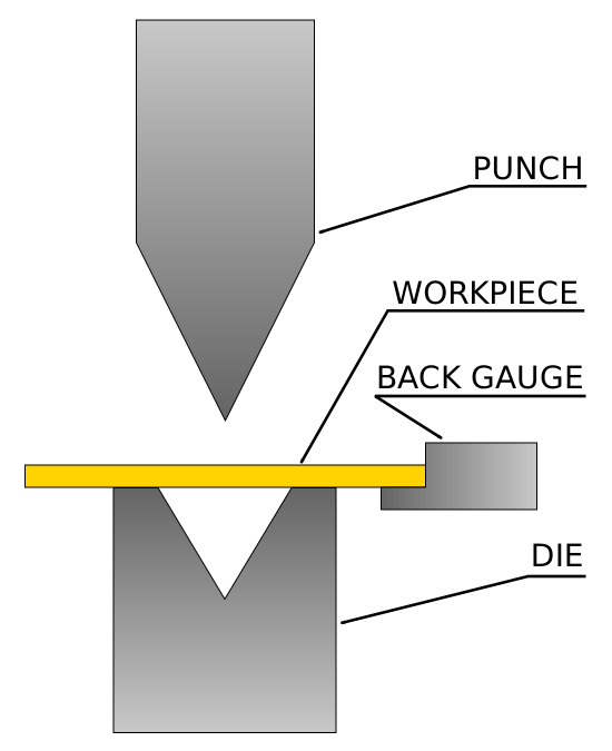
Image: Asurnipal, Wikimedia Commons, CC BY-SA 4.0.
It narrows the first tool and coupon trial. It is not a guarantee for every coil, finish or press brake.
Unless stated otherwise, bend-radius tables refer to the finished inside radius after unloading.
Calling out only "aluminum" or "stainless" is not enough to select a safe radius.
Cut the coupon in the intended grain direction and use the actual punch, die and process.
How should this sheet metal bend radius chart be used?
Use it to reject obviously unrealistic radii and choose a conservative first coupon. Do not release production from the chart alone. The same alloy can move from a tight bend to a crack-prone bend when its temper, thickness or bend-line orientation changes.
The FAA's aluminum reference, for example, does not publish one value for 6061. It separates temper and sheet thickness, and provides a band of recommended radii for a 90-degree bend. That structure is more useful than a generic claim such as "aluminum equals 1T." High-strength steel producers likewise tie guaranteed bendability to a named grade, thickness, direction and prescribed test conditions.
Specify the exact material designation, condition, thickness, inside radius, bend angle and critical bend-line direction. If any of those inputs are unknown, use a larger radius and schedule a controlled trial.
This guide separates three levels of information: published aluminum examples, broad planning bands for common materials, and production requirements that must come from a supplier data sheet or qualified shop bend table. That distinction prevents an online chart from being mistaken for a material specification.
What is minimum bend radius?
Minimum bend radius is the smallest inside radius that a specified sheet can be formed to under stated conditions without unacceptable cracking or other loss of integrity. When a sheet bends, material near the outside surface stretches while material near the inside surface compresses. A neutral layer between them changes length much less.
A tight radius concentrates outer-fiber strain. Lower ductility, a harder temper, greater thickness, rough cut edges and an unfavorable rolling direction can all reduce the margin before cracks initiate. That is why radius belongs to the material-and-process definition, not just the CAD model.
The letter t in a bend-radius chart means sheet thickness. A range of 1t to 2t means the recommended inside radius falls between one and two times the specified thickness under the chart's assumptions.
Sheet metal minimum bend radius chart by material
The most defensible online values are the ones attached to a named source and test condition. Start with the published aluminum table, then use the broader material chart only for early design screening.
| Aluminum alloy and temper | 0.032 in / 0.81 mm | 0.064 in / 1.63 mm | 0.128 in / 3.25 mm | Interpretation |
|---|---|---|---|---|
| 2024-O | 0 to 1t | 0 to 1t | 0 to 1t | Soft condition; strength after forming may require a controlled heat-treatment route. |
| 2024-T3 | 2 to 4t | 3 to 5t | 4 to 6t | Higher-strength temper; direction, edge quality and thickness become critical. |
| 5052-O | 0 | 0 to 1t | 0 to 1t | Very formable condition, but a zero entry is not permission to ignore tooling and surface damage. |
| 5052-H32 | 0 | 0.5 to 1t | 0.5 to 1.5t | Common formed-sheet choice; confirm exact gauge and mill condition. |
| 5052-H34 | 0 | 0.5 to 1.5t | 1.5 to 2.5t | Harder than H32, so the required band increases with thickness. |
| 6061-T4 | 0 to 1t | 0.5 to 1.5t | 1 to 2t | More formable than T6; final property requirements must match the temper route. |
| 6061-T6 | 0.5 to 1.5t | 1 to 2t | 1.5 to 3t | Do not replace this thickness-dependent range with a universal 3t or 6t rule. |
| 7075-O | 0 to 1t | 0 to 1t | 0.5 to 1.5t | Soft condition only; a later heat-treatment route requires engineering control. |
| 7075-T6 / T61 family | 3 to 5t | 4 to 6t | 5 to 7t | Crack-sensitive high-strength family; verify exact temper and specification before release. |
Adapted from FAA AC 43.13-1B, Table 4-6, recommended radii for 90-degree bends in aluminum alloys. Values are inside-radius bands expressed as multiples of thickness. Use the current applicable engineering data for regulated aircraft work.
| Material and condition | Early-design planning band | Primary risk | Required confirmation |
|---|---|---|---|
| Low-carbon steel, annealed or common cold-rolled sheet | 0.5 to 1t | Tight radius, burr direction, work hardening | Grade data, mill condition, actual V-die and shop bend table |
| 304 / 316 stainless, annealed | 1 to 2t | Work hardening, springback, surface galling | Grade, thickness, grain direction, finish protection and tooling |
| High-strength steel | Grade-specific; often 1t or higher | Cracking, large springback, excessive force | Producer's guaranteed R/t, punch radius, die opening and orientation |
| C110 copper, annealed | 0 to 1t | Surface marking, temper variation, electrical-conductor requirements | Temper, edge condition and supplier bend guidance |
| C260 brass, annealed to half-hard | 0.5 to 1.5t | Temper and grain sensitivity, stress cracking | Exact temper and bend direction; do not apply to free-machining brass |
| Commercially pure titanium Grade 2, annealed | 2 to 3t | Springback, galling, surface contamination | Material specification, temperature and tooling procedure |
| Ti-6Al-4V Grade 5 | 4 to 6t as a cold-forming screen | Low cold formability and crack initiation | Supplier-approved hot/cold forming route and inspection plan |
These are intentionally broad screening bands, not guaranteed minimums. A named product data sheet overrides this table. SSAB, for example, publishes guaranteed minimum inner radii for specific high-strength grades and thickness ranges rather than one value for all high-strength steel.
Many charts mix air-bend results, punch radii, finished radii, 90-degree coupon tests and informal shop rules. Before comparing numbers, confirm that both sources define the same radius, bend angle, thickness band, direction and material condition.
Minimum bend radius and bend allowance calculator
Select a material family, enter thickness and choose bend-line orientation. The tool converts the planning R/t band into a dimensional inside radius and calculates bend allowance using your K-factor.
Describe the bend
Use the exact material condition whenever it is known. The defaults are for explanation, not production release.
Calculator limitation: direction multipliers are conservative planning adjustments, not standard values. The FAA bands shown on this page assume a 90-degree aluminum bend; other materials and processes require supplier or shop data. Bend allowance uses BA = radians x (R + K x t).
Six factors that move the minimum radius
Composition changes ductility
Alloys within the same metal family can respond very differently. 5052-H32 and 6061-T6 are both aluminum, but their forming windows are not interchangeable.
Strength is not formability
Work-hardened or heat-treated conditions generally need more radius than annealed material. The drawing and purchase order must carry the temper, not only the alloy.
The range changes with gauge
Published tables often increase R/t as thickness rises. Multiplying one thin-sheet value across every gauge can understate the requirement.
Rolling texture is directional
Many sheets form more reliably when the bend line is transverse to the rolling direction. The material producer's definition takes priority over a generic rule.
Cracks start at stress raisers
Burrs, sheared-edge damage, notches and heat-affected cut edges can trigger cracking even when the nominal radius looks acceptable.
The press creates the real radius
Punch nose, V opening, bend method, tonnage, friction and springback determine the radius that exists after unloading.

How should bend direction and edge condition be specified?
The bend line is the axis of the bend. A bend line perpendicular to the rolling direction is commonly called bending across the grain; a parallel bend is with the grain. FAA guidance for aluminum recommends placing bend lines at an angle to the grain, preferably 90 degrees, where practicable.
That preference should not be turned into a universal percentage reduction. Modern high-strength products may carry guaranteed bendability in both directions, while another product may publish different longitudinal and transverse limits. Use the mill certificate and producer's bend table.
- Mark rolling direction before nesting blanks.
- Give the tightest and most critical bend the favorable orientation.
- Deburr the tensile-side edge and remove crack-starting notches.
- Keep bend reliefs and holes far enough from the bend zone.
- Use a coupon cut by the same laser, shear or punch process as production.
Air bending, bottoming and coining do not create the same radius
A material chart answers whether the sheet can tolerate a radius. A tooling chart answers what radius the machine will actually create. Both must agree.
Flexible, but process-dependent
The sheet contacts the punch and two die shoulders without fully matching the die walls. Penetration controls angle, and the achieved radius depends strongly on material behavior and V opening.
More tool contact
The workpiece is driven deeper toward the die geometry. Required tonnage and springback control differ from air bending, so do not reuse a K-factor or bend deduction without testing.
High force, tight imprint
High local pressure plastically sets the bend region. It can reduce springback but may impose a tighter effective radius and higher surface or tooling risk.
The die opening, punch nose and forming method determine the achieved inside radius. Use the machine/tooling supplier's calculator or bend guide to confirm force, minimum flange, die load and inner radius before running the part.
Minimum radius and bend allowance solve different problems
Minimum radius protects formability. Bend allowance predicts the length of material in the bend zone so the flat pattern reaches the required finished dimensions.
A is bend angle in radians, R is inside radius, K is the neutral-axis factor and t is material thickness.
For a 90-degree bend only. Use the actual achieved R and a validated shop K-factor or bend table.
SOLIDWORKS and Autodesk define K-factor as the neutral-axis location relative to thickness and use the same basic bend-allowance relationship. The formula is straightforward; selecting K is the difficult part. K is affected by material, radius-to-thickness ratio, tooling and forming method. A generic 0.33 can be useful for a rough model but should not replace a measured bend deduction when dimensional tolerance matters.
Worked example: for 1.5 mm sheet, a 2.25 mm inside radius, a 90-degree bend and K = 0.33, BA is approximately 4.31 mm. Change the real radius or K-factor and the flat length changes, even though the outside part dimensions remain the same.
What does a failed bend reveal?
Outer-fiber cracking
Likely contributors include a radius below the real material limit, hard temper, unfavorable direction, a damaged edge or a punch that creates a tighter radius than the drawing intended.
Excessive springback
Confirm material strength and thickness, bend method, actual radius and angle program. Do not solve springback by blindly reducing radius below the safe forming limit.
Orange peel
A coarse surface can reflect grain size and strain level. Increasing radius may reduce localized strain, but material selection and finish requirements also need review.
Wrinkling or flange distortion
Review unsupported flange geometry, bend method, blank restraint, die opening and thickness. Radius alone may not be the root cause.
Surface scratches or galling
Stainless and soft nonferrous sheet may mark on dirty or inappropriate tooling. Check tool finish, film, lubrication policy and surface-contact pressure.
Angle variation along the bend
Check material thickness tolerance, crown compensation, tool alignment, deflection and lot hardness before changing the CAD radius.
Use a five-step bend-coupon workflow
A coupon turns an internet planning range into shop-specific evidence. It should reproduce the material, direction, cut edge, tooling and bend method that production will use.
- Verify alloy, temper, thickness tolerance and rolling direction from traceable material documentation.
- Cut coupons in every critical orientation with the production blanking process.
- Start at or above the conservative end of the published radius band.
- Measure inside radius and final angle after unloading; record punch, die, force and program.
- Inspect the outer surface and edges at the magnification and acceptance level appropriate to the part.
Only after a coupon passes should the shop reduce radius or optimize the flat pattern. For structural, pressure, aerospace, fatigue-loaded or otherwise regulated parts, follow the governing specification and qualified inspection plan.

From material callout to production bend
Name the stock
Alloy, grade, temper, thickness, finish and applicable specification.
Choose orientation
Map rolling direction and protect the tightest bend during nesting.
Match tooling
Confirm punch, V opening, force, flange access and bend method.
Run coupons
Measure achieved radius, springback, surface and edge integrity.
Lock the table
Store approved bend deduction, K-factor and inspection evidence.
What should the sheet metal drawing and RFQ include?
Drawing essentials
- Inside bend radius and bend angle.
- Material alloy or grade, temper/condition and thickness.
- Rolling direction when it controls bendability.
- Critical flange, hole-to-bend and relief dimensions.
- Angular and linear tolerances after forming.
- Surface class and acceptable witness marks.
Supplier questions
- Which bend table and tooling family will be used?
- What inside radius will the selected V opening produce?
- Is the proposed radius guaranteed for this exact grade and thickness?
- How is grain direction controlled during nesting?
- What coupon and inspection evidence is available?
- Which bend deduction will drive the flat pattern?
Real sheet cannot form a zero-radius mathematical corner without a material- and process-specific hemming or coining operation. Dimension the intended inside radius and verify that adjacent holes, tabs and mating parts tolerate the resulting bend zone.
Continue from formed sheet to the joining process
Once the blank and bend are stable, the next constraint is often how formed panels are joined without unacceptable distortion, gap or surface damage.
Sheet metal bend radius FAQ
What is the minimum bend radius for sheet metal?
There is no universal value. The minimum inside radius depends on alloy, grade, temper, thickness, rolling direction, bend angle, edge quality and forming method. Use a material-specific chart and confirm it on the actual press-brake setup.
Is minimum bend radius measured inside or outside?
Most material bend-radius tables refer to the inside radius after the part is unloaded. Verify the source because punch radius, theoretical radius and outside radius are different values.
What does 1t bend radius mean?
It means the inside radius equals one material thickness. For 2 mm sheet, 1t is a 2 mm inside radius; 2t is 4 mm.
What is the minimum bend radius for 5052-H32 aluminum?
FAA Table 4-6 gives thickness-dependent bands. At approximately 0.064 in sheet it lists 0.5t to 1t; at 0.128 in it lists 0.5t to 1.5t. Confirm the exact gauge, direction and application requirements.
What is the minimum bend radius for 6061-T6 aluminum?
The FAA reference lists about 0.5t to 1.5t at 0.032 in, 1t to 2t at 0.064 in and 1.5t to 3t at 0.128 in. This demonstrates why one universal 6061-T6 number is misleading.
Should the bend run with or across the grain?
Across the rolling direction is often preferred for tighter bending, but the material producer's rules control. Some modern grades have guaranteed values in both directions; others require different radii.
Does a wider V-die increase inside radius?
In air bending, V opening strongly influences the naturally formed radius. The exact relationship varies with material and tool system, so use the press-brake or tooling supplier's calculation rather than a universal percentage.
Is punch radius the same as finished inside radius?
Not necessarily. In air bending the sheet may not fully conform to the punch nose, and springback changes the unloaded geometry. Measure the finished coupon.
Can hardened sheet be bent to the annealed radius?
Usually that assumption is unsafe. Harder or heat-treated conditions commonly need a larger radius and produce more springback. Use the exact temper's data and consider a controlled form-then-heat-treat route only when the material specification permits it.
How is bend allowance calculated?
A common relationship is BA = angle in radians x (inside radius + K-factor x thickness). Use the achieved radius and a validated K-factor or shop bend table for accurate flat patterns.
Is K-factor always 0.33?
No. K-factor represents the neutral-axis location and changes with material, R/t, tooling and bend method. A value such as 0.33 is only a preliminary assumption unless validated against measured parts.
Why does a bend crack even when the chart says it should work?
Possible causes include a harder lot, wrong rolling direction, burrs or cut-edge damage, an achieved radius smaller than specified, incorrect material identification or a chart with different assumptions.
How should minimum bend radius be shown on a drawing?
Dimension the inside radius and angle, name the material and condition, and specify rolling direction when critical. Add finished tolerances and surface requirements rather than leaving the shop to infer them.
Can this calculator replace a bend test?
No. It converts planning R/t bands and explains bend allowance. Production release still requires supplier data, the actual tooling setup and an inspected coupon or qualified process.
Sources used for this guide
- FAA AC 43.13-1B, Change 1: bending-metal guidance and recommended radii for 90-degree aluminum bends.
- SSAB press-brake recommendations: grade-specific minimum radius, punch radius and rolling-direction considerations.
- SSAB Strenx 700MC Plus data: example of thickness-dependent guaranteed minimum radius for a named high-strength steel.
- TRUMPF bending methods: distinction between air bending and other press-brake processes.
- TRUMPF BendGuide: tooling, die width, press force and inner-radius planning.
- SOLIDWORKS K-factor documentation: neutral-axis definition and bend-allowance equation.
- Autodesk Inventor sheet-metal unfold reference: K-factor, bend-table and unfolding methods.
- OSHA powered press-brake safety: point-of-operation and material-handling hazards.
Planning a formed sheet-metal assembly?
Send the alloy, temper, thickness, drawing, bend direction, joint geometry and target finish. Oceanplayer can help evaluate the laser-welding stage after the bending process has been defined.