


Laser welding engineering guide
What Is Deep Penetration Welding—and How Does a Keyhole Form?
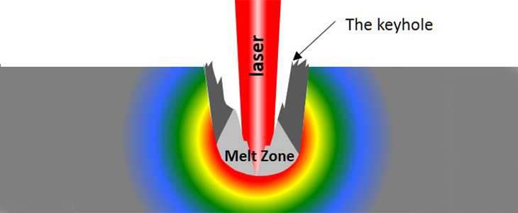
Deep penetration welding is a high-energy-density fusion process in which localized melting and vaporization create a deep vapor depression, commonly called a keyhole. The focused beam couples energy along the cavity walls; as the heat source travels, molten metal flows around the cavity and solidifies into a narrow, high-aspect-ratio weld.
Image: Pipimaru / Wikimedia Commons, CC BY-SA 3.0.
Quick answer
The keyhole is useful only when it stays stable.
High power density can open a vapor cavity, but a qualified weld also depends on travel speed, spot size, focus, beam profile, material absorptance, fit-up and shielding. Power alone does not prove penetration or quality.
Metal evaporation creates recoil pressure that pushes the liquid surface downward.
Multiple reflections inside a deep depression can raise the fraction of incident laser energy absorbed.
The moving cavity transports energy below the original surface and leaves a deep weld behind it.
An unstable cavity can close around vapor or shielding gas before it escapes.
Definition and scope
What does deep penetration welding actually mean?
The term describes a weld mode, not one specific machine. Laser beam welding and electron beam welding are the best-known keyhole processes; plasma keyhole and some high-energy arc variants use different physics and operating windows.
In laser welding, TWI distinguishes conduction-limited welding from keyhole welding by the power density delivered to the workpiece. Conduction mode melts primarily at the surface, so the fusion zone is relatively wide and shallow. At sufficiently high focused intensity, metal vaporization creates a cavity filled with vapor or plasma. The beam then interacts with the cavity rather than only with a flat surface.
The widely quoted range of approximately 106–107 W/cm² is a useful laser-welding reference, not a universal switch for every material, wavelength and beam shape. NIST measurements show that conduction, transition and keyhole behavior can overlap dynamically, and that absorptance changes with the evolving cavity geometry.
Heat does not simply “travel downward instead of sideways.” The beam deposits energy at and within the vapor depression while conduction, convection, vapor recoil, surface tension and fluid flow act together. A deep weld is the macroscopic result of that coupled process.
Mode comparison
Conduction welding and keyhole welding create different fusion geometry.
| Decision factor | Conduction-limited laser welding | Deep penetration / keyhole welding | Engineering implication |
|---|---|---|---|
| Primary interaction | Surface absorption followed by heat conduction into the workpiece. | Melting plus vaporization creates a deep vapor depression. | Do not assume the same power-speed logic transfers between modes. |
| Typical focused intensity reference | Often below about 105 W/cm². | Often above about 106 W/cm²; the transition depends on the system and material. | Use measured spot size and beam quality, not nominal source power alone. |
| Fusion-zone shape | Relatively wide and shallow. | Relatively narrow and deep, frequently with a wine-glass or nail-head profile. | Cross-section the actual joint before declaring a qualified mode. |
| Absorptance | Strongly influenced by wavelength, surface condition and temperature. | Multiple internal reflections can substantially increase energy coupling. | Absorptance is dynamic; a constant efficiency preset is only a planning assumption. |
| Main benefit | Smooth, controlled melting for thin or appearance-sensitive joints. | Greater depth per pass and a smaller molten volume than many multi-pass alternatives. | Compare complete cycle time, distortion and inspection—not penetration alone. |
| Main process risk | Insufficient fusion if energy delivery is too low. | Porosity, spatter, underfill or root instability when the keyhole is unstable. | There is both a lower and an upper useful process boundary. |
The power-density values are common laser-welding references reported by TWI. They are not universal acceptance criteria or guaranteed production thresholds.
Interactive planning aid
Estimate incident power density before planning a keyhole trial.
This calculator uses a circular top-hat spot approximation. Real Gaussian or multimode beams have different peak intensity distributions, so the result is a screening value—not proof of keyhole formation.
Enter nominal laser conditions
Plan a controlled keyhole trial
The nominal incident intensity is above the common laser keyhole reference. Confirm actual spot size, focus position, penetration and pore behavior on production-representative coupons.
Check edge preparation, root support, focal position, shielding and the required full- or partial-penetration profile. The calculator does not predict penetration depth.
Formation sequence
How does a laser-welding keyhole form?
A keyhole is not a mechanically drilled hole. It is a transient vapor depression surrounded by moving liquid metal. NIST describes a feedback loop in which heating changes absorption, vaporization generates recoil, the surface depresses and the cavity redirects more reflected light into the metal.
The focused beam heats the surface. Absorptance changes with wavelength, finish, temperature, oxide and phase.
The surface becomes a melt pool governed by conduction, convection, surface tension and beam-driven forces.
Evaporating atoms carry momentum away; the reaction force pushes down on the liquid surface.
As the depression deepens, incident light can reflect onto other cavity walls instead of escaping immediately.
Liquid flows around the moving cavity and solidifies. Stable motion produces a consistent root; unstable motion can trap gas or create irregular penetration.
Dynamic equilibrium
What keeps the keyhole open—and what makes it collapse?
A useful keyhole exists only while downward and opening forces remain compatible with the forces and flows that tend to close or reshape the cavity.
Vapor recoil
Evaporation produces recoil momentum that depresses the liquid surface.
Surface tension
The molten metal tends to minimize surface area and close the cavity.
Hydrodynamics
Marangoni flow, buoyancy, vapor jets and travel motion redistribute the melt.
Beam and gas
Power, focus, speed, beam motion and shielding change cavity geometry and plume behavior.
This is a conceptual balance, not a WPS equation. Real keyholes oscillate. A process can be penetrative yet unstable, and an attractive top bead can hide root porosity or incomplete fusion.
Parameter interactions
Which variables control penetration depth and keyhole stability?
Delivered power
Power sets the available energy rate, but it must be evaluated with spot size, beam shape and optical losses.
Spot size and focus
Reducing diameter increases nominal intensity rapidly. Defocus can widen the bead while reducing penetration.
Travel speed
Speed changes interaction time and line energy. Too slow can enlarge the pool; too fast can lose root continuity or promote humping.
Beam profile
Single-mode, multimode, ring-core and oscillated beams distribute intensity differently even at the same total power.
Material coupling
Wavelength, reflectivity, conductivity, surface finish and phase transformation affect how energy enters the workpiece.
Joint fit-up
A narrow beam demands reliable seam position, edge condition and gap. Filler or hybrid welding may increase tolerance.
Shielding and plume control
Gas type, direction and flow influence oxidation, plume interaction and porosity without replacing surface preparation.
Beam oscillation
Wobble can alter pool width, mixing and gap bridging, but it also changes effective intensity and interaction pattern.
Penetration objective
Full penetration, partial penetration and controlled melt-through require different root support and acceptance evidence.
Two machines can calculate the same nominal W/cm² while producing different results because focal quality, beam parameter product, temporal stability, actual delivered power and material absorptance differ.
Process selection
Laser, electron beam, plasma keyhole or hybrid welding?
All four can produce narrow, penetrative welds, but they solve different production constraints. Avoid choosing from a universal “maximum thickness” chart; usable depth depends on equipment, alloy, joint and qualification evidence.
Laser beam welding
Focused optical energy in atmosphere or controlled shielding, commonly integrated with CNC or robotic motion.
- Strong fit for repeatable production and low-distortion joints.
- Demands beam safety, precise focus, seam position and fit-up.
- Can be autogenous, wire-assisted or hybridized with an arc.
Electron beam welding
A focused electron beam supplies very high energy density, commonly within a vacuum chamber.
- Excellent access to very high aspect ratios and reactive materials.
- Vacuum size, pump-down, part handling and radiation shielding shape the cycle.
- Part geometry must fit the chamber and beam access strategy.
Keyhole plasma arc welding
A constricted arc can open a through-keyhole in an appropriate thickness and parameter window.
- Uses arc-welding architecture rather than a focused optical beam.
- Often more tolerant of some surface and joint conditions than autogenous laser welding.
- Depth, speed and joint options differ from laser and EBW.
Hybrid laser-arc welding
A laser keyhole and an arc act in a shared pool, combining deep energy delivery with filler and arc-assisted gap bridging.
- Useful where chemistry, reinforcement or fit-up needs filler metal.
- More variables must be synchronized and qualified.
- Fixture, torch-beam geometry and consumables become critical.
Troubleshooting
What defects signal an unstable keyhole?
Treat the visible symptom as evidence, not as a one-parameter diagnosis. TWI notes that laser-weld porosity can come from contamination, inadequate shielding or keyhole instability and collapse.
Gas becomes trapped during closure
Review surface cleanliness, shielding delivery, joint moisture, partial-penetration geometry and the stability of power, focus and speed. Confirm with cross-section or qualified NDT rather than the cap alone.
The cavity oscillates or intermittently closes
Check delivered power, focal location, spot condition, seam tracking, travel motion, reflective return, plume interaction and changes in joint gap.
Energy or fluid flow is too aggressive
Very high local intensity, unsuitable focus, abrupt starts, poor shielding or an oversized pool can eject metal. Review ramps, intensity distribution and speed together.
Molten metal cannot level behind the cavity
Travel speed, pool length, surface tension and backward melt flow interact. A slower speed, modified focus or controlled beam motion may help, but must be retested.
Full penetration lacks support or control
Check gap, backing, focal position, speed, power ramp and the target root reinforcement. Thin or poorly fitted joints can move suddenly from penetration to excessive melt-through.
Metallurgy—not only keyhole physics—controls failure
Alloy composition, restraint, fusion-zone shape, filler selection and cooling rate can dominate. A stable cavity does not guarantee crack-resistant metallurgy.
Verification
How do you prove penetration instead of assuming it?
A shiny cap is not proof of full penetration, root continuity or low internal porosity. The inspection plan must follow the product code, customer specification, joint geometry and defect sensitivity.
Cut, prepare and etch a transverse coupon to reveal fusion-zone depth, root shape and aspect ratio. This is the most direct procedure-development evidence.
Assess cap, underfill, undercut, melt-through and surface-breaking discontinuities where access allows.
Useful for volumetric discontinuities in suitable geometry, but the applicable technique and acceptance criteria must be specified.
Conventional or phased-array UT can support production inspection where geometry, procedure and qualification make it suitable.
Back reflection, optical emission, acoustic signals or coherent imaging can indicate process changes only after correlation with destructive and NDT evidence.

Standards map
Choose the acceptance system before developing the parameter window.
| Document | What it addresses | Important limitation |
|---|---|---|
| ISO 13919-1:2019 | Quality levels for imperfections in electron- and laser-beam welded joints in steel, nickel, titanium and their alloys. | The quality levels describe production quality, not fitness for purpose; NDT methods may require supplementary requirements. |
| ISO 13919-2:2021 | Quality-level guidance for electron- and laser-beam welded aluminum, magnesium, their alloys and pure copper. | Metallurgical effects and detailed NDT sizing methods are outside its scope. |
| AWS D17.1/D17.1M:2024 | Fusion-welding requirements for aerospace hardware, including high-energy beam processes. | Applies when invoked by contract documents and includes design, qualification, fabrication, inspection and acceptance provisions. |
| ASME BPVC Section IX | Qualification of welding, brazing and fusing procedures and personnel for applications governed by ASME construction codes. | Section IX qualification must be used with the applicable construction code and customer requirements. |
Always confirm the edition and contractual hierarchy before quoting, qualifying or accepting production. A generic blog chart cannot replace the applicable code.
Material and joint behavior
The same calculated intensity does not create the same keyhole in every metal.
Review hardenability, coating, scale, root condition and whether high cooling rate creates brittle HAZ or weld metal.
Protect the surface and root as required; evaluate porosity, ferrite balance, sensitization risk and distortion criteria.
Oxide, hydrogen, reflectivity and thermal conductivity complicate initiation and pore control. Surface preparation is critical.
High conductivity and wavelength-dependent absorptance can make process initiation sensitive. Use actual alloy and surface state.
Shielding purity, contamination, cracking response and service-specific metallurgy can govern the procedure more than bead shape.


Allowable gap depends on beam diameter, thickness, joint type, full- or partial-penetration objective, filler strategy, fixture stiffness and acceptance criteria. A single percentage cannot represent every keyhole weld.
Procedure development
A practical five-step keyhole welding trial.
Document alloy, thickness, joint drawing, penetration objective, root profile, mechanical requirements, code and cycle target.
Measure or verify power at the workpiece, spot size, focus position, beam profile, speed, shielding and motion repeatability.
Vary one controlled parameter at a time around a reasoned starting point; record starts, stops and transitional behavior.
Use macro sections plus the NDT and mechanical tests required by the application. Record defects as well as the best-looking sample.
Challenge realistic gap, part variation, focus drift and speed tolerance before freezing the WPS and production control plan.
Continue engineering
Related laser-welding resources
Frequently asked questions
Deep penetration and keyhole welding FAQ
What is deep penetration welding?
Deep penetration welding is a fusion mode in which a concentrated energy source creates a deep vapor depression or keyhole. Energy couples along the cavity and the moving molten pool solidifies into a relatively narrow, deep fusion zone.
How is a keyhole formed in laser welding?
The focused beam heats, melts and vaporizes metal. Vapor recoil depresses the liquid surface. As the depression deepens, internal reflections can increase absorption, reinforcing the cavity while the beam moves along the joint.
What power density is needed for keyhole welding?
TWI commonly places laser keyhole welding above approximately 106–107 W/cm² and conduction-limited welding below roughly 105 W/cm². The actual transition depends on wavelength, material, surface, beam profile, spot size and travel conditions.
Is a high-power laser automatically a deep-penetration welder?
No. Power must be focused into an appropriate spot and delivered stably at the joint. A defocused high-power beam can remain shallow, while a well-focused lower-power beam may reach keyhole intensity in a smaller spot.
What is the difference between conduction and keyhole welding?
Conduction mode primarily heats and melts from the surface, producing a relatively wide, shallow weld. Keyhole mode adds vaporization and a deep cavity, producing a higher depth-to-width fusion profile.
Why does a keyhole increase laser absorption?
A deep depression redirects some light onto other cavity walls instead of allowing it to reflect away. NIST measurements have shown that absorptance can rise strongly as vapor-depression depth and geometry develop.
What causes porosity in keyhole laser welds?
Potential causes include contamination, hydrogen sources, inadequate shielding and an unstable or collapsing keyhole that traps vapor or gas. Diagnosis requires cross-section or suitable NDT, not just visual inspection of the cap.
Can deep penetration welding eliminate filler wire?
Some close-fitting laser or electron-beam butt joints can be welded autogenously. Filler is still needed when chemistry, reinforcement, joint gap, mechanical properties or the governing procedure require it.
Does keyhole welding always reduce distortion?
A concentrated process can reduce total molten volume and heat affected width compared with many multi-pass alternatives, but distortion still depends on restraint, joint sequence, line energy, geometry and phase transformation.
How can full penetration be verified?
Procedure development normally uses transverse macro sections to reveal the fusion profile. Production may add visual examination, radiography, ultrasonic testing or qualified inline monitoring according to the applicable specification.
Which standard covers laser-weld imperfections?
ISO 13919-1 covers quality levels for steel, nickel, titanium and their alloys; ISO 13919-2 covers aluminum, magnesium, their alloys and pure copper. Product codes and customer specifications determine the required level and inspection.
Is handheld laser welding the same as industrial deep-penetration laser welding?
Handheld systems can operate in a penetrative regime, but their beam motion, power, safety architecture, joint control and qualification context differ from fixed automated cells. Validate the actual tool, joint and acceptance criteria.
Can the calculator on this page predict penetration depth?
No. It calculates nominal incident intensity, gross line energy and spot area under simplified assumptions. Penetration must be established by representative welding trials and inspection.
Technical references
Sources used for this guide
- TWI — What is laser welding and how does it work?
- NIST — Simultaneous measurements of keyhole depth and absolute absorptance.
- NIST — Measuring dynamic light absorption during laser welding.
- TWI — Typical defects in laser welds.
- ISO 13919-1:2019 — Electron- and laser-beam welded joints, Part 1.
- ISO 13919-2:2021 — Electron- and laser-beam welded joints, Part 2.
- AWS D17.1/D17.1M:2024 — Fusion welding for aerospace applications.
- ASME BPVC Section IX — Welding, brazing and fusing qualifications.
The article provides engineering orientation, not a qualified welding procedure or acceptance decision. Use the edition and requirements invoked by the final contract.
From theory to a qualified coupon
Find a stable penetration window for your actual joint.
Send Oceanplayer the alloy, thickness, joint drawing, gap range, penetration target, weld length and acceptance standard. We can organize a representative sample-test path and recommend a practical machine configuration.