oceanplayer

Oceanplayer Industrial Laser Equipment | Cleaning, Welding, Marking, Automation Sample Testing | Free Engineering Tools | Global Shipping
Main Systems
Best Seller Oceanplayer 500W pulsed laser cleaning machine
Featured Model
500W Pulsed Laser Cleaner

Higher pulse cleaning speed with controlled surface impact.

500W PulsedFine ControlBest Seller
Engineering Tools
Applications
Industries
Company
Resources
Weld Pool Dynamics & Process Engineering

4 Forces That Shape Every Weld Pool

Marangoni flow, electromagnetic force, buoyancy and heat-source loading provide a practical map for reading many weld pools. This guide explains what each mechanism can—and cannot—tell you, then connects the arc-welding model to laser conduction and keyhole welding.

Arc vs LaserEvidence Before AdjustmentUpdated August 2026
Visible molten weld pool during shielded metal arc welding
The pool is a coupled fluid, thermal and solidification system.A useful diagnosis begins by identifying the welding process, material heat, joint, position and observed behavior—not by assigning one force from appearance alone.Image: Jose Bueno, CC BY 3.0, via Wikimedia Commons.
Surface driver

Marangoni convection

A temperature- and chemistry-dependent surface-tension gradient produces tangential stress, redistributing heat and molten metal across the pool.

Current-driven body force

Lorentz force

In current-carrying arc pools, current density interacting with its magnetic field creates a J × B force that can drive inward and downward circulation.

Density and orientation

Buoyancy and gravity

Density differences move hotter and cooler liquid, while gravity and weld position influence sagging, free-surface shape and large-pool behavior.

Heat-source loading

Plasma shear or laser recoil

Arc plasma can shear and depress a pool; a laser keyhole is instead sustained largely by vapor recoil balanced against capillary and hydrostatic forces.

Quick Answer

What forces shape a weld pool?

Four mechanisms offer a useful starting framework for many arc-welding pools: Marangoni surface-tension flow, electromagnetic or Lorentz force, buoyancy, and arc-plasma loading. Together they help explain why a pool spreads, deepens, trails, oscillates or becomes unstable. They do not form a universal ranking, and the fourth category must be defined carefully: tangential plasma shear and normal arc pressure act differently.

The balance changes with process, current distribution, arc length, electrode geometry, material chemistry, shielding gas, joint fit-up, travel direction, position, filler transfer and pool size. GMAW and FCAW add droplet impact. Submerged arc welding adds flux and slag interactions. Laser keyhole welding requires a different force map in which vaporization-induced recoil pressure, capillary pressure, vapor shear and multiple optical reflections are central; Lorentz force is not inherently present when no welding current flows through the pool.

Therefore, weld-pool appearance is evidence—not a diagnosis. Use it to decide what to check: recorded current or laser power, arc length or focus, travel speed, gas delivery, surface condition, material heat, fit-up, monitoring data and a representative cross-section. Parameter changes must remain inside the approved WPS or qualified laser process window.

Start With the Physical System

A weld pool is not the same as the entire weldment.

The molten pool exists only while the local temperature exceeds the liquidus. It is bordered by the fusion boundary and followed by solidifying weld metal. The heat-affected zone is heated but not melted, so it should not be described as part of the pool.

Flow carries heat before the metal freezes.

This is why nominal power or current alone cannot predict penetration. Energy must first reach the workpiece, then be absorbed, transported through the molten metal and finally released as the pool solidifies.

Three connected questions

How is energy deposited? An arc distributes electrical and plasma heat over an anode region. A laser delivers irradiance through a focused beam whose absorption may change sharply when a keyhole forms. The same input power can create different power density, footprint and coupling.

How does liquid metal move? Surface stress, electromagnetic body force, density gradients, external pressure, shear, gravity and—where applicable—droplet impact or vapor recoil create circulation. That circulation moves heat far faster than conduction alone in many operating regimes.

How does the pool solidify? The moving heat source leaves a trailing liquid region that feeds shrinkage and transforms into a weld bead. Pool length, tail shape, grain growth, segregation, restraint and crater termination affect crack risk.

Important qualification

The title uses “four forces” as an accessible teaching model. A complete multiphysics model can also include capillary pressure, hydrostatic pressure, droplet momentum, vapor shear, recoil pressure, deformation and phase-change terms. Which terms matter is a property of the specific process—not a fixed amperage threshold.

Fusion zone, partially melted zone and HAZ

The fusion zone is the material that melted and resolidified. Some alloys can exhibit a partially melted zone immediately outside the fusion boundary, but its extent and significance are alloy- and process-dependent. The HAZ remained solid while experiencing a thermal cycle that may change grain structure, hardness, phase balance or corrosion response. None of these regions should be assigned a universal width without the alloy, section, heat source and procedure.

Comparison Table

The four-force map—without false thresholds.

No universal rule says one mechanism “takes over” at 200, 250 or 300 amperes. The useful question is which mechanism becomes more influential after the actual geometry, current distribution, material and process are defined.

MechanismWhere it actsPhysical originTypical influenceKey caveat
Marangoni convectionFree surfaceSpatial gradient of surface tension caused by temperature and compositionCan drive outward or inward surface flow, altering width, penetration and wettingDirection is alloy- and chemistry-dependent; there is no universal sulfur switch point
Lorentz / electromagneticLiquid volume carrying currentCurrent density interacting with magnetic field, expressed as J × BOften promotes inward/downward circulation in simplified axisymmetric GTAW modelsDepends on current path, electrode, arc root and pool geometry; not inherent to ordinary laser welding
Buoyancy and gravityLiquid volume and free surfaceDensity change with temperature plus gravitational accelerationHotter, lower-density liquid tends to rise; position affects sag and pool supportOften modest in small flat pools, yet relevant for large pools, position and unusual gravity
Plasma shear / source pressurePool surfaceGas momentum creates tangential shear; stagnation pressure acts normallyCan push liquid outward/backward, depress the surface or contribute to humpingShear and pressure are separate tractions and respond to torch, gas and arc geometry
Laser recoil pressureKeyhole wallMetal vaporization produces a normal reaction pressureOpens and sustains the keyhole, changes absorption and can drive strong recirculationCentral to keyhole laser welding, but not the same as arc pressure
Interactive Force Explorer

See what each mechanism contributes.

Select a force to review its physical origin, common visual consequence and the evidence needed before changing a procedure.

Surface-tension gradient

Marangoni convection

Temperature and dissolved surface-active elements change surface tension across the pool. That gradient pulls the surface liquid and redistributes heat, which can change pool width, depth and toe wetting.

First evidenceMaterial heat, surface condition, shielding chemistry and a macro cross-section.
Do not assumeA universal sulfur threshold or guaranteed direction for every alloy and process.
Force 1

Marangoni flow begins at the surface.

It is not “surface tension pushing down.” It is tangential stress created because surface tension differs from one point to another.

Why the direction can reverse

For many clean liquid metals, surface tension decreases as temperature rises. The hot center then has lower surface tension than the cooler rim, so surface liquid tends to flow outward. Heat is carried toward the sides, often favoring a wider and shallower pool. Soluble surface-active elements—including sulfur, oxygen and selenium in some steels—can modify the surface-tension-versus-temperature relationship. Under particular conditions the surface flow can turn inward and carry heat toward the pool center and downward.

This mechanism explains why two material heats can respond differently under nominally identical autogenous GTAW settings. It does not justify a universal rule such as “below 30 ppm is outward and above 60 ppm is inward.” The transition depends on alloy composition, soluble rather than total surface-active content, deoxidizers, oxygen potential, temperature field and heat-source conditions. Research by Mills and Keene and later process models supports the mechanism while emphasizing variability.

What a material certificate can—and cannot—tell you

An MTR or CMTR can identify the heat and report specified chemistry, which makes it valuable when penetration or bead shape changes after a supplier or heat change. Yet reported sulfur alone may not capture oxygen, surface films, trace elements or soluble state. Treat chemistry as a diagnostic clue; confirm the effect with a representative weld coupon and cross-section.

Better troubleshooting language

Instead of saying “sulfur caused shallow penetration,” say: “The new material heat coincided with a wider, shallower autogenous pool. Review heat chemistry and surface condition, verify the qualified equipment variables, then compare macrosections made within the approved procedure window.”

Active-flux TIG is not a one-mechanism shortcut

Active-flux TIG can increase penetration in qualified applications, but attributing every result solely to Marangoni reversal is too simple. Arc constriction and plasma behavior may also contribute. Flux chemistry, coating thickness, alloy, joint, root protection and acceptance requirements must be controlled through a qualified procedure rather than a generic promise of “double penetration.”

Force 2

Lorentz force follows the current path.

Electromagnetic force is a body force inside current-carrying liquid metal. It cannot be ranked from amperage alone because its direction and concentration depend on how current enters, spreads and exits the pool.

TIG welding arc acting above a molten weld pool

Arc geometry defines more than heat.

Electrode condition, arc length, gas, polarity and work-return path influence current density and plasma loading.

Photo: Mak04, public domain, via Wikimedia Commons.

The compact equation: J × B

Current density J interacting with magnetic field B produces a volumetric force. In simplified axisymmetric GTAW calculations, the pattern often drives liquid inward near the surface and downward beneath the arc, contributing to deeper heat transport. Real welds depart from the ideal model when the arc root moves, the pool becomes asymmetric, the work-return path creates arc blow, filler enters or joint geometry redistributes current.

Why “Lorentz dominates above 250 A” is unreliable

Electromagnetic influence usually grows strongly with current when other conditions remain similar, and some derivations show current-squared scaling under restrictive assumptions. But geometry and current distribution do not remain fixed across machines, electrodes and transfer modes. A threshold without electrode diameter, arc length, polarity, gas, joint, pool dimensions and validation evidence is not transferable.

Laser-welding boundary

A conventional fiber-laser beam does not drive welding current through the pool, so the arc-welding Lorentz term should not be copied into a laser model. Magnetic fields or hybrid laser-arc configurations can introduce electromagnetic effects, but those are special process definitions, not the default.

Forces 3 and 4

Gravity, buoyancy and heat-source loading reshape the surface.

These mechanisms become easier to understand when separated by direction: buoyancy acts through the volume, gravity loads the liquid mass, plasma shear acts tangentially and arc pressure acts normally.

Diagram showing circulation and heat flow inside a weld pool

Buoyancy is a density-driven body force.

Hotter liquid usually becomes less dense and tends to rise. Its relative importance changes with pool size, orientation and the other flow drivers.

Diagram: Lawrence Livermore National Laboratory / U.S. Department of Energy, public domain.
GMAW weld area showing molten pool and solidified weld metal

Consumable-electrode processes add droplet momentum.

Arc pressure and plasma shear act at the surface, while droplets can transfer heat and momentum directly into the liquid.

Diagram: Spangineer, CC BY-SA 3.0, via Wikimedia Commons.

Buoyancy and gravity

Buoyancy frequently appears weaker than surface-tension or electromagnetic flow in small, flat GTAW pools, yet “weaker” does not mean irrelevant. It can alter circulation and aspect ratio, and gravity becomes operationally obvious when a large molten volume is welded vertically or overhead. Sagging, root support, bead placement and travel technique then depend on the entire force balance.

Do not solve an out-of-position problem by increasing travel speed or reducing power blindly. Verify the qualified position, joint support, deposition rate, transfer mode, torch orientation and parameter window.

Plasma shear versus arc pressure

High-velocity plasma and shielding gas can exert tangential shear that drags surface liquid outward or backward. Normal stagnation pressure can depress the pool beneath the arc. They are related to the same heat-source environment but are not interchangeable. Their magnitude changes with current density, electrode tip, arc length, gas and constriction.

In high-speed arc welding, shear and rearward liquid transport can contribute to an elongated depression, undercut or humping. The correct response is evidence-driven: confirm actual speed, torch geometry, arc stability, transfer and WPS limits before changing a single variable.

The Laser-Welding Exception

A keyhole is held open by recoil pressure.

Oceanplayer customers often use fiber-laser systems, so the classic arc-force model needs a deliberate translation. Laser conduction mode and keyhole mode are different energy-coupling regimes.

Laser conduction mode

Power density is below the sustained keyhole regime. The surface melts, and heat flows downward mainly through conduction and liquid convection. Surface-tension gradients, buoyancy, gravity, beam shape and travel govern the resulting shallow-to-moderate pool.

  • Common strengthsSmooth appearance, controlled heat input and lower keyhole-instability risk.
  • Typical limitationsLower depth-to-width ratio and sensitivity to reflectivity, spot size and heat sinking.
  • Evidence to recordPower at the work, focus reference, spot/profile, speed, wobble, surface condition and cross-section.

Laser keyhole mode

Intense heating vaporizes metal. The reaction to vapor leaving the surface creates recoil pressure that opens a cavity. Multiple reflections inside the cavity can increase absorption, enabling deep penetration. Surface tension and hydrostatic pressure resist collapse while vapor and liquid flow continually reshape the keyhole.

  • Common strengthsHigh aspect-ratio penetration and fast travel with localized heat input.
  • Typical risksKeyhole oscillation, collapse, spatter, underfill and trapped pores when the balance becomes unstable.
  • Evidence to recordDelivered power, focus/spot, speed, wobble, gap, plume/video, shielding and macro or CT evidence.
Industrial laser welding of a metal pipeline

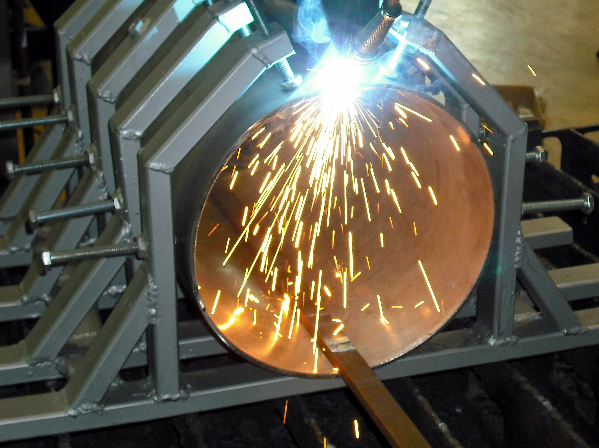
High power is only one part of the process.

Focus, beam profile, travel, gap, joint geometry, absorptance, shielding and plume control determine whether delivered power forms a stable pool.

Photo: Barbara Nasiłowska, CC BY 4.0, via Wikimedia Commons.

Why absorption changes dynamically

NIST measurements show that laser absorptance can evolve as a keyhole develops. That means a process may not respond linearly to a small change in focus, power or speed. Crossing from conduction toward keyhole behavior changes geometry, internal reflections and vaporization, which in turn changes how energy couples into the part.

What instability can look like

A wandering plume, intermittent spatter, a fluctuating penetration line or pores in cross-section can be consistent with an unstable keyhole, but none is proof by itself. The same visible symptom can result from contamination, gap, focus drift, protective-window damage, shielding disturbance or joint tracking. A process review must separate optical delivery, mechanical fit-up, material condition and thermal response.

Practical rule for laser buyers

Ask for a representative sample test with the real alloy, thickness, joint, finish and fit-up. A generic “1500 W penetrates X millimeters” chart cannot replace the qualified parameter window and acceptance evidence.

Process-Specific Priorities

The same symptom can come from a different mechanism.

A force map becomes useful only after the process is named. The table below ranks investigation priorities—not universal dominance or parameter settings.

ProcessImportant flow or loading termsHigh-value checksDo not transfer blindly
GTAWMarangoni, Lorentz, buoyancy, arc pressure and plasma shearElectrode geometry, arc length, polarity, material heat, gas, travel and macrosectionA sulfur or current threshold from another alloy or torch setup
GMAW / FCAWAll arc terms plus droplet heat and momentum, transfer-mode effectsWire feed/current, voltage, CTWD, transfer, torch angle, gas and joint fit-upA one-variable “add voltage” remedy for wetting or profile
SAWElectromagnetic flow, arc pressure, droplet impact, flux/slag interactionWire configuration, polarity, travel, bead aspect, flux condition and crater controlA pool-shape limit without the alloy, bead geometry and procedure
Laser conductionMarangoni, buoyancy/gravity, capillary effects and beam-driven thermal fieldDelivered power, spot/profile, focus reference, speed, wobble and surfaceArc-current force rankings
Laser keyholeRecoil pressure, capillary/hydrostatic pressure, vapor shear and liquid convectionPower density, keyhole stability, focus, gap, contamination, shielding and macro/CTA simple power-versus-thickness chart as proof of quality
Power, Speed & Geometry

Energy input changes the pool—but never alone.

The useful objective is a stable absorbed-energy window that creates required fusion without unacceptable distortion, defects or microstructural damage.

Arc energy is not automatically net heat input

The familiar voltage × current ÷ travel-speed expression describes electrical energy per unit length when units are handled correctly. Some codes or engineering methods apply process-efficiency factors to estimate net heat delivered. Those factors are context-specific, so use the governing code, procedure and measurement method. Do not silently combine “arc energy,” “heat input” and “absorbed energy” as if they were identical.

Laser power needs power density and coupling context

Average power without spot size, beam profile, focus location and travel speed cannot describe irradiance or energy per length. Wobble changes the effective footprint and dwell distribution. Reflective alloys and surface films affect coupling. Once a keyhole forms, absorption can increase through multiple reflections. Two systems both labeled 1500 W may therefore create different pools.

Travel speed changes the thermal wake

Higher travel speed often shortens interaction time and elongates the trailing pool, but there is no universal speed at which every pool becomes teardrop-shaped. Heat-source size, power density, thermal conductivity, thickness, joint and fluid flow all matter. A pointed tail can increase sensitivity to terminal segregation and solidification cracking in susceptible alloys, especially when restraint and unfavorable bead geometry are present.

Fit-up can overpower the nominal recipe

Gap, edge position, part height, root support and thickness variation change how liquid is supported and where heat flows. Before treating a shape change as a “force problem,” inspect the joint. In production, a stable recipe on ideal coupons may still fail when fixture wear, stamping variation or seam-tracking error moves the pool relative to the joint.

How to Read a Weld Pool

Observe geometry and stability—not an imagined temperature.

Useful pool reading is qualitative and process-aware. It supports troubleshooting, but it cannot replace calibrated monitoring, cross-sections, NDT or procedure qualification.

Visible or monitored cuePlausible interpretationsEvidence to collect firstUnsafe shortcut to avoid
Wide, shallow poolOutward surface flow, low power density, defocus, excessive wobble, heat sinking or insufficient couplingMaterial heat, surface, focus/spot, arc geometry, delivered power and macrosectionAssigning low sulfur or low power from appearance alone
Narrow, deep poolInward heat transport, concentrated arc/current, small laser spot or stable keyholeProcedure record, focus, current distribution, keyhole/plume data and sectionAssuming deeper always means stronger or sounder
Poor toe wetting / convexityTransfer, voltage/arc length, CTWD, speed, angle, oxide, gas or fluid-flow imbalanceActual machine data, wire/gas, torch geometry, cleanliness and jointAdding a fixed voltage increment without the WPS
Long pointed tailFast travel relative to thermal response, elongated solidification front, feeding difficultyTravel trace, bead geometry, crater sequence, alloy/filler and crack inspectionUsing one universal critical speed or depth/width limit
Gray, oxidized or sluggish surfaceShielding loss, contamination, oxide film, moisture or incorrect gasStop and verify gas path, flow, leaks, purge, surface preparation and consumablesContinuing while trying to “burn through” contamination
Laser plume fluctuation / spatterKeyhole instability, focus drift, contamination, gap, shielding or protective-optics damageFocus reference, optics, power, speed, gap, video and macro/CT resultIncreasing power before isolating optical and fit-up causes
Color is not a reliable weld-pool pyrometer

Apparent color is altered by arc radiation, emissivity, oxidation, camera response and the protective filter. An operator should never infer an exact pool temperature—or select one universal lens shade—from color. Use appropriate eye/face protection selected for the process and current, and use calibrated instrumentation when temperature data are required.

Interactive Planning Aid

Weld Pool Response Navigator

Choose the closest process and symptom. The tool returns an investigation order—not a parameter recipe. Always remain within the qualified WPS or validated laser process window.

Describe the pool behavior

Four inputs help separate material, source, fit-up and solidification mechanisms.

Planning recommendation · not confirmed

Check heat chemistry and energy distribution

A wide, shallow GTAW pool after a material-heat change is consistent with a change in surface-tension-driven flow, but arc geometry, travel and cleanliness can produce a similar result.

Most plausible mechanismsMarangoni flow; heat-source footprint
Collect firstMTR/heat ID, actual parameter record, surface condition and macrosection
Check without changing the WPSVerify electrode/focus, gas path, travel record, joint and calibration
Release gateRepresentative coupon plus required macro, NDT or mechanical acceptance
From Pool Motion to Defects

Appearance can suggest a path—inspection proves the result.

A visually attractive face can hide lack of fusion, trapped porosity, unfavorable penetration profile or cracking. Link every real-time observation to an acceptance method.

Fusion

Lack of fusion

Possible contributors include insufficient absorbed energy, poor beam/arc placement, oxide, excessive travel, large gap or unfavorable liquid flow. Verify by sectioning or qualified NDT.

Surface

Undercut or humping

Rearward surface shear, travel, arc geometry, transfer and insufficient refill can leave edge grooves or periodic humps. Investigate the process as a system.

Support

Sagging or burn-through

Excess molten volume, gap, root support, position and local energy density interact. Do not use one energy-per-length threshold across materials and joints.

Keyhole

Porosity and spatter

Keyhole collapse can trap vapor, while contamination, gas and gap can create similar evidence. Use synchronized data and cross-section or CT where justified.

Solidification

Centerline cracking

Susceptible chemistry, segregation, restraint and a long/deep or pointed pool can impair feeding. Crater termination must also be controlled.

Macroscopic cross-section of a completed weld in steel plate

The cross-section closes the loop.

Face shape alone cannot prove fusion boundary, penetration profile, root condition or internal soundness.

Photo: MikeManzoni, CC BY-SA 3.0, via Wikimedia Commons.

Elliptical versus pointed pools

As the heat source advances, grains grow toward the moving liquid and solute can segregate into the last region to solidify. A long pointed tail can concentrate feeding demand and strain at the centerline. TWI therefore recommends avoiding unfavorable teardrop pool shapes when controlling solidification cracking in susceptible conditions. This is a qualitative engineering principle, not a universal travel-speed or depth/width acceptance number.

Crater termination matters

Stopping the source abruptly can leave a shrinking crater with insufficient liquid feeding. A qualified crater-fill, ramp-down or run-off strategy helps manage the end condition. For automation, record how the cycle handles corners, stops and restarts—not only the steady-state middle of the seam.

Inspection must match the failure mode

Visual inspection can identify profile, undercut, spatter and surface cracking. Macroetching reveals fusion and penetration. Radiography or computed tomography can reveal volumetric discontinuities in suitable geometry. Ultrasonic, penetrant or magnetic methods may apply depending on material and joint. Mechanical or corrosion testing may be necessary when performance—not appearance—is the acceptance requirement.

Material Response

The same force map produces different outcomes by alloy.

Thermal conductivity, surface oxide, reflectivity, viscosity, surface-active chemistry, solidification range and vapor pressure alter both the liquid flow and the defects most likely to matter.

Carbon and low-alloy steels

Hydrogen control, hardenability, preheat/interpass, restraint and heat input may dominate the procedure even when pool flow looks stable. Use the governing code and qualified consumable system.

Austenitic stainless steels

Heat-to-heat sulfur/oxygen variation can influence autogenous GTAW penetration. Shielding, ferrite balance, sensitization/corrosion service and distortion still require independent control.

Aluminum alloys

High thermal conductivity, tenacious oxide, reflectivity, hydrogen porosity and solidification cracking sensitivity require cleaning, fit-up, shielding and filler decisions beyond nominal power.

Copper and nickel alloys

Reflectivity and heat conduction complicate laser coupling for copper; nickel alloys may be crack-sensitive depending on chemistry and restraint. Both require alloy-specific validation.

Coated or galvanized steel

Vapor from coatings can disturb the pool and create porosity or fume hazards. Coating removal, venting, extraction, filler and qualification depend on the joint—there is no universal strip width.

Dissimilar joints

Unequal melting ranges, absorptance, conductivity and intermetallic formation can shift the pool toward one member. Offset, beam shape, filler and dilution need deliberate control.

Evidence Before Adjustment

A disciplined weld-pool investigation.

When the pool changes, resist the urge to change three controls at once. Preserve traceability, confirm the process and create evidence that separates competing causes.

1. Freeze and identify the condition

Record machine program, WPS revision, operator, material heat, filler lot, gas, joint, position, fixture and time of occurrence.

2. Verify delivered variables

Check calibrated current/voltage or laser power, travel, wire feed, CTWD or focus reference, spot/wobble, gas flow and alarms.

3. Inspect material and joint

Confirm grade, thickness, coating, oxide, oil, moisture, gap, edge height, root support and seam position.

4. Compare with known-good evidence

Use parameter logs, pool/plume video, photographs, sound signatures or monitoring trends from an accepted production condition.

5. Test one hypothesis at a time

Any planned trial must remain within the authorized procedure or be treated as a formal development coupon.

6. Release on acceptance evidence

Use the required macro, NDT, mechanical, leak, corrosion or dimensional tests before returning the process to production.

Oceanplayer Application Review

Turn weld-pool observations into a test plan.

Send the actual alloy, material heat, thickness, joint drawing, finish, fit-up range, production target and acceptance criteria. Oceanplayer can use those inputs to plan a representative laser-welding sample test and document a practical starting window.

Include these inputs
  • Base alloy and material heat
  • Thickness, joint and gap tolerance
  • Required penetration and surface result
  • Production speed and access limits
  • Available shielding, wire and extraction
  • Inspection or customer acceptance standard
Frequently Asked Questions

Weld pool forces FAQ

Concise answers for welders, engineers and technical buyers.

What are the four main forces in a weld pool?

A practical arc-welding framework uses Marangoni surface-tension flow, electromagnetic or Lorentz force, buoyancy, and heat-source loading such as plasma shear or arc pressure. It is a teaching model, not a complete universal list; gravity, capillary pressure, droplet impact and other mechanisms may also matter.

Which force dominates weld pool flow?

There is no universal winner. Dominance depends on the welding process, current distribution, arc or beam geometry, alloy chemistry, pool size, position, travel, shielding, filler transfer and whether a keyhole exists. Use measurements and representative tests rather than amperage thresholds.

What is Marangoni convection in welding?

Marangoni convection is liquid flow caused by a surface-tension gradient along the molten surface. Temperature and dissolved surface-active elements can alter the gradient, changing whether surface flow tends outward or inward and therefore how heat is redistributed.

Can sulfur change weld penetration?

Yes, soluble sulfur can change surface-tension behavior and autogenous GTAW penetration in some steels, especially stainless grades. However, no single ppm threshold applies to every alloy, oxygen level and process. Compare material heats and validate with a controlled coupon and macrosection.

Does Lorentz force matter in laser welding?

Not inherently in ordinary laser welding because the laser does not require welding current through the pool. Lorentz effects can appear in hybrid laser-arc welding or when an external magnetic field is applied, but a standard laser keyhole model instead emphasizes recoil pressure, capillary pressure and thermofluid flow.

What replaces arc pressure in keyhole laser welding?

Metal vaporization generates recoil pressure that helps open and sustain the laser keyhole. Surface tension, hydrostatic pressure and surrounding liquid oppose collapse, while vapor shear, multiple reflections and molten-metal circulation influence stability.

Why does a weld pool become teardrop-shaped?

A pool can elongate when source travel is fast relative to heat diffusion and liquid redistribution. Heat-source size, alloy conductivity, thickness, power, joint and flow all affect the tail. A pointed tail can increase solidification-cracking sensitivity in susceptible conditions, but there is no universal critical speed.

Can weld pool color reveal exact temperature?

No. Apparent color depends on emissivity, oxidation, arc radiation, camera or eye response and the protective filter. It is not a reliable precise thermometer. Use appropriate process-specific eye protection and calibrated instrumentation when temperature data are required.

Why does the weld pool sag out of position?

Gravity acts on the molten volume while surface tension, viscosity, arc or beam loading, joint support and solidification oppose movement. Excessive molten volume, gap, deposition rate or poor root support can increase sagging. The remedy must follow a qualified position-specific procedure.

How do you prove the weld pool produced adequate fusion?

Use an acceptance method appropriate to the joint and risk: a macroetched cross-section, qualified NDT, mechanical test, leak test, corrosion test or a combination. A stable-looking pool and attractive weld face do not prove the internal fusion boundary.

Can a good-looking bead still have internal defects?

Yes. Lack of fusion, incomplete penetration, porosity, unfavorable root profile or subsurface cracking can exist below a smooth face. Production release should be based on the required inspection and qualification evidence, not appearance alone.

How should weld pool observations be added to a WPS or work instruction?

Translate observations into objective, repeatable items such as acceptable pool position, wetting, plume or transfer stability, monitoring limits and stop criteria. Keep essential variables and permitted adjustments consistent with the qualified WPS/PQR or validated laser procedure and governing code.