

Why Does Laser Welding Burn Through Thin Plates?
Thin sheet does not fail because it is simply “too delicate.” Burn-through occurs when the local melt volume, heat-flow path, joint support and laser energy distribution fall outside a narrow process window. This engineering guide explains the mechanism, corrects common parameter myths and gives a practical route to stable penetration.
Excessive energy per unit length is a common cause, but gaps, poor clamping, an incorrectly located focus, corner dwell, unstable keyhole behavior and unsupported molten metal can create the same symptom. Change one controlled variable at a time and verify the result in cross-section.
 Control the window
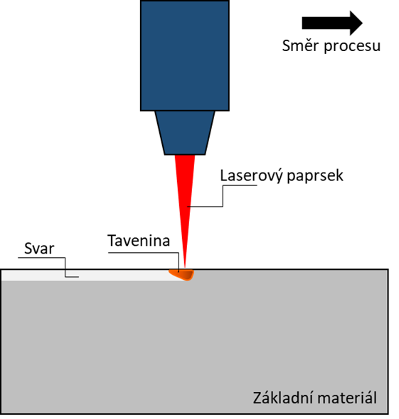
Power, speed, spot size, fit-up and melt-pool support must work as one system.
Image: TRUMPF GmbH + Co. KG via Wikimedia Commons, CC BY-SA 3.0.Burn-through is a system problem, not one bad setting.
The top bead can look attractive while the root sags, drops through or contains a hidden void. Start with the four decisions below before changing pulse frequency or duty cycle.
Average delivered power and travel speed set the first-order thermal load. A slower pass usually increases the energy deposited along each millimeter.
A variable joint gap or air layer can reduce heat transfer, destabilize the pool and concentrate melting in the upper sheet.
A smaller spot raises power density. Defocus or wobble may spread energy, but too much can create lack of fusion.
Inspect penetration, root profile, fusion boundary and porosity. Surface appearance alone cannot qualify a process.
Laser welding can intentionally produce full penetration through a thin sheet. The defect begins when the root shape, melt loss or opening no longer meets the drawing and acceptance criteria. That distinction matters: reducing power until the root disappears may replace burn-through with incomplete penetration or lack of fusion.
In practice, operators use “burn-through” for several different conditions. A true hole is obvious, but excessive penetration, a hanging root bead, melt sagging and local drop-through can share a common thermal cause. TWI lists excessive penetration, drop-through and sagging among laser-weld imperfections, and even much thicker full-penetration welds can suffer from gravity-driven sag when the molten pool is not supported.[7]
The fusion zone reaches the root and satisfies the specified profile without unacceptable underfill, sag or melt loss.
The joint remains closed, but the root reinforcement or penetration depth exceeds the permitted limit.
Gravity, capillary forces and keyhole behavior pull unsupported liquid metal below the joint.
The molten sheet opens into a hole or loses enough metal that joint continuity and strength are compromised.
Why the same top bead can hide different root conditions
The camera or operator sees reflected light, plume and the upper surface. The joint root can respond differently because thickness, gap and backing vary below that surface. A smooth crown therefore does not prove adequate fusion or acceptable penetration. For a new procedure, destructive cross-sections are usually the fastest way to connect the visible process with the actual weld geometry.
Thin sheet offers a small thermal and mechanical safety margin.
A laser can move from stable fusion to an open hole with a relatively small change in delivered energy, focus, gap or dwell. Three mechanisms commonly interact.
Local energy exceeds the available melt volume
A thin cross-section contains less metal beneath the beam. When the energy delivered to each millimeter rises, penetration can grow until the remaining liquid film cannot bridge the joint.
The keyhole or pool becomes unstable
Recoil pressure, vapor, surface tension, shielding flow and beam motion shape the keyhole. Instability can eject liquid metal or widen the root opening even when nominal power is unchanged.
The molten metal loses support
An edge joint, poor overlap, open gap, unfavorable welding position or missing backing leaves the liquid pool with less mechanical support. Gravity and pressure then promote sag or drop-through.
Average power divided by speed gives a useful first comparison in joules per millimeter. It is not a complete thermal model because absorptivity, beam profile, spot size, wobble path and losses change how much energy reaches the joint. A 2025 study of 0.2 mm 316L stainless sheet used this relationship to explain why lower travel speed increased local energy and produced burn-through in that specific setup.[1]
Adjust the cause—not the most convenient knob.
Burn-through often appears after a parameter change, yet the parameter may only expose a hidden fit-up or motion problem. Review these groups in order.
Average power, peak power and pulse shape
Average power controls the time-averaged energy supply, while peak power and pulse shape influence coupling and keyhole initiation. In pulse mode, the relationship between these values must be known before frequency or duty cycle is interpreted.
First check: confirm whether the display reports source power, set percentage or measured delivered power.Energy delivered to each millimeter
At constant average power, slowing down raises the nominal energy per unit length. Increasing speed can reduce burn-through, but excessive speed may cause intermittent fusion, undercut or lack of penetration.
First check: review actual robot or hand speed, including corners and starts.Power density at the workpiece
A small spot concentrates power. A controlled defocus can lower peak intensity and broaden the interaction, while excessive defocus can prevent fusion. Focus must be referenced to the real joint surface, not only to a nominal fixture height.
First check: verify focus after changing nozzle, protective window or work height.Gap changes heat flow and pool support
Autogenous laser welding has limited ability to bridge a gap because the spot and fusion zone are narrow. TWI notes that butt-joint gaps are typically kept below about 10% of material thickness as a general laser-welding fit-up guideline, with the actual limit depending on the process.[3]
First check: measure the worst gap under production clamping, not just loose parts.Energy distribution and gap bridging
Beam oscillation spreads energy over a programmed path and can enlarge the effective fusion width. Filler wire can replace missing volume and support gap bridging. Both variables add new interactions and require their own qualification.
First check: confirm oscillation width, frequency, orientation and wire position.Starts, stops, corners and repeated passes
A stationary start, abrupt stop, corner slowdown or overlapping repair pass can deposit far more local energy than the steady-state seam. Heat accumulation also changes later welds on a compact component.
First check: inspect the exact location of the defect relative to the motion program.Myth correction: there is no universal “high frequency + 70–80% duty cycle” recipe.
For ideal rectangular pulses, average power is approximately peak power × pulse duration × frequency, and duty cycle is pulse duration × frequency. Raising frequency only lowers energy per pulse when average power is held constant; if peak power or on-time also changes, heat input may rise. A duty cycle that works on one source, material and waveform is not a universal thin-sheet setting. Record every coupled variable and develop a test window instead of copying one percentage.
The weld mode changes the shape of the risk window.
These diagrams show why the same average power can create different penetration behavior when the intensity distribution and keyhole state change.

“Thin plate” is not one laser-welding condition.
Absorptivity, thermal conductivity, coating, melting range and joint geometry change the route to burn-through. Use this table to plan trials, not to assign universal power settings.
| Material or condition | Why burn-through can appear | First variables to verify | Qualification focus |
|---|---|---|---|
| Stainless steel sheet | Low section thickness and concentrated energy can rapidly create full penetration; slow travel or start-stop dwell can open the root. | Actual speed, power ramp, focus, backing and shielding coverage. | Root profile, undercut, discoloration, porosity and corrosion-related acceptance. |
| Carbon steel sheet | Surface condition and coating change coupling. A gap or unsupported edge can cause melt loss even when nominal power looks conservative. | Coating, cleanliness, fit-up, clamp pressure and seam tracking. | Fusion, undercut, spatter, hardness and any customer-specific coating damage limit. |
| Aluminum alloy | High reflectivity at common fiber-laser wavelengths, rapid heat conduction and a low-viscosity pool can produce a narrow process window. Oxide and alloy chemistry add variability. | Surface preparation, focus, beam motion, speed, filler strategy and joint support. | Porosity, root sag, hot cracking, fusion width and mechanical test results. |
| Copper or brass | High thermal conductivity makes initiation difficult, while changing absorptivity can cause a sudden transition to deep penetration. Brass also introduces volatile zinc and fume concerns. | Source wavelength, beam stability, focus, speed, composition and extraction. | Spatter, porosity, root shape, electrical performance and fume control. |
| Coated or plated sheet | Vaporized coating can pressurize a lap interface or destabilize the pool. A closed interface may trap vapor. | Coating type and thickness, venting gap, joint orientation and waveform. | Internal porosity, expulsion, coating damage and corrosion protection. |
| Dissimilar or thickness-mismatched joint | The thin member reaches the burn-through limit before the thick member reaches the required fusion depth. Unequal absorptivity and conductivity further skew the pool. | Beam offset, power distribution, wobble, wire and heat-sink fixture. | Fusion into both members, intermetallic layer, distortion and strength. |
Research values are setup-specific. For example, published thin-sheet studies use different alloys, joint geometries, beam delivery and motion systems; their power or speed ranges should not be copied as a production recipe.[1][2]
Check the likely burn-through risk.
This diagnostic does not prescribe machine parameters. It helps identify which part of the setup deserves the first controlled test.
Stabilize fit-up before tuning power.
The current combination has several interacting risk factors. A parameter-only correction may hide a mechanical problem.
Develop a stable process window in eight controlled steps.
The fastest route is not random trial and error. Freeze the mechanical condition, then change one optical or thermal variable at a time.
Define the joint and acceptance criteria
Document alloy, temper, coating, actual thickness, seam type, target penetration, permitted root reinforcement and inspection method. A cosmetic top bead alone is not a target.
Measure production fit-up
Check gap, offset and part lifting after the real fixture closes. Clamping must reproduce the condition, not merely hold one laboratory coupon.
Verify optics and focus
Inspect the protective window and nozzle, confirm standoff, locate focus relative to the actual surface and verify that the programmed path follows the joint.
Establish a conservative energy window
Start from a qualified supplier trial or a low-risk test matrix. If penetration is excessive, reduce average power or increase speed in small increments while watching fusion.
Shape the energy distribution
Test controlled defocus or beam wobble when the joint needs a wider, less intense interaction. Do not assume a smaller spot is safer: it increases power density.
Add material or support when needed
For a gap, thin edge or mismatched thickness, evaluate filler wire, beam offset, backing, a chill fixture or a different welding position. Beam oscillation plus wire has improved gap bridging in published thin-aluminum work, but the method requires its own development.[4]
Control starts, stops and corners
Use power ramps, lead-in tabs or synchronized speed-power control. Corner power following can prevent the local heat spike created when motion slows.
Validate the complete production cycle
Section coupons from cold start, warmed-up operation, corners, stops and repaired areas. Confirm that shielding, extraction, optics condition and part variation remain inside the window.
Use the defect location to identify the most likely mechanism.
Make one controlled change, inspect the root and keep a record. Multiple simultaneous changes may produce one good coupon without revealing why.
| Observed symptom | Likely mechanism | First controlled change | Risk of overcorrection |
|---|---|---|---|
| Hole along the whole seam | Linear energy or power density is too high for the section, or focus is more concentrated than expected. | Verify focus and speed; then compare a small power reduction or speed increase. | Incomplete penetration or intermittent fusion. |
| Hole only at the start | Stationary dwell, aggressive ignition, delayed motion or poor start-tab design. | Reduce dwell; add a coordinated power ramp or start outside the part. | An excessively soft ramp may create an unfused start. |
| Hole only at the stop | Motion stops before power decays, or the keyhole collapses without crater control. | Coordinate the downslope with motion and test an exit tab. | Too early a power reduction can leave an unfilled crater. |
| Burn-through at corners | Robot or manual travel slows while power remains constant; heat accumulates at the direction change. | Use corner power following or a smoother motion path. | Low corner power can create local lack of fusion. |
| Intermittent holes | Variable gap, contamination, focus-height variation, part lifting or unstable seam tracking. | Correlate each hole with measured gap and fixture position before tuning power. | Reducing power may hide the symptom but weaken the rest of the seam. |
| Upper sheet melts in a lap joint | An air layer or poor contact limits heat transfer into the lower sheet. A recent ultra-thin ferritic-steel study found burn-through at both low and high power under certain lap-joint conditions, illustrating that the relationship can be non-linear.[2] | Improve contact and clamping; verify focus and beam offset. | Adding power alone can enlarge the hole without improving interface fusion. |
| Wide sagging root without a hole | Full penetration is achieved, but the liquid pool is insufficiently supported or the welding position promotes gravity-driven sag. | Evaluate backing, position, speed and a narrower stable penetration window. | Overcooling or excessive speed may cause root lack of fusion. |
| Spatter followed by a hole | Keyhole instability, contamination, trapped coating vapor or excessive peak intensity ejects melt. | Check surface and interface cleanliness, coating venting, focus and waveform. | Suppressing penetration without solving vapor pressure can preserve internal porosity. |

A macro section reveals penetration depth, root profile and fusion geometry that are invisible from the top surface.
Image by LaserTherm, Wikimedia Commons, CC BY-SA 4.0Prove the process across the whole operating window.
Qualification should connect process settings to the required weld geometry and service performance. ISO 13919-1:2019 defines quality levels for laser- and electron-beam-weld imperfections in steel, nickel, titanium and their alloys at joint thicknesses of 0.5 mm and above. It also makes clear that a quality level is not automatically a fitness-for-purpose decision.[8] Customer drawings and application-specific standards remain controlling.
Prevent recurrence with process controls—not operator memory.
Once the window is qualified, lock the variables that determine heat input and joint support. A good parameter sheet is necessary but not sufficient.
Fixture and gap control
Use hard stops, clamp confirmation and periodic gap measurement. Track wear that changes part height, overlap or contact pressure.
Optics condition
Define inspection criteria for the protective window, nozzle and beam path. Contamination can alter delivered power and focus behavior.
Program governance
Control revisions to power, speed, wobble, wire and start-stop ramps. Record who changed the recipe and why.
Signal monitoring
Where justified, correlate plume, back-reflection, camera or other sensor signals with cross-sectioned defects before setting alarm limits.
Open-beam welding requires appropriate Class 4 laser controls.
Industrial welding lasers can present eye, skin, reflection, fire and airborne-contaminant hazards. OSHA notes that Class 4 lasers can create direct, reflected and diffuse hazards and that laser-generated airborne contaminants require appropriate controls.[9] A fully enclosed, interlocked system may be supplied as a lower-class laser product during normal operation, but servicing and defeated-interlock states require separate assessment.
Beam containment
Use an engineered enclosure or controlled laser area with interlocks, warning systems, restricted access and a documented nominal hazard zone.
Eye and skin protection
Protective eyewear must match the actual wavelength and required optical density. It supplements engineering controls; it does not replace enclosure.
Fume and fire control
Capture welding fume at the source, assess coatings and alloy constituents, remove combustible materials and provide process-appropriate fire protection.
Connect the defect diagnosis to the machine, material and test.
Use these pages to move from general troubleshooting to a representative sample weld and equipment recommendation.
Handheld Laser Welding Machine
Review the handheld welding system route for fabrication and repair work.
Explore machines → ApplicationStainless Steel Laser Welding
Plan appearance, penetration, shielding and production requirements for stainless joints.
View the application → ApplicationAluminum Laser Welding
Understand the added challenges of reflectivity, oxide, porosity and pool stability.
View the application → ValidationRepresentative Sample Testing
Use the actual alloy, thickness, joint and acceptance criteria to qualify a starting route.
Plan a sample test →Laser welding burn-through FAQ
The correct answer depends on the real source, optics, waveform, material and joint. These answers give a defensible diagnostic direction.
Why does laser welding burn through thin metal?
Thin metal provides little melt volume and a narrow thermal margin. Burn-through occurs when energy delivery, keyhole behavior, gap, joint support and motion combine to remove or drop more molten metal than the joint can retain.
Should I reduce laser power first?
If penetration is excessive along a consistent seam, a small reduction in average power may be appropriate. First verify focus, speed and fit-up. When holes are intermittent or location-specific, fixture or motion problems are often the better first target.
Does faster welding always stop burn-through?
At constant average power, faster travel reduces nominal energy per unit length and often reduces penetration. Too much speed can create incomplete fusion, intermittent penetration or undercut, so the change must be confirmed in cross-section.
Does a higher pulse frequency always reduce burn-through?
No. Pulse frequency cannot be interpreted alone. If average power is fixed, more pulses per second generally means less energy per pulse. If peak power, pulse duration or average power also changes, total energy delivery may rise instead. Record the complete waveform.
Is 70–80% duty cycle ideal for every thin plate?
No universal duty-cycle percentage applies to all lasers or joints. Duty cycle interacts with peak power, frequency, pulse duration, beam motion, speed and material. Develop a qualified window on representative samples.
Should I use a smaller laser spot for thin sheet?
Not automatically. A smaller spot increases power density and may deepen penetration or destabilize the keyhole. Controlled defocus or wobble can distribute energy, but excessive spreading can cause lack of fusion.
Why does a lap joint burn through even at relatively low power?
Poor contact or an air gap can interrupt heat transfer into the lower sheet, allowing the upper sheet to overheat. Coating vapor trapped at the interface may add pressure. Improve fit-up and contact before simply adding more power.
Can filler wire prevent burn-through?
Wire can add metal volume, bridge a controlled gap and change pool behavior. It also introduces wire position, feed speed, chemistry and fusion requirements. It is a process-development option, not an automatic cure.
Can wobble welding reduce burn-through?
Wobble can spread energy across a wider path and improve tolerance to some fit-up conditions. The pattern, width, frequency, orientation and travel speed must be developed together; too much wobble can reduce penetration or enlarge the heat-affected area.
How do I stop holes at starts and stops?
Coordinate laser power with motion. Use an upslope after motion begins and a downslope before motion ends, or place starts and stops on lead tabs where the design permits. Then section those transitions separately.
Can shielding gas flow cause burn-through?
Gas flow is usually not the primary heat-input control, but excessive or poorly directed flow can disturb a small molten pool. Inadequate shielding can oxidize the weld. Verify nozzle position, flow quality and extraction interaction while keeping the thermal variables controlled.
What information should I send for a thin-sheet welding trial?
Provide exact alloy and temper, coating, minimum and maximum thickness, joint drawing, actual gap range, desired penetration, cosmetic limits, strength or leak requirements, cycle time, welding position, filler preference and available inspection criteria.
References and further reading
- Metals (2025): Laser welding of 0.2 mm 316L stainless steel. The paper relates average power and travel speed to heat input and reports the tested speed-dependent transition between burn-through and partial penetration.
- Metals (2025): Ultra-thin ferritic stainless lap-joint welding. This study shows that air-gap heat transfer and joint behavior can make burn-through non-linear rather than a simple high-power-only defect.
- TWI: Increasing laser-welding tolerance to joint fit-up. Discusses the narrow spot, strict fit-up and the role of clamping, filler and beam manipulation.
- Physics Procedia: Gap bridging in thin aluminum using beam oscillation and filler wire. Study-specific evidence for combining oscillation and added material to improve gap tolerance.
- Quarterly Journal of the Japan Welding Society: Oscillating laser beam welding. Describes control of heat-input distribution through beam oscillation.
- Materials: Thin 316L laser welding and focus distance. Demonstrates in the tested setup that focus position changed spot size and penetration behavior.
- TWI: Low-porosity full-penetration laser welding of aerospace aluminum. Includes discussion of penetration, welding position and sag/drop-through control.
- ISO 13919-1:2019. Quality levels for imperfections in electron- and laser-beam-welded joints in steel, nickel, titanium and their alloys.
- OSHA: Laser hazards. Summarizes Class 4 direct, reflected, diffuse, fire and laser-generated airborne-contaminant hazards and control principles.
Send the joint, gap and quality target—not just the plate thickness.
Oceanplayer can review a thin-sheet laser-welding application and help define a practical equipment and sample-test route. The best request includes the real alloy, joint, fit-up range, production target and acceptance method.