

Handheld Laser Welder + Cobot: Low-Cost Automation?
A handheld laser welder paired with a cobot can be a lower-complexity route into welding automation—but only when the job is repeatable, the parts can be fixtured consistently, the joint fit-up is controlled and the complete laser cell is made safe.
The cobot does not turn a variable manual process into a stable one by itself. The investment case depends on usable arc-on time, changeover, fixture repeatability, rework avoided, qualified weld quality and the cost of the enclosure, extraction, integration, training and validation—not merely the price of a robot arm or laser source.

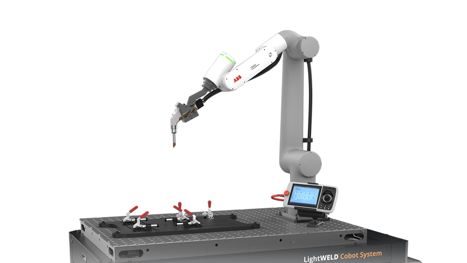
Image source: IPG Photonics LightWELD Cobot System.
Automate a stable task—not a moving target.
The strongest first application is a family of parts with recurring welds, accessible paths, predictable loading and measurable quality. A poor candidate has warped parts, changing gaps, reflective hazards that are not contained, frequent one-off geometry or a cycle dominated by manual handling rather than welding.
Choose a part that returns often enough for programming, tooling and validation effort to be reused.
The robot repeats the programmed path; it cannot compensate for uncontrolled part location or gap without sensing and process development.
Include the cobot, laser, tooling, wire, shielding gas, enclosure, extraction, controls, installation and training.
Robot safety functions do not contain direct or reflected Class 4 laser radiation, welding fume or hot-work hazards.
A handheld laser welder + cobot is a complete production cell.
The phrase can sound as simple as bolting a welding gun onto a robot. A production-ready solution is an integrated machine with several subsystems that must work together and stop safely together.
The laser, optics, nozzle, shielding-gas delivery and optional wire feeder define the welding process. The interface must support robotic start/stop, schedule selection and fault handling.
Payload, reach, path behavior, tool-center-point calibration and cable routing determine whether the torch can access every joint without singularities, collisions or excessive wrist motion.
Datum surfaces, clamps, loading access and mistake-proofing keep each joint where the program expects it. Tooling often determines more of the outcome than the programming interface.
Laser-rated containment, interlocks, emergency stops, fume capture, shielding gas, electrical supply and operating procedures are part of the cell—not optional accessories to solve after delivery.
Ask whether the quoted scope includes the welding table, fixtures, wire feeder, enclosure or barriers, interlocks, fume extraction, gas equipment, freight, commissioning, training, sample development, qualification support and spare parts. Two visually similar systems can represent very different delivered capability.
Handheld, Cobot or industrial robot: which route fits?
A cobot fills the space between a manually guided welder and a dedicated industrial robot cell. It is not automatically the cheapest answer; it is valuable when flexibility and repeatable robotic motion matter more than maximum speed.
| Configuration | Best fit | Main advantage | Main constraint | Planning question |
|---|---|---|---|---|
| Manual handheld laser welder | One-offs, repair, highly variable parts and work that benefits from human adaptation | Fast changeover and direct operator judgment | Quality and output remain operator-dependent; the person stays in the process | Can a trained operator safely reach and control every joint? |
| Open Cobot integration | Large or accessible parts, repeat jobs and layouts where a separately controlled laser area can be created | Maximum access and flexible loading | Requires laser-rated barriers or room controls, interlocks, hazard analysis and controlled access | Can direct and reflected beams be contained throughout the complete robot envelope? |
| Enclosed Cobot cell | Small-to-medium parts, predictable loading and shops wanting a contained turnkey footprint | Containment, interlocked access and extraction can be integrated into one machine | Part size, loading method and robot reach are limited by the enclosure | Will the enclosure accept the largest part and preserve efficient loading? |
| Traditional industrial robot cell | High-volume, long production runs, large payloads and demanding cycle-time targets | Higher speed, payload and dedicated automation capability | More engineering, space, guarding and changeover effort | Is the annual volume stable enough to justify dedicated automation? |
Planning interpretation informed by IPG Photonics’ integration guide. Final classification and safeguards depend on the delivered system and site risk assessment.
Pass these six gates before asking for a Cobot price.
The fastest way to waste an automation budget is to price hardware before defining the part, joint, process window and production target. Score the application first.
Repeat frequency
List annual quantity, batch size and how often the job returns. A small batch can still fit if programs and fixtures are reused; a one-off job may not recover programming and qualification time.
Part consistency
Measure the actual tolerance of stampings, bends, cut edges and assemblies. Automation needs repeatable datums. Warpage and dimensional drift move the joint away from the taught path.
Joint fit-up
Record gap, offset and edge condition across representative parts. Laser welding generally demands tighter fit-up than arc processes, especially for autogenous welding without filler wire.
Path access
Map torch angle, stand-off, approach and escape motion at every joint. The arm needs more than nominal reach: it needs a collision-free posture and room for the welding head, cable and wire path.
Quality evidence
Define penetration, fusion, bead profile, porosity, distortion, appearance and any destructive-test requirements. “Looks clean” is not a production acceptance standard.
Labor opportunity
Separate touch time, loading, tacking, welding, inspection, grinding and rework. The cobot only saves time in activities the cell actually changes; it does not eliminate all labor around the part.
If the application cannot hold the joint in a repeatable location during a sample test, do not assume robot repeatability will solve it. Improve part preparation, forming, fixture design or sensing before building the business case.
The robot repeats the path; the fixture repeats the joint.
Laser welding cobots perform best when part dimensions, clamping and weld paths remain consistent. IPG’s integration guidance specifically identifies repeatable fixturing, predictable paths and fit-up as central application conditions.

Fast robot motion cannot recover time lost locating, clamping, checking and reworking inconsistent parts.
Image source: IPG Photonics.
Define three-dimensional datums that stop translation and rotation without over-constraining the part. Avoid referencing a cosmetic or thermally unstable edge unless it is controlled.
Clamping must maintain contact without blocking the beam, shielding gas, wire, extraction nozzle or robot path. Check whether heat causes the seam to open during welding.
Use keyed fixture locations, stored programs, documented tool-center-point checks and verification coupons so the cell returns to a known state after a product change.
Wire can increase process tolerance and fill a wider joint, but adds a feeder, consumables, alignment variables and maintenance. Validate both autogenous and wire-fed routes where appropriate.
Touch sensing, vision or seam tracking can help specific deviations, but each adds integration and cycle time. Do not use expensive sensing to compensate for a fixture problem that can be removed mechanically.
Robot position proves where the arm went. It does not prove penetration, fusion or porosity. Connect process records to weld inspection and traceability requirements.
Lead-through teaching is easy; production programming is more than waypoints.
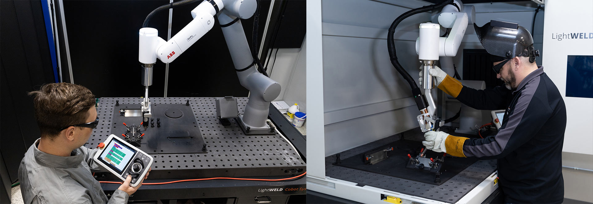
Modern cobots can simplify motion teaching through manual guidance, jogging and graphical program blocks. The production job still requires safe approaches, torch orientation, weld schedules, gas timing, wire coordination, fault recovery and a dry run.

A practical teaching sequence
Begin at a safe home position, teach clearance moves, define the approach, orient the torch, teach weld start and end, assign the qualified schedule, coordinate gas and wire, then teach a safe retreat. Run the full path with emission disabled before any live weld. Confirm that cables, wire conduit and extraction follow the motion without snagging.
What makes changeover fast
Fast changeover comes from named programs, revision control, fixture identification, stored schedules, keyed tooling, inspection records and a repeatable calibration check. “Programming in minutes” can describe basic motion teaching; it does not include first-article approval, parameter development or safety validation.
A collaborative arm does not make the laser process collaborative.
The robot may provide power-and-force limiting and safe motion functions, but the application also contains invisible laser radiation, specular reflections, hot metal, shielding gas, fume, wire movement, pinch points and stored energy. The integrated cell must be risk-assessed as a whole.
An enclosure can contain the process only when its materials, viewing panels, seams, doors, interlocks and beam paths are designed and validated for the actual laser.
Image source: IPG Photonics.
| Hazard | Why the Cobot feature is insufficient | Planning controls to evaluate |
|---|---|---|
| Direct and reflected laser radiation | Robot torque sensing cannot detect or attenuate a hazardous beam or reflection | Laser-rated enclosure/barriers, beam termination, interlocked access, warning systems, controlled area, trained personnel and wavelength-specific eyewear where required |
| Robot and tooling motion | Payload, sharp workpieces, fixtures and process tools change the application risk | Application risk assessment, safe zones/speeds, separation monitoring, validated stop functions, collision review and safe loading sequence |
| Welding fumes and gases | Compact cells can concentrate contaminants; an open shop is not proof of adequate ventilation | Source capture, designed airflow, filter selection, exposure assessment, maintenance indicators and compliant discharge or recirculation |
| Fire, hot parts and spatter | The robot can continue cycling while a hot-work condition develops | Combustible control, fire-resistant surfaces, temperature/part-handling plan, fire protection, inspection and emergency response |
| Service and fault recovery | Personnel may enter the cell or approach stored energy during troubleshooting | Lockout/tagout procedure, safe service mode, authorized access, documented restart, interlock testing and controlled parameter permissions |
ISO 10218-2:2025 addresses integration, commissioning, operation, maintenance and decommissioning of industrial robot applications. OSHA laser guidance gives engineering controls primary consideration for limiting access to laser radiation, while OSHA’s laser technical manual calls for adequate ventilation for fumes and vapors from laser welding. Apply the regulations and standards relevant to the installation location.
“Low cost” means lower integration burden—not a universal system price.
Online prices for a standalone welder or robot arm do not describe a commissioned welding cell. Request a line-item scope and compare the total installed capability over the same period.
Include the laser source, welding head, cobot, control cabinet, industrial base or table, mounting hardware, cables and any license required for automated operation.
Price the wire feeder, drive components, nozzles, protective windows, shielding-gas equipment, chiller where applicable, extraction unit and initial consumables.
Include laser-rated enclosure or barriers, viewing windows, interlocks, access control, emergency stops, safety controller, signage, validation and exposure assessment.
Budget for part studies, weld trials, tooling, robot reach study, process development, destructive testing, documentation and first-article approval.
Account for delivery, site preparation, electrical and gas work, commissioning, operator/programmer training and production ramp time.
Include optics, nozzles, filters, coolant, calibration, service labor, software, spare parts, preventive maintenance and the cost of waiting for a critical imported component.
Prices change with laser power, robot reach and payload, country, certification, enclosure design, tooling complexity and service scope. A responsible supplier should explain what the quoted cell can process, what remains for the buyer to provide and what evidence is included at acceptance.
Calculate payback from accepted parts and recovered capacity—not headline weld speed.
Laser travel speed is only one component of the cycle. The cell also approaches, starts gas, loads wire, welds, retracts, waits for loading, inspects and changes products. Use observed time and accepted output.
Build the annual benefit
Start with the current baseline for the same accepted part. Measure direct welding labor, setup, grinding, rework, inspection, scrap and constrained capacity. Then model the new cell using realistic utilization, changeover and staffing—not 100% uptime.
Count hours that can be reassigned or avoided, not every minute the robot is moving.
Use historical defect cost and a validated pilot result; do not assume automation eliminates defects.
Include grinding or polishing only when the qualified laser weld actually reduces it.
Additional output has value only when orders, downstream capacity and staffing can absorb it.
Use a transparent equation
Annual net operating benefit should subtract the cell’s power, gas, wire, consumables, maintenance, support and incremental labor from the verified annual savings and contribution of additional accepted output.
Run conservative, expected and demand-limited scenarios. If payback only works with perfect uptime, zero changeover, no fixture cost and every extra part sold, the business case is fragile.
Open the Cobot ROI CalculatorWhere a laser welding Cobot is strong—and where it struggles.
A good application does not need to be mass production. It needs enough repetition and process stability to reuse the work invested in fixtures, programs and qualification.
| Application condition | Fit | Reason | What to prove |
|---|---|---|---|
| Recurring stainless or carbon-steel sheet assemblies | Strong candidate | Repeat seams, accessible joints and stable fixtures can support reusable programs | Fit-up tolerance, shielding, bead acceptance, distortion and load/unload time |
| High-mix, low-volume part families | Promising | Graphical programming and stored recipes can reduce the burden of product changes | Fixture commonality, changeover time, program revision control and first-piece verification |
| Large parts with repeated accessible seams | Conditional | An open integration can provide access beyond a compact enclosure | Laser containment across the full envelope, robot reach, cable routing and safe loading zones |
| Thin aluminum assemblies | Test required | Laser welding can limit heat input, but material, oxide, gap, gas and porosity risk require process development | Metallography or mechanical acceptance, porosity, cracking, wire choice and surface preparation |
| Irregular repair work or one-off fabrication | Usually better handheld | Human judgment may adapt faster than programming and fixturing each unique part | Whether the same path will recur enough to justify automation |
| Warped parts with unpredictable gaps | Poor starting point | The taught path and process window may not follow the real joint | Can upstream forming, fixturing, filler wire or validated sensing make the joint repeatable? |
| Very high-volume dedicated production | Compare industrial robot | A traditional cell may deliver higher speed, payload and integrated automation | Annual volume, takt time, uptime requirement and product-life stability |
An eight-step integration path for a first laser welding Cobot.
The order matters. If the team buys hardware before proving the joint and safety concept, late fixture and containment changes can erase the expected low-cost advantage.
Select one representative part family
Provide drawings, material specifications, thickness, joint design, annual quantity, batch size, current cycle time, quality requirement and photographs. Include worst-case variation—not only the best sample.
Prove laser process feasibility
Develop an initial weld window on representative parts. Record laser power, travel speed, wobble, focus, wire, gas and surface preparation. Test the result against the actual acceptance criteria.
Measure part and gap variation
Inspect multiple production parts. Identify whether failures come from cutting, forming, assembly, tacking or clamping. Decide what must change upstream before automation.
Design fixtures and material flow
Define datums, clamps, loading sequence, part presence checks, mistake-proofing and operator ergonomics. Estimate manual handling separately from robot cycle time.
Complete reach and cycle study
Model the torch angle, robot posture, cable and wire routing, safe approaches and all welds. Include gas pre-flow, indexing, loading, inspection and changeover.
Engineer the complete safety concept
Assess laser, robot, hot-work, fume, gas, electrical and service hazards. Select containment, interlocks, safe motion, extraction and operating controls for the actual layout.
Build and validate the cell
Commission utilities, calibrate the tool center point, prove programs with emission disabled, run controlled trials and test safety functions. Establish acceptance samples and process records.
Ramp with ownership and metrics
Train an internal owner and operators. Track accepted parts per hour, changeover, downtime, consumable use, defects and maintenance. Improve the real bottleneck rather than only increasing travel speed.
Plan what surrounds the Cobot before it arrives.
Utility and workflow assumptions vary by model. Confirm all requirements from the exact supplier drawings and local codes rather than copying a voltage, gas flow or ventilation value from another system.
Confirm voltage, phase, frequency, branch protection, grounding, disconnects and demand for laser, robot, chiller, extraction and accessories.
Confirm gas type, purity, pressure, peak flow, cylinder or bulk supply, regulators, hose routing and low-supply response.
Define source capture, required airflow, filter stages, filter loading indication, noise, make-up air and discharge/recirculation approval.
Verify floor loading, leveling, anchors or locking casters, transport route, maintenance clearance and any effect of moving the cell on calibration.
Plan loading, egress, interlocked doors, viewing, warning lights, emergency stops, key control and who may enter, program, service or restart.
Decide how programs, schedules, approvals, maintenance, alarms and part quality records will be backed up and linked to production.
Stock approved protective windows, nozzles, seals, wire-path parts, wire, filters and supplier-recommended critical spares by lead time.
Name the person responsible for process recipes, tooling, safety checks, backups, training, acceptance and supplier communication.
Ask for evidence, scope and support—not only specifications.
A cobot’s nominal reach, payload and repeatability do not tell you whether the delivered cell can weld your part safely at the required quality and takt time.
| Purchase question | What a useful answer contains | Evidence to request |
|---|---|---|
| Which of our parts were evaluated? | Material, thickness, joint, gap range, size, access and production variation | Sample report, parameters, photos, video and inspection results |
| What exactly is included? | Laser, robot, table, fixture, wire, gas, extraction, containment, controls, installation and training | Line-item scope, responsibility matrix and exclusions |
| How was cycle time calculated? | Robot motion, gas timing, welding, loading, inspection, changeover and expected utilization | Cycle breakdown and live demonstration on a representative part |
| How is safety engineered? | Applicable standards, risk assessment scope, laser containment, interlocks, safe robot functions and extraction | Drawings, safety-function list, validation plan, declarations and manuals |
| How is the process maintained? | Optics inspection, nozzle/wire alignment, TCP calibration, filter service, backup and preventive maintenance | Maintenance schedule, consumables list, spare-parts availability and training outline |
| What happens after installation? | Commissioning, acceptance, response time, remote support, field service, software access and escalation | Service terms, warranty, regional capability and named acceptance criteria |
| Can the system grow? | Program transfer, future parts, arm options, fixtures, wire modes, automation interfaces and data | Upgrade path, interface documentation and example expansion scope |
Agree the material, part revision, fixture, quantity, weld acceptance, cycle definition, safety checks, documentation and pass/fail rules before the test. A demonstration on a convenient supplier sample does not prove your application.
Six myths that weaken a Cobot welding project.
Collaborative robot features address robot-motion hazards under defined conditions. A hazardous laser process may still require full containment, barriers, interlocks and a controlled area.
Graphical programming can simplify motion creation, but fixtures, weld qualification, safety functions, calibration, recovery and production control still require engineering.
The arm can return to the same position while the seam has moved. Improve part consistency or validate sensing against the measured variation.
Output includes loading, approaches, gas, wire, inspection, changeover and downtime. Measure accepted parts per shift, not only millimeters per second.
Presets are starting points. Material grade, thickness, surface, gap, gas, focus, wire and acceptance requirements define the qualified window.
A missing fixture, enclosure, extraction package, training or acceptance study can reappear later as delays, rework and unplanned integration cost.
Send the part—not just the desired laser power.
For a useful Cobot recommendation, provide drawings, material and thickness, joint details, gap range, annual quantity, batch size, current cycle time, quality criteria, part photos and the available cell space. Oceanplayer can use that information to recommend a manual, Cobot or robotic route and define the next sample test.
Handheld laser welder + Cobot FAQ.
Can a handheld laser welder be mounted on any Cobot?
Not safely or effectively by default. The welding system must support automated control, the robot must have suitable payload, reach and path performance, and the mounting, tool-center point, cables, wire feeder, shielding gas, faults and safety functions must be integrated. Use a supplier-approved interface or an engineered integration validated for the exact components.
Is a laser welding Cobot cheaper than a traditional robot cell?
It can have a lower integration burden and smaller footprint for flexible, moderate-volume work, but there is no universal price advantage. Compare complete installed scope: laser, robot, tooling, enclosure, extraction, controls, utilities, commissioning, training, maintenance and qualification. A traditional robot may be more economical for high-volume, cycle-time-driven production.
What jobs are best for a laser welding Cobot?
Strong candidates have recurring welds, consistent part dimensions, repeatable fixtures, predictable paths, accessible joints and measurable labor, rework or capacity constraints. High-mix low-volume production can fit when programs and fixtures are reused. Irregular repairs, highly warped parts and constantly changing one-offs are usually weaker first projects.
Does a Cobot laser welder need a safety enclosure?
The answer depends on the complete hazard assessment and delivered classification. An open Class 4 laser process requires engineered control of direct, reflected and scattered radiation, access and other hazards. Many installations use a laser-rated interlocked enclosure or a controlled room with suitable barriers. Robot collaborative features alone do not provide laser containment.
Can operators work beside the Cobot while it is laser welding?
Do not assume so. Personnel location and access must be defined by the cell risk assessment, laser classification, containment, interlocks, safe robot functions, process hazards and local requirements. An operator may load or teach near a stopped system, while active welding may require the person to be outside an interlocked enclosure or controlled beam area.
Do I need robot programming experience?
Many cobots support lead-through teaching, jogging and graphical blocks that reduce the coding barrier. Production ownership still requires training in coordinate systems, tool calibration, weld schedules, fixture control, safe recovery, program revisions and quality. Easy motion teaching does not remove the need for welding and integration knowledge.
How fast can a laser welding Cobot be programmed?
A simple path may be taught quickly, but full deployment takes longer. The first production program includes part study, fixture development, parameter trials, safe approaches, dry runs, qualification, cycle optimization and documentation. Reusing stable fixtures, recipes and program templates makes later changeovers faster.
Can the Cobot compensate for joint gaps and warped parts?
Only within a validated process and sensing strategy. Filler wire can improve tolerance for some gaps, while touch sensing, vision or seam tracking may address defined variation. None is a universal substitute for consistent parts and fixtures. Measure the real variation first, then prove the chosen method on worst-case samples.
How do I calculate Cobot welding payback?
Divide total installed investment by verified annual net operating benefit. Benefit may include labor hours genuinely released, rework and scrap avoided, finishing reduced and contribution from realizable additional output. Subtract power, gas, wire, consumables, maintenance, support and incremental labor. Use conservative utilization and demand assumptions.
What determines the correct Cobot reach and payload?
Payload must include the welding head, mount, cables, wire accessories and any other arm load with the required safety margin. Reach must be checked at every weld with the correct torch angle, approach, wrist posture and fixture. A nominal reach number alone does not prove collision-free access or acceptable path behavior.
What should be tested before buying a laser welding Cobot?
Test representative and worst-case parts for fit-up, reach, fixture repeatability, weld parameters, cycle time, distortion, appearance, penetration, fusion and defects. Review loading, changeover and extraction. Agree measurable acceptance criteria, safety validation scope and documentation before the purchase order or factory acceptance test.
Can one Cobot weld stainless steel, carbon steel and aluminum?
A suitably specified laser system may process multiple materials, but each material, thickness and joint needs a validated schedule and compatible shielding gas, filler wire, optics and surface preparation. Prevent cross-contamination where it affects quality, control program access and retain qualification records for each released combination.
Sources used for this planning guide.
Manufacturer capability statements describe particular systems. Site safety, weld acceptance and economic performance must be established for the actual installation and application.
- IPG Photonics — LightWELD Cobot System
- IPG Photonics — Laser Welding Cobots: Tips for Successful Integration
- IPG Photonics — Programming Laser Welding Cobots: Basics & Overview
- IPG Photonics — Laser Welding Cobots: A Complete Guide
- ISO — ISO 10218-2:2025, Safety Requirements for Industrial Robot Applications and Robot Cells
- ABB — GoFa Collaborative Robot Capabilities and Safety Features
- OSHA — Guidelines for Laser Safety and Hazard Assessment
- OSHA Technical Manual — Laser Hazards and Ventilation