Why Does Metal Expand When Heated? Thermal Expansion Explained
Metal usually expands when heated because added thermal energy increases atomic vibration and, due to the asymmetric forces between atoms, their average separation becomes slightly larger. The atoms do not simply swell; billions of microscopic spacing changes add together to increase the part's length, area and volume.
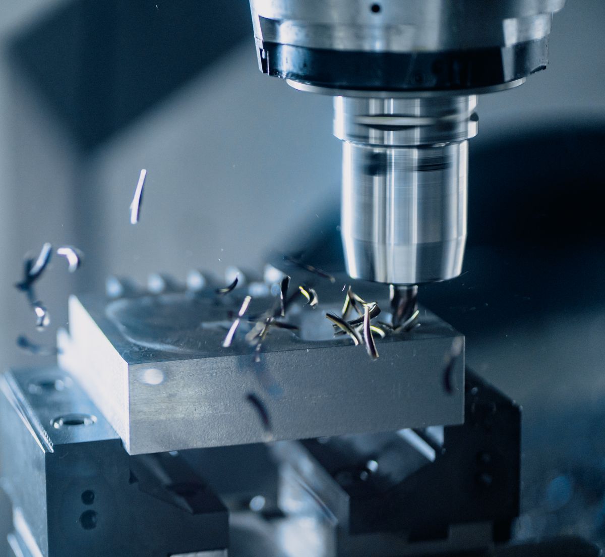
Photo by Bence Szemerey via Pexels.
Heating increases lattice vibration; anharmonic bonding shifts the time-averaged atomic separation outward.
It is a planning equation for a known material, suitable CTE and approximately uniform temperature.
A freely heated bar grows without ideal thermal stress; restraint converts the natural strain into force.
Alloy, condition, direction, temperature interval and phase stability determine the value engineers should use.
Heat changes the equilibrium spacing inside the metal
A metal may look motionless, but its atoms continuously vibrate around lattice positions. Raising temperature increases this vibrational energy. Because the interatomic energy curve is steeper when atoms are pushed too close than when they are pulled slightly apart, the average spacing generally shifts outward.
Calculation: 12 × 10⁻⁶/K × 10 m × 80 K = 0.0096 m. That movement is real even though the change at each atomic spacing is extremely small.
Cooling normally reverses the dimensional change while the alloy remains in the same stable phase and within a recoverable range. A part may not return exactly to its starting dimension if the cycle also causes yielding, creep, stress relief, phase transformation, oxidation, damage or permanent distortion.
This distinction matters in bridges, rail, process piping, machine tools, turbines, electronic packages and welded assemblies. The free-growth equation predicts a dimension change; it does not by itself prove that a support, joint, weld, flange or expansion bellows is safe.
Metal thermal expansion calculator
Estimate free movement, hot dimension, thermal strain, optional differential movement and an ideal full-restraint elastic stress. Preset coefficients are educational near-room-temperature values; edit the CTE and modulus fields when qualified project data are available.
Define the member and temperature cycle
Use actual metal temperature rather than heater setting or ambient air temperature whenever accuracy matters.
The calculator assumes homogeneous material, approximately uniform temperature, small strain and a constant mean CTE over the interval. It does not calculate piping flexibility, buckling, creep, fatigue, weld distortion, support loads or code compliance.
A 10 m carbon-steel member heated uniformly from 20 °C to 100 °C grows to approximately 10.0096 m if it can move freely.
The atoms vibrate more—but anharmonic bonding is the decisive reason
“Atoms move faster and need more room” is a useful shortcut, but it leaves out the physics that creates a larger average spacing. If the interatomic force behaved like a perfectly symmetric spring, vibration could increase without moving the average position.
Atoms remain associated with lattice positions, but their vibrational amplitude grows as thermal energy rises.
Short-distance repulsion rises steeply, while the attractive side is shallower. The time-averaged separation therefore shifts outward.
A long component contains an enormous number of atomic spacings, turning a tiny shift at each bond into measurable millimetres of movement.
Most engineering metals have positive CTEs over ordinary service ranges, but it is not a universal law at every temperature and direction. Magnetic transitions, crystal-structure changes and specially engineered negative-expansion materials can produce very low, nonlinear or locally negative expansion. NASA has reported negative-CTE alloys developed to compensate movement in ultra-stable structures.
Choose the formula that matches the dimension you are estimating
For small, free and approximately uniform changes in an isotropic material, expansion scales with the initial size, temperature change and the relevant coefficient. These are first-order estimates—not substitutes for a stress, fatigue, creep or stability analysis.
Use for length, width, height, outside diameter or bore diameter when a suitable mean linear CTE is available.
Fractional length change. A strain of 600 µε means 600 micrometres of change per metre of original length.
Small-strain isotropic approximation. Both in-plane dimensions expand, while the much smaller squared term is neglected.
Small-strain isotropic approximation using β ≈ 3α. It is not a universal rule for anisotropic crystals or composites.
| Unit form | Meaning | How to use it correctly |
|---|---|---|
| K⁻¹ or °C⁻¹ | Fractional linear change per degree of temperature change. | A 1 K interval equals a 1 °C interval, so the numerical coefficient is the same. |
| µm/(m·K) | Micrometres of movement per metre per kelvin. | Numerically equal to parts per million per kelvin and convenient for engineering tables. |
| 10⁻⁶/K | Fractional change in millionths per kelvin. | A value of 12 means 12 µm of change per metre for each 1 K rise. |
| µin/(in·°F) | Microinches per inch per degree Fahrenheit. | The numerical per-°F coefficient equals the per-K value divided by 1.8. |
| Cumulative expansion | Total relative change from a stated reference temperature. | Prefer manufacturer or code tables over one constant when the temperature range is broad. |
An instantaneous CTE is the local slope of the length-temperature curve. A mean CTE describes a stated interval. NIST SRM 736, for example, shows that pure copper's expansivity changes with temperature. Do not silently apply a “20–100 °C” value to cryogenic or furnace service.
How much do common metals expand?
The chart uses representative near-room-temperature values in µm/(m·K) to show relative scale. “Steel,” “stainless steel” and “aluminum” are material families, not single guaranteed properties. Use the exact grade, product condition, direction and temperature range for design.
What the comparison means
For the same length and temperature rise, aluminum typically moves about twice as much as ordinary carbon steel near room temperature. A 1 m aluminum member may grow roughly 2.3 mm over a 100 K rise, while a representative carbon-steel member grows roughly 1.2 mm.
Low expansion is not automatically “better.” Material selection must also consider strength, stiffness, conductivity, corrosion, processability, operating temperature, joining compatibility, availability and cost. Invar provides dimensional stability in a limited regime but is not a universal substitute for steel or aluminum.
High thermal conductivity can reduce temperature gradients, yet it does not eliminate free expansion. Copper can become more uniform in temperature than stainless steel while still changing dimension according to its CTE.
Why different metals expand at different rates
CTE emerges from bonding, lattice dynamics, crystal symmetry, magnetic state, alloy composition, phase stability and processing history. It cannot be predicted reliably from density, strength, melting point or thermal conductivity alone.
Bond stiffness
A deep, stiff energy well generally resists spacing change, while stronger anharmonicity can increase the shift in average distance.
Crystal direction
Cubic polycrystals are often treated as isotropic; non-cubic crystals, texture and product direction can make expansion anisotropic.
Alloy chemistry
Solute atoms, phases and magnetic interactions modify the energy landscape. Invar uses magnetic effects to suppress ordinary expansion.
Temperature
CTE usually changes as temperature rises, and phase or magnetic transformations can create sharp departures from a smooth curve.
Condition
Cold work, porosity, residual stress, precipitation, heat treatment and additive-manufacturing texture can influence measured behavior.
Phase transformations change more than CTE
When steel changes crystal structure during heating or cooling, ordinary thermal expansion is joined by transformation strain. Heat-treatment dilatometry therefore reveals metallurgical events as well as reversible temperature-driven movement.
Likewise, precipitation, recovery, recrystallization, oxidation, creep and stress relief can create permanent or nonlinear dimensional change. A reading taken during a thermal cycle may contain several mechanisms, so it should not automatically be called thermal expansion.
Specify alloy grade, governing specification, product form, condition, direction, reference temperature and operating interval. A generic “stainless steel CTE” is not a controlled property requirement.
Four examples show how small strain becomes important movement
These examples use representative CTE values for explanation. The arithmetic estimates free, uniform movement; every real assembly still needs boundary conditions, tolerances, gradients and applicable design rules.
Using α = 12 × 10⁻⁶/K and a 40 K rise. Anchors, bearings, rail neutral temperature and installation condition determine the real response.
Using α = 23 × 10⁻⁶/K and a 70 K rise. A steel scale on the same frame grows only about 1.68 mm in this simplified comparison.
Using α = 17 × 10⁻⁶/K and a 200 K rise. This is free axial growth, not an allowable equipment-nozzle displacement.
Using α = 23 × 10⁻⁶/K and a 150 K rise. Uniform heating can create temporary assembly clearance for an interference fit.
Does a hole in metal expand when heated?
Yes. Under uniform, unconstrained heating, a hole becomes larger. Imagine the hole temporarily filled with the same metal: the imaginary plug would expand with the plate, so its diameter would increase. Removing the plug does not change the surrounding material's scale change.
The same linear relationship applies to bore diameter when the material is homogeneous, approximately isotropic, heated uniformly and free to move. This is why heating an outer ring—or cooling an inner shaft—can create temporary clearance for shrink-fit assembly.
The intuitive answer can fail when only one region is heated, the ring is externally clamped, the wall is thin or asymmetric, the product is directionally textured, or the cycle causes yielding, phase transformation or creep. In those cases the hole may become oval or distort instead of scaling uniformly.
Control actual part temperature, soak time, uniformity, metallurgical limits, coatings, lubricants, seals and handling time. Never heat a precision or heat-treated component to an arbitrary temperature merely because αLΔT predicts enough clearance.
Free expansion changes dimension; restraint creates thermal stress
A straight bar that heats uniformly and can slide grows without needing an ideal internal force. If rigid supports prevent that movement, compression develops during heating and tension develops during restrained cooling.
The member changes length. Sliding supports, clearances, loops and flexible connections are intended to preserve a controlled degree of movement.
- No ideal axial restraint force
- Still check contact, friction and available travel
- Temperature gradients can create local stress even when the ends are free
For steel with E = 200 GPa, α = 12 × 10⁻⁶/K and ΔT = 50 K, the ideal elastic stress magnitude is 120 MPa.
- Heating creates compression; cooling creates tension
- Real systems may slip, yield, buckle, creep or relax
- Support stiffness and geometry determine actual restraint
Thermal gradients cause warping and shock
When one region heats faster than another, the hotter material tries to expand more. Compatibility with the cooler region creates self-equilibrating stress and curvature. Thick plates, brake rotors, rolls, dies, furnace parts, engine components and welded assemblies can distort or crack without external anchors.
Faster heating, low thermal conductivity, greater thickness and sharp geometry changes increase the risk. Peak temperature alone is therefore an incomplete thermal-design variable; rate, dwell, distribution and cooling path matter too.
CTE mismatch loads bonded materials
Two attached materials with different CTEs prefer different free lengths. Their simplified differential free strain is (α₁ − α₂)ΔT. Bonding converts that mismatch into bending, shear, peel, fastener load or interfacial stress.
This mechanism affects aluminum-to-steel assemblies, solder joints, coatings, electronic packages, metal-to-ceramic seals, bimetal thermostats and clad products. Repeated thermal cycling can cause fatigue even when one cycle appears acceptable.
A weld zone heats and tries to expand against cooler surrounding metal, then contracts during cooling. Gradients, plasticity, fixture stiffness, phase transformation and joint geometry create distortion and residual stress. The free-expansion formula helps explain the driving strain, but it cannot predict final weld shape by itself.
Where metal thermal expansion becomes a design requirement
The same atomic mechanism appears in many systems, but the engineering response changes with geometry, restraint, pressure, tolerance, temperature distribution and cycle count.
Piping
Risks include nozzle load, support lift-off, flange leakage, fatigue, buckling and expansion-joint pressure thrust.
Bridges and rail
Seasonal movement affects joints, bearings, seals, rail force, track buckling and installation settings.
Machines
Warm-up changes alignment, scale position, spindle length and dimensional accuracy at the workpiece.
Turbomachinery
Rotor, casing, blade and seal growth control hot clearances and startup or shutdown rub risk.
Heat exchangers
Tube-to-shell differential movement can load tubesheets, joints, supports and connected equipment.
Furnaces
Frames, liners, doors and refractories need gaps, sliding details and hot-strength material selection.
Weldments
Localized heating and cooling produce distortion, residual stress and mismatch across dissimilar joints.
Electronics
CTE mismatch drives solder fatigue, delamination, substrate cracking and wire-bond or seal damage.
Bolted joints
Different bolt and grip CTEs can change preload, contact pressure, fit and separation margin.
Shrink fits
Controlled heating or cooling creates temporary clearance, followed by interference after temperatures equalize.
Seven ways engineers control thermal expansion
The objective is rarely to “stop” expansion. Good design gives the movement a safe path, reduces the driving temperature difference, matches interacting materials or verifies that the complete assembly tolerates the cycle.
Allow movement
Use intentional clearance, slip joints, slots, sliding bearings, roller supports and flexible hoses.
Redirect it
Pipe loops, offsets, elbows, flexible geometry, guides and anchors send movement toward acceptable directions.
Absorb it
Engineered bellows, metallic hoses, flexible couplings and compliant interfaces require system-level design.
Match CTE
Select compatible materials, use compliant layers or isolate dissimilar parts from damaging mismatch strain.
Reduce gradients
Control ramp rate, improve insulation, balance heat input, add cooling distribution or increase soak time.
Compensate
Machine tools and metrology systems use warm-up routines, sensors, maps and low-CTE references.
Verify assembly
Thermal-cycle testing captures contacts, friction, seals, fasteners, gradients and real boundary conditions.
A bellows or joint may introduce pressure thrust, spring force and stability requirements. Its rated movement, effective area, anchors, guides, supports, installation setting and surrounding structure must work together. The manufacturer's certified design data and the governing code control the real application.
How thermal expansion is measured—and what buyers should specify
A credible CTE value belongs to a defined material, specimen, direction, temperature interval and test method. Published handbook numbers are useful for early planning; acceptance and safety-critical work need traceable data and documented assumptions.
Precision dimensional work commonly references 20 °C. NIST illustrates that even a modest difference between part temperature and reference temperature can create micrometre-level measurement error.
Common measurement routes
Push-rod dilatometry: ASTM E228 covers comparative linear-expansion measurement for rigid solids. Calibration, specimen temperature and apparatus correction are essential.
Thermomechanical analysis: ASTM E831 uses small specimens and programmed thermal scans. Probe load, indentation and precision limits matter, especially for very-low-CTE materials.
Interferometry: ASTM E289 supports high-precision measurements, including low or matched CTE systems, but requires specialized optical and temperature control.
Assembly thermal-cycle testing: Measuring the complete product captures real contacts, gradients, seals, fasteners and friction. The result is system-specific and may include creep, slip or irreversible change.
RFQ and drawing inputs that prevent ambiguity
Grade, specification, product form, condition, direction and required lot traceability.
The dimension, datum and installation or inspection temperature at which it applies.
Minimum, normal, startup, shutdown, upset and maximum metal temperatures—not only process setpoint.
Length, diameter, wall, critical gaps, attached materials, coatings, adhesives, seals and fasteners.
Supports, guides, anchors, friction, preload, joint stiffness and allowed degrees of freedom.
Temperature uniformity, ramp rate, dwell, cycle count, vibration and external loading.
Hot-state clearance, alignment, sealing, contact, electrical or optical requirement.
CTE source, interval, test method, uncertainty, governing code, customer standard and acceptance plan.
When αLΔT is enough—and when it is not
| The simple formula works well when | Use a higher-level method when |
|---|---|
| The part is homogeneous, free to move and heated approximately uniformly. | Supports, contact, pressure, fasteners, welds or surrounding structure restrain movement. |
| The temperature interval is moderate and a suitable mean CTE is available. | The interval is broad, cryogenic, furnace-level or crosses a phase or magnetic transformation. |
| Only first-order movement is needed for preliminary clearance or travel sizing. | Stress, fatigue, creep, buckling, sealing, nozzle load, rotor dynamics or life must be demonstrated. |
| Geometry is simple and behavior is approximately isotropic. | The part is textured, laminated, bonded, clad, porous, composite or additively manufactured. |
| Dimensions and properties remain stable through the thermal cycle. | Yielding, creep, relaxation, oxidation, precipitation, stress relief or permanent set can occur. |
| The result is clearly documented as an estimate. | A contract, code, drawing or safety case requires certified data, uncertainty or qualified analysis. |
Common thermal-expansion mistakes
Grade, condition and temperature interval change the property. Austenitic stainless expands more than carbon or ferritic steel.
The component temperature may lag, overshoot or vary spatially. Measure the metal where the calculation depends on it.
Free movement needs clearance; stress requires restraint, gradient or incompatible attached materials.
A dimension without its reference or installation temperature can create assembly and inspection disputes.
Contraction can create tension, loss of preload, seal leakage or brittle-fracture exposure even if the hot case looks safe.
Welding is local, transient and constrained. Phase change, plastic strain and cooling contraction dominate final distortion.
Related Oceanplayer engineering resources
Use these pages when the temperature problem is connected to welding heat input, material selection, equipment choice or process validation.
Metal thermal expansion FAQ
Why does metal expand when heated?
Heating increases atomic vibration. Because real interatomic forces have an asymmetric energy curve, the average spacing between neighboring atoms generally becomes slightly larger. Those tiny spacing changes accumulate across the part.
Do atoms themselves get bigger when metal is heated?
No. The useful engineering explanation is that the average distance between atoms increases; the atoms are not simply swelling like balloons.
What is the formula for thermal expansion of metal?
For free linear expansion over a moderate temperature range, use ΔL = αL₀ΔT. Here α is the mean linear coefficient for the interval, L₀ is original length and ΔT is temperature change.
What units are used for coefficient of thermal expansion?
Common units are K⁻¹, °C⁻¹, 10⁻⁶/K and µm/(m·K). Values per kelvin and per degree Celsius are numerically equal because the temperature intervals are the same size.
Does aluminum expand more than steel?
Usually yes near room temperature. Representative aluminum CTE is roughly 23 µm/(m·K), compared with about 12 for carbon steel, so equal lengths of aluminum often move about twice as much for the same temperature change.
Which metal has the lowest thermal expansion?
Low-expansion Fe-Ni alloys such as Invar 36 are common engineering choices near room temperature. Their low CTE depends on composition, heat treatment and temperature range; no material is the lowest under every condition.
Does a hole in metal get larger or smaller when heated?
With uniform, unconstrained heating, the hole gets larger. Its diameter follows the same fractional linear expansion as the surrounding material.
Does metal return to its original size after cooling?
Usually, if the material stays in the same phase and the cycle does not cause yielding, creep, stress relief, oxidation, damage or transformation. Those mechanisms can leave a permanent dimensional change.
Can thermal expansion crack metal?
Free uniform expansion does not create ideal thermal stress, but restraint or a temperature gradient does. Repeated thermal stress can contribute to distortion, yielding, fatigue or cracking.
What happens if heated metal cannot expand?
Compressive stress develops during restrained heating. The real response may include support movement, yielding, buckling, slip, creep or relaxation rather than the ideal elastic stress predicted by EαΔT.
Is coefficient of thermal expansion constant?
No. CTE changes with temperature and may also vary with alloy, phase, condition and direction. A constant value is an approximation over a stated interval.
Why are precision dimensions referenced to 20 °C?
Dimensional metrology needs a common reference because parts and instruments change size with temperature. Unless another value is specified, 20 °C is the conventional reference for dimensional and geometrical properties.
How does thermal expansion affect welding?
The hot weld region tries to expand against cooler surrounding metal and then contracts as it cools. Gradients, restraint, plasticity and phase changes can generate distortion and residual stress.
Why do bridge and piping expansion joints need guides and anchors?
Guides define the intended movement path, while anchors separate movement zones and resist loads such as bellows pressure thrust or spring force. Without the correct surrounding system, a joint may overtravel, misalign, become unstable or transfer damaging load elsewhere.
Sources used for the engineering guidance
Representative values and equations support planning and education. Confirm the current controlled standard, code edition, product data and project-specific requirements before design or acceptance.
- Princeton University: Thermal Expansion and Anharmonicity.
- MIT: Atomistic Explanation of Thermal Expansion.
- OpenStax University Physics: Thermal Expansion.
- NIST SRM 736: Copper Thermal Expansion.
- NIST Reference Tables: Selected Material Properties.
- NIST Engineering Metrology Toolbox: Temperature and Dimensional Measurement.
- ASTM E228: Linear Thermal Expansion by Push-Rod Dilatometer.
- U.S. Department of Energy Fundamentals Handbook: Thermal Stress.
- Federal Highway Administration: Bridge Elements and Expansion Joints.
- ASME B31.3 Process Piping: Scope and Flexibility Context.
- NASA: Negative-Expansion Alloy for Ultra-Stable Structures.
- NIST: CTE Mismatch in Joined Electronic Materials.
Validate heat-sensitive fit-up, distortion and joint quality on real parts
The equation explains the driving movement, but a welded assembly also contains gradients, fixtures, gaps, phase changes and cooling contraction. Oceanplayer can review your material and joint, then use a sample test to help identify a practical laser-welding process window.
- Exact alloy, condition and surface state
- Part dimensions, thickness and joint geometry
- Reference and operating temperature range
- Fixture, restraint and mating materials
- Allowed distortion, gap and acceptance criteria
- Production volume and cycle-time target