

Essential Laser Welding Parameters for Beginners
The right laser welding parameters are not one number on a chart. They are a controlled combination of power, travel speed, focus, beam motion, shielding, wire delivery, joint fit-up and surface condition.
Begin with the machine supplier's approved preset for the exact material, thickness and joint. Change one variable at a time on representative coupons, record the result and qualify the complete process before production. This guide explains what every major control does—and the safest order in which to tune it.
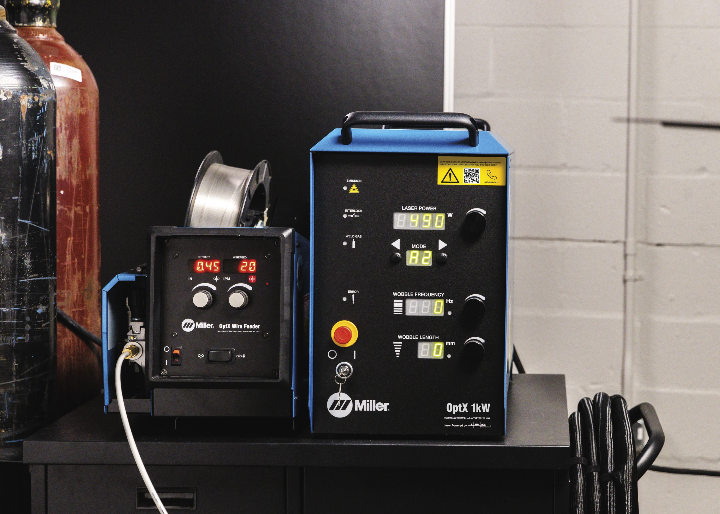
Image source: Miller OptX handheld laser welding system.
Stability comes before maximum power.
A sound starting process produces repeatable fusion without excessive spatter, collapse, oxidation or distortion. More power can deepen a weld, but power alone cannot correct poor focus, changing gaps, dirty material, unstable wire delivery or inadequate shielding. Treat the weld as a complete system.
Match the exact machine, material family, thickness, joint type, nozzle and process mode before making changes.
Power controls available energy; travel speed controls how long each length of joint receives it.
These settings shape energy distribution, weld width, pool behavior, surface protection and gap-bridging ability.
Appearance is evidence, not acceptance. Verify penetration, fusion, dimensions and required mechanical performance.
What counts as a laser welding parameter?
A machine setting is only one layer. The same displayed values can produce different welds when the optics, nozzle, part geometry, gas delivery or material condition changes. Organize the process into four control layers before troubleshooting.
Laser power, mode, duty cycle where applicable, travel speed, spot size and focus determine how energy reaches each length of joint.
Wobble length, frequency, pattern and torch path redistribute that energy across the seam and influence pool movement.
Shielding gas, nozzle position, wire alloy, wire diameter, feed rate and extraction support a stable weld pool.
Material grade, thickness, coating, cleanliness, joint gap, edge condition, fixture rigidity and heat sinking define the operating window.
A useful parameter record includes the machine and firmware, program or mode, power, speed, wobble, focus or stand-off convention, nozzle, shielding gas, flow at the point of use, wire, joint, material heat or lot, fixture and inspection result. “1500 W at speed 5” is not a transferable welding procedure.
Inputs you can command
These are values the operator or program can intentionally set: laser output, motion speed, scan pattern, gas timing, wire feed and sometimes pulse or duty-cycle variables. Confirm whether the display shows an absolute value, percentage or program index.
Conditions you must control
Gap, alignment, surface films, focus calibration, lens condition, gas leaks and workpiece temperature may not appear on the control panel, yet they can dominate the result. Check them before compensating with energy.
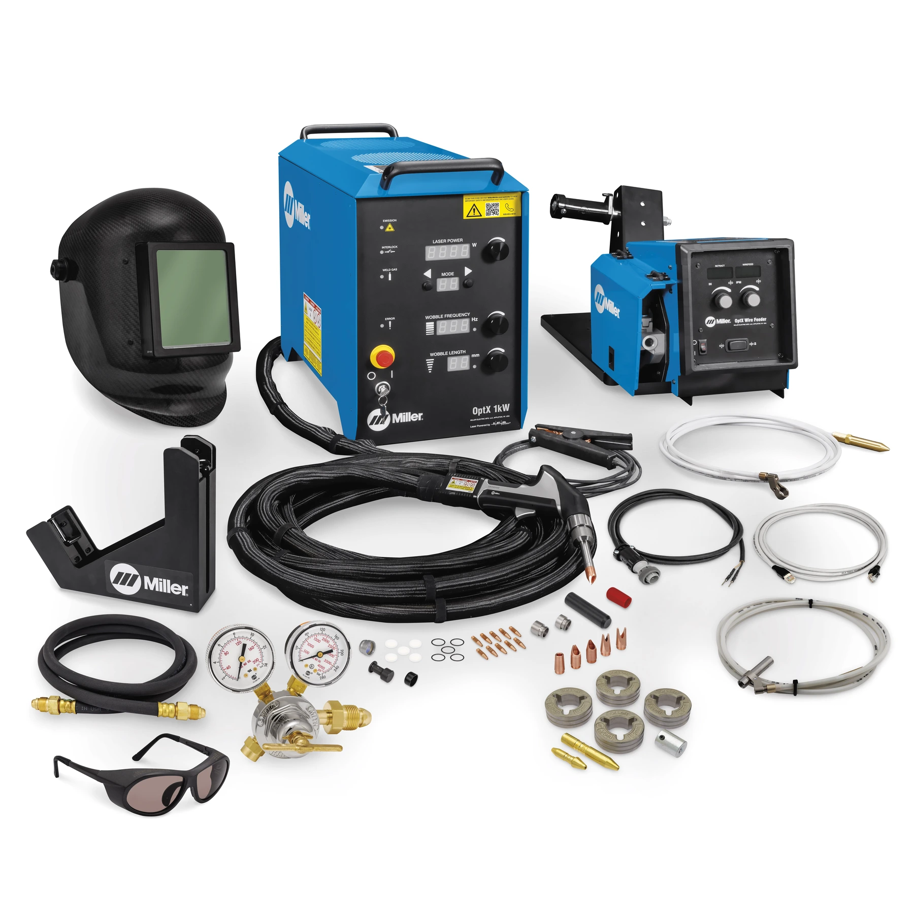
The display does not describe the whole process.
Two machines showing the same wattage can differ in beam profile, optics, focus convention, wobble pattern, control logic, duty behavior and delivered power. The torch, nozzle, cable, gas path, wire feeder, firmware and safety interlocks are part of the parameter set.
When a procedure is transferred to another machine—even one with the same rated power—treat it as a new validation exercise.
Image source: Miller OptX handheld laser welder.
Laser power and travel speed must be read together.
Average laser power describes the energy rate available from the source. Travel speed changes the interaction time. Their ratio provides a useful first planning indicator, but it does not describe spot area, absorption, wobble, joint efficiency or the energy actually coupled into the metal.
Line energy is a comparison tool
For a continuous process moving at a steady speed, a simple nominal line-energy calculation is:
Line energy (J/mm) ≈ laser power (W) ÷ travel speed (mm/s)
If power stays constant and speed falls, nominal energy per millimeter rises. If speed stays constant and power rises, it also rises. Use the relationship to understand the direction of a change—not to copy a process between machines.
Open the Welding Heat Input CalculatorExample for comparison—not a recipe
At 1,200 W and 30 mm/s, the nominal line energy becomes 40 J/mm. That does not guarantee less penetration: a smaller spot, different focus, changed beam profile or a more absorptive surface can still alter power density and coupling.
Record actual workpiece speed and the machine's meaning of “power.” A percentage is only meaningful when the source's maximum output and program behavior are known.
| Change | Likely first effect | What can go wrong | What to verify |
|---|---|---|---|
| Increase laser power | More available energy and often greater penetration or a larger pool. | Spatter, undercut, edge collapse, burn-through, excessive root reinforcement or distortion. | Penetration, bead profile, root condition and whether optics or shielding remain stable. |
| Decrease laser power | Lower energy density and often a smaller, cooler pool. | Lack of fusion, intermittent bonding, unmelted wire or unstable keyhole behavior. | Interface fusion, minimum penetration and wire melting—not only top-bead appearance. |
| Increase travel speed | Less interaction time and lower nominal line energy. | Narrow bead, incomplete fusion, humping, underfill or inconsistent root formation. | Continuity along starts, stops, corners and locations with changing heat sink. |
| Decrease travel speed | More energy per unit length and a longer molten-pool residence time. | Overheating, oxidation, excessive width, collapse, distortion and enlarged heat-affected zone. | Color, geometry, root profile, dimensional change and whether speed is actually steady. |
Technical context: TWI discusses the interdependence of laser power, welding speed, beam delivery and process conditions in laser welding development. See TWI process-parameter research.
The eight settings that shape the weld.
Not every system exposes every value. Handheld machines may combine several internal variables under a stored program, while integrated production cells can expose far more detail. Always use the terminology and limits in the current machine manual.
Power must be high enough to create and maintain the intended fusion mode, yet low enough to avoid collapse, violent vaporization and excessive heat. Reflective alloys, coatings, edge joints and changing heat sinks can narrow the stable window.
- Change in small, documented increments.
- Inspect the root or cross-section after each meaningful change.
- Do not use extra power to compensate for a dirty lens or changing gap.
Speed is a process variable, not merely an output target. Manual travel must remain uniform through starts, ends and corners. In automation, programmed speed may differ from actual speed during acceleration or tight path changes.
- Mark a known distance and time practice passes.
- Use run-on and run-off tabs when the joint permits.
- Watch for local overheating at pauses and direction changes.
Focus position changes spot size and energy concentration. A smaller spot can raise power density; a larger spot distributes energy over more area. The meaning of positive and negative focus varies by manufacturer, so record the physical direction rather than relying on a sign alone.
- Confirm nozzle-to-part stand-off and focus calibration.
- Inspect the protective lens before changing energy.
- Repeat the same torch angle and contact condition.
Wobble can widen the fusion zone, improve tolerance to small fit-up variation and create a broader visual bead. It does not make large or inconsistent gaps acceptable, and an excessive pattern can reduce penetration by spreading energy too widely.
- Start with the supplier's joint-specific pattern.
- Increase width only with penetration evidence.
- Center the pattern on the true joint line.
Frequency interacts with travel speed and wobble width. A change can affect pool agitation, surface rippling and local dwell distribution even when power stays constant. Pattern names and maximum ranges are system-specific.
- Change width and frequency independently during trials.
- Watch for periodic defects that follow the scan pattern.
- Save approved combinations as controlled programs.
Some systems offer continuous fusion, tack, stitch or pulsed modes; others hide pulse controls inside presets. Peak power, pulse width, repetition rate and duty cycle must be interpreted together. Do not assume a “short pulse” is automatically safer for every thin sheet.
- Use only modes documented for welding.
- Confirm whether displayed power is peak or average.
- Qualify start, stop and overlap behavior.
Gas type, purity, nozzle geometry, delivery angle, pre-flow and post-flow all matter. Too little coverage admits air; too much velocity can create turbulence or disturb the pool. Argon, helium or other gases may be specified depending on material and process.
- Follow the machine and procedure specification.
- Check leaks, regulator condition and actual point-of-use flow.
- Judge the result by oxidation and quality—not sound alone.
Wire alloy, diameter, feed speed, entry angle and position must match pool capacity. Too much wire can remain cold or push the pool; too little can leave underfill or fail to bridge the intended gap. The wire tip should enter the energetic part of a stable pool.
- Center and align the wire before changing feed speed.
- Match filler metallurgy to the qualified requirement.
- Confirm feeding remains smooth through the full torch path.
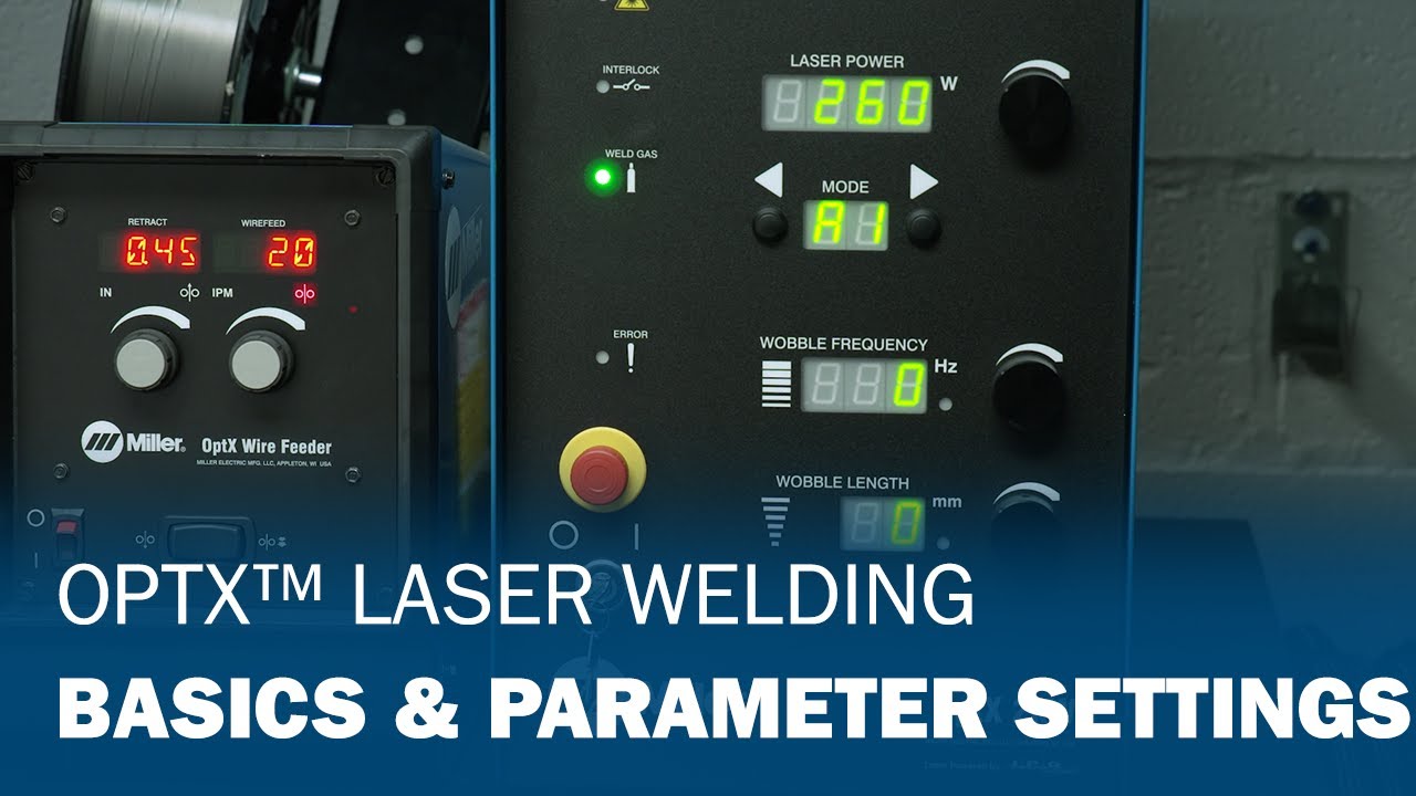
Controls that share a name can operate differently across machines. Verify limits, units, program logic and safety interlocks in the current manufacturer documentation.
Training image source: Miller OptX laser welding basics and parameter settings.
Why changing one control changes several outcomes.
A parameter window is the region where fusion, geometry, metallurgy, appearance and productivity all remain acceptable. The following matrix shows common interactions, but it is a diagnostic map—not a universal adjustment chart.
| Parameter pair | What the pair controls | Typical failure when unbalanced | Better diagnostic question |
|---|---|---|---|
| Power + travel speed | Nominal energy delivered per unit length and the ability to sustain fusion. | Burn-through at high energy; lack of fusion at low energy. | Is the problem present through the entire joint or only where actual speed changes? |
| Power + spot size/focus | Power density and distribution at the workpiece. | Unstable penetration, excessive spatter or a wide shallow bead. | Is focus calibrated and is the lens/nozzle condition unchanged? |
| Wobble width + power | Energy spread across the joint versus energy available for penetration. | Attractive wide bead with incomplete interface fusion. | Does a cross-section confirm fusion at both edges and the root? |
| Wobble frequency + speed | Beam revisit density along the joint. | Periodic ripples, uneven width or inconsistent pool behavior. | Does the defect spacing follow the programmed scan or motion cycle? |
| Gas flow + nozzle geometry | Coverage, plume removal and local flow behavior. | Oxidation at low coverage; turbulence or pool disturbance at excessive velocity. | Is gas reaching the hot zone, including the trailing solidification region? |
| Wire feed + power/speed | Whether filler melts, transfers and fills at the rate the pool can accept. | Cold wire, balling, underfill, excessive reinforcement or spatter. | Is wire position correct before the feed rate is changed? |
| Joint gap + wobble/wire | Gap bridging and deposited cross-sectional area. | Intermittent fusion, sagging, underfill or root opening. | Is the gap within a controlled range along every production part? |
| Surface condition + all energy settings | Absorption, gas generation, contamination and stability. | Porosity, spatter, inconsistent penetration and rapid protective-lens contamination. | Did the material, coating, oil or cleaning method change between coupons? |
If power, speed, wobble and gas are changed together, the next bead may look better but the cause remains unknown. Hold the setup constant, change one controlled factor, record the result and return to the last stable baseline when the trend reverses.
A disciplined route from preset to approved process.
This sequence assumes trained personnel, an approved laser-controlled area and a machine in serviceable condition. It is not a substitute for a welding procedure specification, manufacturer training or the required safety assessment.
Define the acceptance target first
Write down material specification, thickness, joint type, gap tolerance, required penetration, allowable reinforcement or undercut, surface appearance, distortion limit and required mechanical or leak testing. Without acceptance criteria, parameter optimization becomes cosmetic.
Freeze the physical setup
Use representative coupons, the production nozzle, verified optics, correct shielding route, controlled fixture, intended wire and the real part orientation. Clean the surfaces consistently and document coatings or plating. A trial on bright scrap may not represent an oily production part.
Load the closest approved preset
Select the supplier program for the machine, material family, joint and thickness. Confirm units and mode. Stored presets are starting points, not automatic qualification, but they reduce the risk of beginning far outside a stable operating range.
Establish stable fusion without wire
When the intended joint allows fusion welding, first prove that power, speed, focus and beam motion create a repeatable pool. Observe starts and stops. If filler is required by the design, introduce it only after the underlying energy and path are stable.
Correct gross energy before cosmetics
Use penetration evidence to decide whether the power-speed-focus combination is fundamentally low or high. Do not widen wobble simply to hide an unstable root. Change one primary energy variable at a time and keep the last acceptable coupon.
Tune width, shielding and filler
Once fusion is repeatable, refine wobble, gas coverage and wire delivery to meet width, appearance and fill requirements. Verify the effect at corners, starts, stops and heat-sink transitions—not only in the middle of a straight bead.
Challenge the edges of the window
Test realistic high and low gaps, thickness tolerance, fixture variation, operator travel and surface condition. A process that works only on the perfect coupon is not ready for production. Define alarms, reaction plans and requalification triggers.
Lock, label and train
Save the approved program, restrict unauthorized edits, identify the nozzle and consumables, create a setup sheet and train operators to recognize drift. Record inspection evidence and revision history so successful settings remain reproducible.
Why there is no universal laser welding settings chart.
Material name and sheet thickness do not fully define the process. Alloy grade, temper, coating, reflectivity, joint geometry, clamping, heat sink, laser wavelength, beam profile and actual spot can all shift the operating window.
| Application variable | Why it matters | Starting strategy | Evidence required |
|---|---|---|---|
| Carbon or stainless steel | Alloy, surface scale, shielding and heat input influence fusion, oxidation, hardness and appearance. | Use the exact machine's steel preset; control surface state and gas coverage. | Cross-section, bead geometry, hardness or mechanical tests when required. |
| Aluminum alloy | Reflectivity, oxide film, thermal conductivity, alloy chemistry and hot-cracking sensitivity vary widely. | Identify alloy and temper; clean consistently; evaluate filler and joint restraint with a qualified welding engineer. | Fusion, porosity, cracking, strength and dimensional inspection. |
| Copper or brass | High reflectivity and conductivity complicate coupling; volatile zinc in brass adds porosity and fume risk. | Confirm the system is rated for the alloy and thickness; use controlled trials and source capture. | Sectioning, porosity inspection, mechanical performance and fume-control verification. |
| Galvanized or coated metal | Coating vapor can destabilize the pool and create porosity or spatter; overlap gaps affect venting. | Identify coating mass and joint design; follow a developed procedure rather than treating it as bare steel. | Internal porosity, coating damage, spatter, strength and exposure controls. |
| Butt joint | Alignment and gap directly affect bridging and root formation. | Control edge quality, mismatch and gap before increasing wobble or filler. | Root continuity, alignment, penetration and underfill. |
| Lap joint | Beam position, top-sheet thickness and interface condition govern fusion area. | Locate the interface precisely and control overlap/contact; do not judge only by the top bead. | Interface width, penetration into lower sheet, peel or shear performance as specified. |
| Corner or fillet joint | Edge heat concentration, torch access, filler placement and shielding coverage change quickly. | Use the intended nozzle and work angle; verify actual path speed through the corner. | Leg size, root fusion, edge melt-back and surface oxidation. |
Current commercial systems publish their own material and thickness capabilities and provide stored presets. Compare the machine-specific scope on the IPG LightWELD capability page and the relevant manual rather than transferring values blindly.


Read the defect as a clue—not a diagnosis.
Different causes can produce similar visual symptoms. Begin with setup and condition checks, then make controlled parameter changes. If the weld carries structural, pressure, electrical, safety or regulatory requirements, escalate to the responsible welding engineer.
| Observed symptom | Check before changing settings | Parameter directions to investigate | Proof needed |
|---|---|---|---|
| Lack of fusion or shallow penetration | Wrong preset, focus/stand-off error, dirty lens, actual speed too high, joint misplaced under wobble or poor workpiece contact. | Evaluate power-speed balance, focus and beam centering. Narrow excessive wobble only with controlled trials. | Cross-section or qualified nondestructive test; top-bead width is insufficient. |
| Burn-through, sagging or edge collapse | Part thickness, gap, edge condition, local heat sink, pauses and actual path speed. | Reduce energy per length, correct focus, increase controlled speed or redistribute energy—one variable at a time. | Root geometry, remaining thickness, distortion and repeatability at tolerance extremes. |
| Porosity | Oil, moisture, coating, zinc, trapped joint contamination, gas leak, draft, unstable keyhole and wire condition. | Correct preparation and shielding first; then evaluate stability through power, speed and beam motion. | Internal inspection or sectioning. A clean surface does not prove a pore-free weld. |
| Cracking | Material identity, filler compatibility, restraint, joint design, thickness transition and preheat/interpass requirements. | Do not “tune around” cracking casually. Review metallurgy, filler, thermal cycle and procedure qualification. | Metallographic inspection and required mechanical testing under engineering control. |
| Undercut or underfill | Joint location, torch angle, gap, wire alignment and whether filler delivery is interrupted. | Balance pool size, speed, wobble and filler addition. Excess power can wash edges without filling them. | Profile measurement and minimum effective section along the entire joint. |
| Spatter or unstable plume | Contamination, coating, focus, protective lens, nozzle damage, gas velocity and inconsistent stand-off. | Reduce excessive power density or improve stability through the approved power-speed-focus range. | Lens contamination rate, surface condition, defect frequency and internal weld quality. |
| Dark oxidation or discoloration | Gas type, leaks, coverage, pre/post-flow, nozzle angle, drafts and heat retained after the beam passes. | Improve shielding and reduce unnecessary thermal exposure. Do not simply maximize flow. | Surface acceptance, corrosion requirement and backside condition where relevant. |
| Uneven bead or periodic ripples | Manual travel consistency, wire-feed drag, path acceleration, loose optics and fixture vibration. | Review wobble frequency/width, motion speed and wire-feed stability after mechanical causes are excluded. | Bead periodicity, process log and repeated coupon result. |
When the result changes from coupon to coupon at identical displayed settings, suspect uncontrolled conditions—focus, optics, surface, gap, shielding, motion or machine status—before adding more parameter changes.
How to know the settings are actually correct.
A smooth, bright bead may still hide incomplete fusion, porosity or an unacceptable root. Build an acceptance plan around the product risk and applicable code, specification or customer requirement.
Measure width, reinforcement, undercut, mismatch, distortion, starts, stops and surface condition against defined limits.
Confirm penetration, interface fusion, root shape, internal pores and the real effect of wobble or filler.
Use tensile, peel, bend, shear, fatigue or hardness testing when the design, code or risk requires it.
Verify leak tightness, electrical resistance, corrosion performance, cleanliness or cosmetic criteria relevant to the part.
Run enough samples to cover realistic gap, material and operator variation; one successful coupon does not define capability.
Record the approved window, inspection method, consumables, setup, revision, requalification triggers and reaction plan.
What to send for a sample test
Provide the actual alloy and thickness, joint drawing, gap range, part photos, required weld length, cycle target, filler requirement, surface condition and acceptance criteria. Representative production samples produce better recommendations than generic sheet coupons.
What a useful test should return
Ask for the machine configuration, parameter record, consumables, visual evidence, section or test results, observed risks and the recommended next validation step—not only a short video of a good-looking bead.
Parameter development takes place inside a laser safety system.
Handheld laser welders are commonly Class 4 laser systems. The direct beam, specular and diffuse reflections, hot work, electrical equipment, compressed gas and metal fume must be assessed as one operation. PPE is only one layer.
Use an engineered enclosure or controlled area, interlocks, warning systems, beam-resistant barriers and surfaces selected by a qualified laser safety professional.
Laser eyewear must match wavelength and optical density requirements. Use the manufacturer-specified helmet, protective clothing and hot-work PPE; never rely on ordinary welding PPE alone.
Base extraction on material, coatings, filler and process. Galvanized, painted, plated or alloyed metals can generate hazardous contaminants that require professional exposure control.
Operators need machine, process and emergency training. Parameter access should be limited so a production program cannot be changed without documented approval.
Test the emergency stop, access interlocks, torch contact or plume safeguards and workpiece connection as instructed by the manufacturer before operation.
A new reflective geometry, alloy, coating, fixture or automated motion can change beam paths, fume and hot-work risk even when the displayed welding parameters stay the same.
Safety references: Miller handheld laser safety guidance, OSHA laser hazards directive and OSHA laser chapter.
Send your material, joint and acceptance target.
Oceanplayer can help you shortlist a handheld laser welder and plan a representative sample test. Share the alloy, thickness, joint drawing, gap tolerance, filler requirement, photos and required result so the recommendation starts with your application—not a generic power number.
Related welding guides and tools.
Laser welding parameters: beginner FAQ.
What are the most important laser welding parameters?
Laser power, travel speed, focus or spot condition, wobble width and frequency, process mode, shielding gas, wire feed and joint fit-up are the main controls. Surface cleanliness, nozzle condition, fixture repeatability and actual material grade are equally important even though they may not appear on the control panel.
How do I choose laser power for a new weld?
Start with the current manufacturer preset for the exact machine, material family, thickness and joint. Use representative coupons and the production setup. Adjust power together with travel speed and confirm penetration or interface fusion by sectioning or an approved inspection method. Do not select power from thickness alone.
Should thicker metal always use more laser power?
Thicker metal often needs more energy or different joint preparation, but power is not the only solution. Travel speed, focus, spot, beam profile, alloy, heat sinking, joint geometry and the machine's rated capability all matter. Very thick or demanding joints may be outside a handheld system's qualified range.
What happens when laser welding speed is too fast?
Excessive speed can reduce interaction time and cause a narrow bead, incomplete fusion, underfill, humping or an inconsistent root. Check actual speed through corners and acceleration zones. Increase energy only after focus, path location, joint fit and machine condition are confirmed.
What happens when laser welding speed is too slow?
Slow travel can increase nominal energy per unit length, creating excessive width, oxidation, distortion, edge collapse, burn-through or a larger heat-affected zone. Manual hesitation at starts, stops and corners can create local defects even when average speed appears acceptable.
What is the correct focus position for laser welding?
There is no universal signed value. Focus convention, optics and permissible stand-off vary by machine. Use the manufacturer procedure, record the physical direction and verify calibration. The correct position is the one that produces the required power density and weld geometry with stable optics and repeatable stand-off.
How do wobble width and wobble frequency affect the weld?
Wobble width spreads the beam across a wider seam, while frequency changes how often the scan repeats as the torch travels. Together with power and speed, they influence weld width, pool agitation, appearance and penetration. Excessive width can create a wide attractive bead with insufficient fusion.
Which shielding gas should I use for laser welding?
Use the gas specified by the machine supplier or qualified welding procedure for the exact material and application. Argon and helium are common inert shielding gases, while other gases may be allowed for specific systems and alloys. Gas purity, coverage, nozzle, timing and actual point-of-use flow are as important as the gas name.
How much shielding gas flow is correct?
A universal flow number is unreliable because nozzle size, distance, angle, joint, gas density, drafts and trailing coverage differ. Begin with the equipment or procedure value, verify delivery with a suitable flow device and adjust only after checking for leaks, turbulence, oxidation and pool disturbance.
When should filler wire be used in handheld laser welding?
Wire may be used to fill an approved gap, add cross-sectional area, control metallurgy or meet the joint design. It does not replace gap control. Match wire alloy and diameter to the procedure, then align the wire tip and balance feed speed with pool capacity, laser energy and travel speed.
Can one set of laser welding parameters be used for all metals?
No. Steel, stainless steel, aluminum, copper, brass, titanium and coated materials differ in absorption, thermal conductivity, oxide behavior, cracking risk and fume. Even alloys within one family can require different preparation, filler, shielding and validation. Treat each material-joint combination as a controlled procedure.
How do I know when a laser welding process is ready for production?
It is ready only after the required visual, dimensional, internal, mechanical or functional acceptance has been demonstrated across realistic process variation. Document the approved parameter window, equipment, consumables, setup, inspection plan, operator training and reaction limits; then lock and revision-control the program.
Sources used for this guide.
- Miller — OptX safety, setup and parameter training
- Miller — Current OptX 2 kW handheld laser welder manual
- IPG Photonics — LightWELD system capabilities, presets, wobble and setup
- IPG Photonics — LightWELD XR system datasheet
- TWI — Effect of spot size and beam quality on laser welding performance
- TWI — Focusing optics and power-density considerations
- Linde — Physical and metallurgical roles of shielding-gas components
- OSHA — Guidelines for laser hazards
- OSHA — Laser hazards and ventilation considerations