

Why Is My MIG Welder Spitting and Sputtering?
Irregular popping, wire stubbing and excessive spatter usually point to one of five systems: the wire path, the voltage-to-wire-feed relationship, shielding gas delivery, polarity and work-return continuity, or worn consumables. Diagnose those systems in order instead of turning every knob at once.
.jpg?width=1600)
A stable short-circuit arc can crackle rapidly. The warning sign is irregular stubbing, burnback, feed hesitation, porosity, lack of fusion or a sudden change from a previously qualified setup.
Image: Weldscientist / Wikimedia Commons, CC BY-SA 4.0.
Match the symptom before changing the machine.
"Spitting" can describe several different failures. The most useful clue is what the wire and weld pool do at the exact moment the sound changes.
Stubbing and hard popping
Wire feed may be too high for the selected voltage, the arc may be too short, or wire delivery may be surging.
Burnback after an interruption
Look for restricted feeding, a worn tip, an incorrect start sequence, cable bends or settings that burn wire faster than it advances.
Random sputtering
Inspect the work-return path, gun connection, contact tip, drive system and input supply before assuming the power source has failed.
Porosity with popping
Check gas type, delivery, leaks, drafts, nozzle blockage, excessive stickout and contamination on the wire or workpiece.
Record the existing voltage, wire feed speed, inductance or arc-control value, gas, polarity, wire classification, diameter and contact-tip-to-work distance before adjusting anything. A troubleshooting test is useful only when you know which variable changed.
Is every crackle a MIG welding problem?
No. Short-circuit transfer repeatedly makes and breaks electrical contact as the wire touches the pool. A regular, fast crackle can be normal. A violent, uneven pop accompanied by the wire pushing the gun back, burnback, long pauses or defects is not the same thing.
A pleasant sound does not prove penetration or fusion. A procedure must still meet the required bead profile, joint fusion, mechanical properties and inspection criteria.
Regular short-circuit crackle
The rhythm is consistent, wire feed feels smooth and the bead remains repeatable. Compare with the equipment maker's training material for the selected transfer mode.
Wire repeatedly drives into the pool
This stubbing behavior often means the wire is arriving faster than the arc can melt it under the present voltage, arc-length and inductance relationship.
Sound stops when the gun cable moves
Suspect liner drag, an incorrect drive roll, poor roll pressure, a damaged gun lead or a loose connection before changing the weld schedule.
Popping appears with pores or oxidation
Gas delivery, drafts, nozzle blockage, excessive gas turbulence or contaminated material may be disrupting the protected weld zone.
Find the first system to inspect.
Choose the closest symptoms. The result prioritizes a test route; it does not replace the machine manual, a welding procedure or inspection by a qualified technician.
Describe what happens
Keep the original settings recorded while you run the checks.
The wire appears to be reaching the joint faster than the selected arc can consume it. Return to the charted baseline before making fine adjustments.
- Confirm wire diameter, material and transfer mode.
- Set voltage and wire feed speed from the recommended starting chart.
- Maintain consistent stickout and travel speed.
- Change one setting at a time on clean scrap.
If the machine shows damaged insulation, overheating, repeated protection trips, unstable output with verified inputs or internal arcing, stop and use qualified service.
What makes a MIG welder spit and sputter?
The same visible spatter can come from different mechanisms. Use the secondary clue in the table to avoid correcting the wrong system.
| Observed symptom | Likely systems | First non-destructive check | Avoid this mistake |
|---|---|---|---|
| Wire stubs into the joint | Wire feed too high for voltage; low arc length; surging feeder; excessive stickout | Return to the wire/material chart and watch whether the drive-roll speed is physically steady | Do not increase roll pressure to hide a blocked liner |
| Wire burns back to the tip | Feed restriction; incorrect tip size; start-timing issue; low feed; long arc | Inspect tip bore, liner, roll groove, spool brake and gun cable path | Do not keep welding with wire fused inside the tip |
| Random arc interruption | Loose work return; poor tip contact; gun connection; input or output instability | Clean and relocate the work clamp, inspect connections and compare on clean scrap | Do not open energized panels or bypass protection |
| Spatter plus porosity | Gas loss, draft, leak, blocked nozzle, contamination, excess stickout | Verify the actual gas at the torch, inspect hoses and shield the work from drafts | Do not assume that more flow always improves coverage |
| Excess spatter with self-shielded wire | Wrong polarity, wrong technique, voltage mismatch or incompatible roll/tip | Read the wire manufacturer's polarity and operating-range label | Do not apply the solid-wire DCEP rule to every flux-cored wire |
| Problem appears after warm-up | Duty-cycle limit, thermal protection, failing connection, motor or electronics | Allow rated cooling and compare the actual cycle with the nameplate/manual | Do not defeat thermal protection or continue through burning smells |
Technical context: Miller's MIG defect troubleshooting guide lists shielding, contamination, settings, stickout and contact-tip conditions among spatter causes; TWI's weld-spatter overview also emphasizes voltage/current balance, gas, surface condition, torch angle and wire-feed stability.

Why does the wire jerk, slip or birdnest?
A feeder must push the electrode at a stable rate without crushing it. Too little roll pressure allows slipping; too much can deform wire, load the motor and accelerate liner or tip wear. The correct roll profile also depends on the electrode: smooth V-grooves are common for solid steel wire, knurled rolls are used for many cored wires, and softer aluminum wire may require a purpose-designed system.
Voltage and wire feed speed must work as a pair.
On a constant-voltage GMAW system, wire feed speed strongly influences welding current while voltage influences arc length. The exact response depends on the power source, wire, gas, transfer mode and arc-control settings.
Begin with the door chart, procedure specification or wire manufacturer's range for the exact diameter, material, position, gas and joint. Fine-tune on clean test material of representative thickness.
Voltage / arc length
Too little voltage for the feed condition can promote harsh stubbing and a convex, cold-looking bead. Excessive voltage can create an overlong, wandering arc and undercut or excess spatter.
Wire feed speed / current demand
Increasing feed sends more electrode into the arc and normally raises current demand. If voltage and the rest of the schedule do not support it, the wire may hit the pool.
Inductance or arc control
On short-circuit transfer, inductance changes how quickly current rises during a short. The control name and direction vary by machine, so use the manual rather than assuming a universal setting.
Contact-tip-to-work distance
Changing CTWD changes electrical stickout, resistance heating and actual current. Hold the distance and gun angle consistently before judging a parameter adjustment.
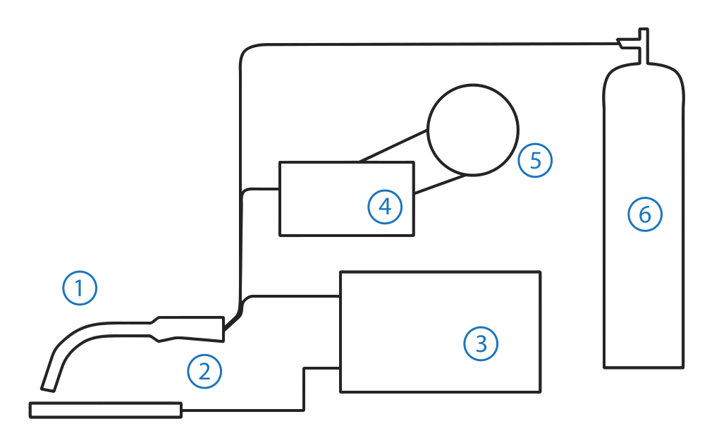
A loose work-return path can imitate a bad power source.
The welding circuit passes through the power source, gun, electrode, arc, workpiece and return lead. Resistance at the contact tip, gun connector, work clamp or cable can interrupt current even when the front-panel settings are correct.
Current transfer point
An oversized, worn or contaminated bore can make electrical contact intermittent. Match tip material and size to the wire and duty.
Clean metal connection
Clamp to sound metal near the work. Paint, rust, scale, loose jaws, hot cable ends and damaged conductors add resistance.
Mechanical and electrical seat
Confirm the gun is fully seated and secured according to the manual. Stop if connectors discolor, arc or overheat.

More gas flow is not always the fix.
Insufficient shielding can cause porosity and oxidation, but excessive flow can create turbulence and draw surrounding air into the gas envelope. Use the equipment and consumable manufacturer's starting recommendation, then verify delivery at the torch under actual conditions.
Pure CO2 is a valid, economical gas for many carbon-steel applications and can provide deeper penetration, but it normally produces a harsher arc and more spatter than an argon-rich blend. It is not simply a "wrong gas."
Inspect cylinder contents, regulator or flowmeter, solenoid function, hoses, gun connections, diffuser and nozzle. Use an approved leak-check method and replace damaged hoses or fittings.
Fans, doors and an extractor positioned too aggressively can pull shielding away. Fume control and gas coverage must be balanced rather than trading one safety or quality problem for another.
Spatter buildup changes the gas pattern. Clean with the proper tool and replace cracked insulators or damaged components.
For process distinctions and shielding-gas influence, see TWI's MIG/MAG overview. Miller's mild-steel guide notes that C25 generally produces less spatter while 100% CO2 can increase penetration and spatter in that application.
The correct polarity belongs to the electrode specification.
Solid wire with external shielding gas commonly runs electrode positive (DCEP). Many self-shielded flux-cored wires require electrode negative (DCEN), while others do not. The wire label, data sheet and machine diagram are the authority.
Often DCEP
Confirm the gun lead is connected to positive and the work return to negative when the selected solid-wire procedure requires DCEP.
- Use external shielding gas
- Match gas and transfer mode
- Verify wire classification
Frequently DCEN
Many hobby-class self-shielded wires use DCEN, but treating this as universal is unsafe and can produce poor results.
- Read the spool label
- Use the required technique
- Do not add gas unless specified
Hold the variables steady
Excess gun angle, changing stickout, erratic travel and poor access can destabilize the arc even when the machine is set correctly.
- Brace the gun when possible
- Keep CTWD consistent
- Follow push or drag guidance
Clean the current path
Remove oil, moisture, heavy rust, coatings and scale as required by the procedure. Contamination affects both arc stability and weld soundness.
- Identify coatings first
- Use compatible cleaning methods
- Control hazardous residue and fumes
Replace distorted bores
An oval, oversized or overheated tip can cause unstable current transfer and feed drag. Tip life depends on wire, duty and technique.
- Inspect before adjustment
- Use the correct recess
- Do not file a damaged bore
Remove hidden friction
A contaminated, mis-sized, cut-short or kinked liner increases feed load. Service it by the gun manufacturer's procedure.
- Isolate power first
- Avoid sharp cable loops
- Replace when cleaning cannot restore feed
A 10-minute MIG spatter checklist.
Work from external, visible conditions toward the machine. This reduces unnecessary disassembly and makes each test explainable.
Make the area safe
Stop welding, isolate power before service, secure cylinders and allow hot parts to cool. Follow lockout requirements where applicable.
Restore the baseline
Verify wire, diameter, polarity, material, gas and recommended voltage/feed starting point.
Inspect current flow
Clean and secure the work return. Check gun seating, cable damage, contact tip and nozzle.
Test wire delivery
Check spool drag, roll type, pressure, guides, liner resistance and cable position without creating a live arc.
Verify shielding
Confirm gas identity, actual flow, leaks, nozzle condition and drafts. Skip this step only for the correct self-shielded wire.
Clean representative scrap
Use the same alloy and thickness when possible. Remove coatings and contamination safely.
Hold technique constant
Stabilize gun angle, travel speed and CTWD. Technique drift can hide whether the setting helped.
Change one variable
Make a small, documented change within the approved range and compare arc behavior and bead shape.
Inspect the result
Check fusion, profile, porosity, undercut and spatter. Use required NDT or destructive tests for qualified work.
Record the fix
Save the successful schedule, consumables, gas and maintenance action so the next operator can reproduce it.
output remains unstable with verified wire, gas, circuit and settings; the feeder motor stalls without a wire-path restriction; cables or connectors overheat; the machine repeatedly trips; insulation is damaged; internal arcing, burning odor or smoke appears; or the manual requires an authorized technician.
Prevent the next sputtering problem.
Use condition-based inspection and the equipment maker's maintenance schedule. A universal instruction such as "blow out the liner often" can be wrong for a particular gun, contamination or compressed-air policy.
Verify configuration
Check polarity, wire, diameter, gas, drive roll, tip and procedure. Label commonly changed connections clearly.
Watch trends
Track spatter, feed force, tip changes, liner life, motor load and accepted welds. A trend reveals degradation before failure.
Remove the cause
Birdnesting, burnback and shaved wire are symptoms. Inspect the complete path before installing another tip or reel.
Use matched parts
Cheap, mis-sized or mixed-system tips, liners, diffusers and rolls can create instability that looks electronic.
Protect and inspect
Secure cylinders, protect hoses, keep connections clean and use approved leak-testing and replacement practices.
Standardize technique
Give operators a baseline schedule, defect examples and a one-variable-at-a-time adjustment rule.
When is MIG spatter a reason to evaluate laser welding?
A repaired MIG setup may still create cleanup, grinding and rework because of the chosen transfer mode, joint and production target. If spatter control remains a business bottleneck rather than a machine fault, compare the process itself.
The process fits the joint.
MIG/MAG remains highly practical and flexible across fabrication, repair and structural work.
- The joint has variable gaps that benefit from added filler
- Field portability and tolerance of imperfect fit-up matter
- Thicker sections or established structural procedures govern
- Equipment investment and operator familiarity are priorities
- The qualified result already meets cost and quality targets
Cleanup and heat input control the cost.
Laser welding can reduce spatter and post-weld finishing in suitable precision joints, but it requires fit-up, safety controls and application validation.
- Visible stainless-steel or sheet-metal seams need a cleaner finish
- Repeatable parts and tighter fit-up are available
- Distortion, grinding and labor constrain output
- Production volume can justify a higher equipment investment
- A sample test can confirm penetration, strength and appearance
Troubleshooting must not create a second hazard.
Arc welding exposes workers to intense light, hot metal, electric energy, fire hazards, compressed gas and fumes whose composition depends on the base metal, filler and coatings.
Review the applicable risk assessment, machine instructions and local rules. OSHA's welding fume fact sheet explains why ventilation, material identification and exposure control matter.
De-energize according to the manual before opening panels, changing internal polarity or servicing the feed path.
Match lens shade and PPE to the process and current. Protect nearby personnel from arc exposure.
Identify coatings and metals, provide suitable ventilation and do not place extraction so it destroys shielding coverage.
Remove or protect combustibles, use permits where required and maintain fire-watch provisions.
Keep cylinders upright and protected, use compatible regulators and inspect hoses and connections.
Thermal trips, interlocks and covers are safety controls, not obstacles to diagnosis.
Compare the repaired MIG process with a laser-welded sample.
If your real problem is recurring spatter removal, distortion, grinding time or inconsistent visible seams, send Oceanplayer the part, joint, material, thickness and production target. We can assess whether handheld laser welding belongs in the comparison.
MIG spitting and sputtering FAQ.
These answers are starting points. Always give priority to the wire data sheet, machine manual, approved welding procedure and required inspection.
Why does my MIG welder spit when I first pull the trigger?
Start-only spitting can come from wire stubbing, excessive stickout, a dirty or worn contact tip, slow gas preflow, poor work-return contact or start settings. Clip the wire cleanly, restore the recommended CTWD and baseline settings, then inspect feed and gas delivery.
Why does the wire keep pushing the gun away from the work?
The wire is reaching the joint faster than it is being melted, or its delivery is surging. Verify voltage and wire feed speed as a pair, then check drive-roll pressure, liner drag and contact-tip size.
Can wire feed speed that is too high cause spatter?
Yes. Excess feed relative to the voltage and transfer conditions can cause stubbing and violent short circuits. However, do not assume the knob is the only cause; an intermittent liner or roll can create the same momentary overfeed effect.
Can wire feed speed that is too low cause sputtering?
Yes. An insufficient or interrupted feed can lengthen and extinguish the arc, promote burnback and make current transfer irregular. Check the recommended range and the physical feed path.
Does low shielding-gas flow cause MIG spatter?
Loss of shielding can accompany spatter, porosity and oxidation. Verify flow at the torch, gas identity, hoses, diffuser, nozzle and drafts. Excessive flow can also create turbulence, so do not simply turn the regulator higher.
Is 100% CO2 bad for MIG welding?
No. CO2 is a valid active shielding gas for many carbon-steel applications and can provide useful penetration and lower gas cost. Compared with argon-rich mixtures, it generally produces a harsher arc, rougher bead and more spatter. Match the gas to the wire and procedure.
What polarity should a MIG welder use?
Solid wire with external gas commonly uses DCEP, but many self-shielded flux-cored wires specify DCEN. Some wires differ. Follow the electrode manufacturer's polarity marking and the machine connection diagram.
Why does my MIG wire keep burning back into the tip?
Possible causes include restricted or delayed feeding, a worn or incorrect tip, excessive voltage or arc length for the feed condition, start-timing issues and cable bends. Remove the fused wire safely and correct the underlying cause before replacing the tip.
Why does moving the gun cable change the arc?
A position-sensitive fault points toward a kinked or contaminated liner, damaged conductor, loose gun connection or wire path that becomes restricted when bent. Stop and inspect the gun assembly rather than compensating with drive pressure.
Can a bad ground clamp make a MIG welder sputter?
Yes. A dirty, loose, overheated or damaged work-return connection can make current intermittent. Clamp to clean metal and inspect the cable and terminals. The preferred term is work-return connection because the clamp may not be an electrical earth ground.
How do I know whether the contact tip is worn?
Look for an enlarged or oval bore, unstable electrical contact, excessive play, burnback damage, discoloration and feeding that improves with a new correctly sized tip. Replace rather than reshaping a damaged bore.
When should I stop troubleshooting and call a technician?
Use qualified service for internal arcing, damaged insulation, repeated thermal or input trips, overheating connectors, smoke or burning odor, unstable output after external systems are verified, feeder-motor failure or any procedure the manual restricts to service personnel.
Will pulsed MIG eliminate all spatter?
No process eliminates every droplet or setup problem. Pulsed GMAW can reduce spatter and control heat in suitable applications, but it still needs compatible wire, gas, parameters, equipment and technique.
Should I replace MIG welding with laser welding to avoid spatter?
Only after an application comparison. Laser welding can produce low-spatter, low-distortion seams on suitable, well-fitted parts, but MIG is more tolerant of many gaps, repairs and structural situations. Validate both processes against strength, fit-up, appearance, speed, safety and cost.
Sources used to verify the troubleshooting logic.
This article is a general troubleshooting guide, not a welding procedure specification, electrical repair manual or guarantee of weld quality. Follow the equipment and consumable manufacturers' instructions, qualified procedures, inspection requirements and applicable safety rules. Do not open energized equipment, defeat protection or weld unknown coatings without a hazard assessment.