oceanplayer

Oceanplayer Industrial Laser Equipment | Cleaning, Welding, Marking, Automation Sample Testing | Free Engineering Tools | Global Shipping
Main Systems
Best Seller Oceanplayer 500W pulsed laser cleaning machine
Featured Model
500W Pulsed Laser Cleaner

Higher pulse cleaning speed with controlled surface impact.

500W PulsedFine ControlBest Seller
Engineering Tools
Applications
Industries
Company
Resources
Welding Fundamentals · Position & Joint Guide

Understanding Welding Position and Joint Type Designations

A practical beginner-to-production guide to 1G, 2G, 3G, 4G, 5G, 6G, fillet positions, ISO PA–PG codes, pipe test positions and the joint geometry hidden behind the letters.

Approx. 22 min readAWS / ASME / ISO contextInteractive code decoder
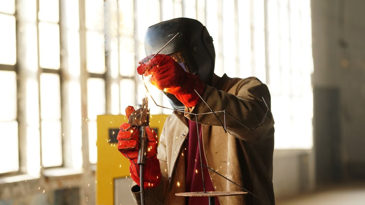
Industrial welder working in protective equipment inside a fabrication workshop
3G
The number is the position. The letter is the weld family.“3” identifies a vertical test or production orientation; “G” identifies a groove weld. The code does not identify the joint by itself.
Photo: Aziz Er, Pexels.
Decode the pattern

Number + weld family

In familiar US designations, the number identifies position and the suffix usually distinguishes a groove weld (G) from a fillet weld (F).

Do not confuse

Joint type is separate

A T-joint can carry a fillet weld or a groove weld. “T-joint,” “2F” and a drawing symbol answer different questions.

Pipe changes everything

Rotation and pipe axis matter

1G pipe is normally rotated; 5G and 6G are fixed. A welder moves through changing local orientations around a fixed pipe.

Qualification rule

Read the adopted code

A position name does not define the complete qualification range. Construction code, process, diameter, thickness and progression can change what is qualified.

Quick Answer

What does a code such as 2G mean?

2G is a horizontal groove-weld position designation. On plate, the weld axis is essentially horizontal while the groove faces lie in a vertical plane. On pipe, 2G normally describes a fixed pipe with its axis vertical, so the groove runs horizontally around the pipe. The same label therefore needs product-form context.

The code does not tell you the base metal, welding process, joint preparation, penetration requirement, filler metal, acceptance criteria or whether the welder is qualified. Those details live in the drawing, welding symbol, WPS, qualification record and governing construction code.

01 · Joint type

How parts meet

Butt, T, lap, corner and edge describe the geometric relationship of the members before welding.

02 · Weld type

What weld is deposited

Groove, fillet, plug, slot, spot and seam describe the weld family. One joint may permit more than one weld type.

03 · Position

Orientation during welding

Flat, horizontal, vertical, overhead and fixed-pipe positions describe how gravity acts on the molten pool during production or testing.

04 · Welding symbol

What the drawing requires

The symbol communicates side, size, length, pitch, contour, extent and referenced instructions. It does not automatically state the working position.

The most useful beginner rule

Never translate a code with one word only. Read it as a sentence: product form + position + weld family + progression/rotation + governing code. “6G” becomes “a fixed inclined pipe groove-weld position under the project’s adopted qualification rules,” which is far harder to misunderstand.

Joint Geometry Atlas

Five basic joint types—and what each one really tells you.

Joint names describe the arrangement of members, not the finished weld’s guaranteed strength. Load path, section size, material, fit-up, penetration, quality, fatigue detail and the design code all matter. The diagrams below are original educational illustrations, not fabrication drawings.

same planeMembers aligned

Butt joint

Two members meet edge to edge in approximately the same plane. Commonly completed with a square or prepared groove weld.

One member intersects

T-joint

One member meets the face of another, usually near 90°. Fillet welds are common, but groove preparations may be specified for the required load path.

Members overlap

Lap joint

Two members overlap on parallel planes. Fillet welds, plug welds, slot welds or combinations can transfer load through the overlap.

Members form an L

Corner joint

Members meet at their ends to form a corner. Open, closed or flush arrangements affect access, distortion and weld selection.

Parallel adjacent edges

Edge joint

Adjacent edges of parallel or nearly parallel members are joined along the edge. It is often used on sheet, flanges or nonprimary seams.

A T-joint is not the same thing as a fillet weld

The T describes member geometry. The triangle-shaped fillet describes a weld type. A T-joint may use two fillet welds, a single-bevel groove, a double-bevel groove or another engineered detail. That is why a drawing can name the joint, show a weld symbol and still require a position designation for qualification or planning.

G and F Explained

Groove and fillet are weld families—not quality grades.

The suffix in 3G or 3F identifies the weld family used for the position test or production description. Neither letter by itself says “stronger,” “full penetration” or “easier.” The engineered joint requirement and qualified procedure decide what must be achieved.

V-groove examplepreparation + root opening + weld metalG designation

Groove weld

A groove weld is deposited in a groove between workpieces. Square, V, bevel, U, J and flare preparations change access, weld volume and fusion geometry.

  • May be specified as complete-joint-penetration or partial-joint-penetration, but the letter G alone does not decide which.
  • Preparation variables can include groove angle, root face, root opening, backing and which member receives the bevel.
  • Common on butt joints and prepared T/corner joints where the design requires a controlled effective section.
two fillet welds on a T-jointF designation

Fillet weld

A fillet weld has an approximately triangular cross-section and joins surfaces that meet at an angle, commonly on T-, lap and corner joints.

  • Size may be controlled by leg dimension, effective throat or a code-specific requirement.
  • Minimal edge preparation can reduce fabrication time, but access, fit-up, root fusion and distortion still need control.
  • One-sided and two-sided details carry load differently; the drawing and design calculation govern.
QuestionGroove weld (G)Fillet weld (F)Planning implication
Typical joint contextButt joints; prepared T- and corner jointsT-, lap and corner jointsJoint type does not force one weld family; read the drawing detail.
PreparationMay require beveling, root face, root opening or backingOften little edge preparationPreparation cost must be balanced against deposition volume, access and performance.
Penetration statementCan be CJP or PJP when specifiedControlled primarily through size/effective throat and fusionNever translate G as “full penetration.”
Position suffix1G, 2G, 3G, 4G; pipe 1G/2G/5G/6G1F, 2F, 3F, 4F and product-specific fillet positionsPosition names describe orientation, not the accepted weld dimensions.
QualificationRange depends on code, test coupon and variablesMay require separate fillet qualification or be covered under stated rulesCheck the construction code and qualification record instead of assuming transfer.
Plate Position Map

1G to 4G: how gravity changes the weld pool.

These diagrams show the familiar US groove-weld position sequence for plate. Fillet positions use the F suffix and have their own workpiece orientation. Actual angular limits and qualification ranges belong to the governing standard—not to a simplified classroom sketch.

gravity ↓1G · FLAT GROOVE

Face upward

The weld is made from the upper side with the weld face approximately horizontal. Gravity generally helps retain the pool, allowing relatively stable bead placement.

Watch: excessive heat can still create burn-through, undercut or a wide fluid pool.

gravity ↓2G · HORIZONTAL GROOVE

Axis horizontal, face vertical

The weld axis is horizontal while the groove face is essentially vertical. The upper side can undercut and the lower side can receive excess metal if heat and angle are poorly controlled.

Watch: sag, unequal fusion and an overly convex lower toe.

travel ↑ example3G · VERTICAL GROOVE

Axis vertical

The weld progresses vertically. Vertical-up and vertical-down are not interchangeable technique notes; process, electrode classification, thickness and WPS determine the permitted progression.

Watch: pool sag, trapped slag, sidewall fusion and heat accumulation.

operator below4G · OVERHEAD GROOVE

Weld made from below

The weld face is on the underside of the joint. The pool must be kept controlled while heat, spatter and molten metal are above the operator.

Watch: excessive pool volume, poor tie-in, falling hot metal and restricted visibility.

Fillet codes follow the same learning logic but different joint geometry

1F is flat fillet, 2F horizontal fillet, 3F vertical fillet and 4F overhead fillet. Do not draw a direct picture of a groove coupon and simply change G to F; the orientation of the member surfaces and the fillet face determines the fillet position.

Welder producing bright sparks in a dark fabrication workshop
Photo: Ben Spray, Unsplash. Image illustrates positional welding conditions; it is not a test-position diagram.
Pipe Position Map

Rotation and pipe axis are part of the designation.

Pipe welding positions cannot be understood from “flat, horizontal, vertical, overhead” alone. You must know whether the pipe rotates, whether it is fixed and where its axis points. On a fixed pipe, the local weld orientation changes continuously as the welder moves around the circumference.

1G
Pipe axis horizontal; pipe rotatesThe weld is maintained near the top as the pipe turns. It is useful for production with rollers or a positioner, but it does not reproduce fixed-pipe access.
2G
Pipe axis vertical; pipe fixedThe groove travels horizontally around the circumference. Control of the upper and lower groove faces resembles a continuous horizontal condition.
5G
Pipe axis horizontal; pipe fixedThe operator transitions through flat, vertical and overhead regions around the pipe. Clock-position language helps teams plan roots, stops and starts.
6G
Pipe inclined, commonly about 45°; pipe fixedThe changing orientation and restricted body/torch access make it a demanding qualification configuration. It does not eliminate the need to check the exact code-qualified range.
6GR
Restricted 6G configurationThe R means restricted, not root. A ring, plate or other obstruction limits access to simulate demanding production conditions. The exact test arrangement is code-specific.
Why “passing 6G qualifies everything” is too broad

A 6G test can qualify a broad range in some codes and is highly valued because the weld includes changing orientations. But process, transfer mode, progression, backing, base-metal grouping, filler classification, thickness, pipe diameter and the adopted qualification standard can limit the range. Read the WPQ/WQTR rather than treating 6G as a universal license.

Designation Systems

AWS/ASME numbers and ISO letters describe similar geometry in different languages.

ISO 6947:2019 defines welding positions for production and testing and includes an informative comparison with US designations. The systems can be compared for orientation, but they should not be treated as automatic certification equivalents.

US designation family

1G, 2G, 3G, 4G, 5G, 6G

AWS and ASME documents use familiar number-plus-letter position labels. AWS A3.0 establishes standard welding terminology; construction and qualification standards then apply their own rules.

  • G means groove-weld position; F means fillet-weld position.
  • The same number can describe plate or pipe differently, so product form must be stated.
  • ASME Section IX treats welding position among qualification variables; AWS structural codes have their own test and range provisions.
International position family

PA, PB, PC, PD, PE, PF, PG

ISO 6947 identifies positions through letters tied to weld-axis slope and weld-face rotation. Fixed-pipe combination positions add designations such as H-L045 or J-L045.

  • PA covers flat position contexts; PC is horizontal butt welding.
  • PF identifies vertical-up progression; PG vertical-down progression.
  • H-L045 is an inclined fixed-pipe butt-welding position with upward progression; project documents must define the applicable edition and details.
Working descriptionCommon US labelCommon ISO labelImportant limitation
Flat butt/groove context1GPAComparison is descriptive; qualification equivalence must be established by the governing code.
Horizontal butt/groove on plate2GPCPB is commonly a horizontal-vertical fillet position, so do not map “2” to one ISO letter without weld type.
Vertical-up butt/groove3G uphill / upward progressionPFProgression is an essential planning and sometimes qualification detail.
Vertical-down butt/groove3G downhill / downward progressionPGA WPS qualified for upward progression may not authorize downward progression, and vice versa.
Overhead butt/groove4GPEPD commonly describes an overhead-horizontal fillet position, not the same weld family.
Fixed inclined pipe, upward progression6G contextH-L045US and ISO definitions use different designation structures and angular limits.
Use the standard named in the contract

Do not convert an ISO-qualified welder to an AWS/ASME designation—or the reverse—using only this table. Confirm the construction code, qualification standard, edition, product form, process and acceptance route. ISO itself describes Annex B as a comparison; it does not turn two independent qualification systems into one credential.

Interactive Planning Aid

Decode a welding position.

Select a designation family and code. The result gives a practical starting interpretation, not a substitute for the applicable standard, WPS or qualification record.

Planning interpretation

1G · Flat groove weld

A groove weld made in the flat position. On plate, the weld face is upward; on pipe, 1G normally means the horizontal pipe rotates so welding remains near the top.

Weld familyGroove weld
Work orientationFlat; confirm plate or rotating pipe
Primary planning issueProduct form and rotation must be stated
Do not assumeThat 1G defines penetration, process or qualification range

Always confirm the exact angular limits, test arrangement and qualification range in the project’s adopted standard and current records.

Why Position Changes the Weld

Gravity is only the first variable.

Position affects molten-pool support, heat placement, travel technique, slag behavior, accessibility and operator visibility. Good planning translates the designation into a qualified method rather than copying flat-position settings.

Molten-pool size and travel speed

A large, fluid pool may be manageable in the flat position but sag in horizontal or vertical welding and detach in overhead welding. Positional work often uses a smaller pool, controlled heat input, deliberate travel and bead sequencing. The permitted adjustment depends on process and WPS; “turn the amperage down” is not a complete procedure.

Torch or electrode angle

The angle has to place energy at both fusion faces while resisting gravitational drift. In 2G, the upper groove face may need enough energy to prevent lack of fusion while the lower edge must not collect excessive metal. In a T-joint fillet, work angle and travel angle influence leg balance and root fusion.

Vertical progression

Vertical-up is commonly selected for controlled sidewall fusion and thicker sections, while vertical-down can provide speed and lower heat input in approved applications. Those are tendencies, not universal rules. Electrode classification, transfer mode, material, thickness, service and code determine whether a progression is permitted.

Slag and shielding

With slag-producing processes, the operator must prevent slag from running ahead of the pool or becoming trapped between passes. Gas-shielded processes must maintain coverage despite torch angle, drafts and access constraints. On pipe, every clock position changes how gravity acts on slag, filler and shielding flow.

Fit-up and access

A joint can be geometrically qualified but practically unweldable if the torch, gun, filler wire, purge hardware or inspection probe cannot reach it. Fixtures, backing, root gaps, tacks and adjacent members should be reviewed before the chosen position is released for production.

Inspection and acceptance

Position does not change the design requirement, but it may change defect risk. Horizontal and overhead work can increase concern for undercut, overlap and incomplete fusion; vertical multipass work can trap slag; fixed pipe introduces starts, stops and changing access. Inspection planning should target the risks of the actual joint and process.

Laser welding uses the same geometry language

Laser welding is often automated or performed with a handheld head, so fixtures and positioners may place the seam in a favorable orientation. Even then, the joint type, seam orientation, gap, focal position, beam incidence, wobble pattern, filler delivery and shielding remain separate inputs. A 1G/2G-style position label does not qualify a laser parameter set.

Welder controlling a bright arc and sparks on metal in a workshop
Production Reality

The code names the orientation. The WPS controls the work.

A position designation is a concise geometric label. It cannot tell the welder amperage, voltage, wire feed, travel speed, shielding flow, preheat, interpass temperature, filler classification, pass sequence or acceptance criteria. Those instructions belong in an approved welding procedure and controlled job package.

Before production, connect five records: the drawing and welding symbol, joint detail, applicable WPS, welder/operator qualification, and inspection plan. If any one uses a different position, progression, process or product form, stop and resolve the mismatch.

Photo: Georgia Mashford, Unsplash.
Qualification vs Production

A test position and a production position are related—but not identical decisions.

Welder performance qualification demonstrates ability under prescribed rules. A WPS establishes how production welding is performed within a qualified range. The position code appears in both conversations, but it serves different records.

Start with the governing construction code

AWS D1.1, ASME BPVC Section IX, API 1104, ISO 9606-1 and other systems organize qualification differently. The contract or construction standard decides which qualification route is acceptable. A certificate from another scheme may be useful evidence, but it is not automatically transferable.

Separate procedure qualification from welder qualification

A procedure qualification record supports the technical range of the welding procedure; a welder performance qualification record documents the individual’s demonstrated ability. Position, process, progression and product form can affect both, but the applicable variables and ranges are not the same.

Read “actual value” and “range qualified”

A good qualification record does more than say “6G.” It identifies the process, test coupon, pipe or plate, diameter, thickness, backing, filler and other variables, then states the production range allowed by the code. That range—not the nickname of the test—is the usable authorization.

Confirm continuity and employer responsibility

Many qualification systems require continuity records and assign responsibilities to the manufacturer, contractor or employer. A welder who passed a test years ago may still need documented continuity, organizational transfer or project-specific approval. Check current records before assigning work.

Do not use a comparison chart as a conversion certificate

An ISO PA result and a US 1G label may describe comparable orientation, but the tests can differ in coupon, process, examination, acceptance and qualified range. Translate geometry for communication; qualify personnel and procedures under the required standard.

Document-control checkpoint

Record the standard and edition, drawing revision, WPS revision, actual production position, progression, welder ID, qualification range and inspection route. Position terminology is useful only when every party is using the same reference.

Worked Planning Examples

Three jobs, three different designation questions.

These examples show how joint type, weld type and position combine. They are planning illustrations only; final weld sizing, procedure and qualification must come from the engineered documents.

Structural bracket

T-joint with a 2F fillet weld

A vertical plate meets a horizontal base plate. The joint is a T-joint; the triangular weld is a fillet; the working orientation may be 2F horizontal fillet. Verify whether one or both sides are welded, leg/effective-throat size, length, access and distortion sequence.

Vertical plate seam

Butt joint with a 3G groove weld

Two plates meet edge to edge and the weld axis is vertical. The joint is a butt joint; the preparation may be V or bevel; the position is 3G. The WPS must state upward or downward progression, root method, backing, pass sequence and allowed parameters.

Process pipe

Fixed horizontal pipe in 5G

The pipe cannot rotate and its axis is horizontal. The butt joint receives a groove weld while the welder moves through top, side and bottom regions. Plan root access, purge, clock-position sequence, tie-ins, supports, heat control and a qualification range that covers the pipe diameter and wall.

Pre-Weld Checklist

Translate the designation into a controlled job.

A short code is useful only when it drives the correct engineering, qualification, fit-up, safety and inspection actions.

01 · Standard

Name the system and edition

Confirm AWS, ASME, API, ISO or customer rules. Avoid mixing code labels from one system with qualification assumptions from another.

02 · Product form

State plate, pipe or tube

The same number can represent different physical orientation on plate and pipe. Include pipe axis and whether rotation is permitted.

03 · Joint

Identify member geometry

Mark the butt, T, lap, corner or edge joint and verify which member receives any bevel or preparation.

04 · Weld

Read G, F and the drawing symbol

Confirm groove/fillet family, size, penetration requirement, side, length, pitch, contour and referenced detail.

05 · Procedure

Release a position-qualified WPS

Check process, progression, backing, filler, base-metal group, thickness, preheat, parameters and technique.

06 · Personnel

Verify actual qualification range

Review the welder/operator record, continuity, process, product form, diameter, thickness and position range.

07 · Access

Dry-run torch and body position

Check fixtures, reach, visibility, cables, filler access, purge hardware, positioner limits and inspection access.

08 · Safety

Assess the real work orientation

Overhead and restricted work can increase falling-metal, fume, posture, fire and egress risks. Apply the site hot-work program.

09 · Inspection

Target position-specific risks

Plan fit-up, in-process, visual and NDE hold points for likely fusion, slag, profile, undercut and tie-in concerns.

Frequently Asked Questions

Welding position and joint codes, answered clearly.

Short answers for training, drawing review, qualification planning and the shop-floor briefing.

What do the number and letter mean in 3G?

The number 3 identifies the vertical position in the familiar US designation family. The letter G identifies a groove weld. On plate, 3G is a vertical groove-weld position. The code does not specify upward/downward progression, process, penetration or qualification range by itself.

What is the difference between 3G and 3F?

Both refer to vertical-position contexts, but 3G is a groove-weld position and 3F is a fillet-weld position. The coupon geometry, technique and qualification rules differ. Do not assume a 3G test automatically covers every 3F production requirement without checking the governing code.

Does G mean a butt joint?

No. G means groove weld. Groove welds are common on butt joints, but they can also be used on prepared T- or corner joints. Butt describes how the members meet; groove describes the weld deposited in the prepared opening.

Does F mean a T-joint?

No. F means fillet-weld position. Fillet welds are common on T-, lap and corner joints. The letter does not identify the member arrangement or whether one or both sides are welded.

What is the easiest welding position?

Flat welding is usually the easiest starting position because gravity supports the molten pool, but “easiest” still depends on process, joint access, material, thickness and required quality. A rotating 1G pipe setup can be productive, while a complex flat joint can still be difficult.

Why is 6G considered difficult?

In 6G, the pipe is fixed on an inclined axis, commonly around 45 degrees, so the welder moves through continuously changing local orientations while access and body position are constrained. It combines many of the control challenges found in flat, vertical, horizontal and overhead regions.

What does the R mean in 6GR?

R means restricted. The test includes a restriction ring, plate or similar obstruction that limits access. It does not mean root. The exact geometry and qualified range depend on the applicable code or test specification.

Is 5G a vertical weld?

5G is a fixed pipe position with the pipe axis horizontal. As the welder travels around the circumference, the local weld passes through flat, vertical and overhead regions. Calling the entire weld simply “vertical” misses most of the position.

What is the ISO equivalent of 3G?

For descriptive comparison, PF corresponds to vertical-up butt welding and PG to vertical-down butt welding. A generic 3G label is incomplete without progression, and the comparison does not automatically transfer qualifications between AWS/ASME and ISO systems.

What is the ISO equivalent of 6G?

H-L045 is commonly compared with a fixed inclined pipe butt-welding position using upward progression; J-L045 is associated with downward progression. Confirm ISO 6947 and the project qualification standard because the notation and angular limits are not interchangeable with a simple 6G nickname.

Does passing 6G qualify a welder for all positions?

Not universally. A 6G test may qualify a broad positional range under a particular code, but process, progression, backing, pipe diameter, deposited thickness, material and other variables can restrict production work. Use the stated range on the current qualification record.

Can the welding position be changed with a positioner?

Often yes, if the drawing, WPS, equipment and production plan permit rotation. A positioner can keep the weld near a flat or favorable orientation, improve ergonomics and support automation. The resulting production position and operator qualification still need to comply with the applicable rules.

Does a welding symbol show the position?

Usually not by itself. The welding symbol describes the required weld and its location on the joint. The assembly orientation, shop drawing, fixture, WPS or process plan establishes the actual welding position. A field-weld flag, all-around mark or contour symbol should not be mistaken for a position code.

Can the same WPS be used in every position?

Only when its qualified range and written limitations cover the intended position, progression, process and joint. Some consumables and transfer modes have limited positional capability. Confirm the WPS and supporting qualification record rather than adapting settings informally.

From Code to Production

Have a joint drawing but no proven welding route?

Send Oceanplayer the material, thickness, joint type, position, fit-up range and target output. We can help identify a practical laser welding direction and the samples needed before equipment selection.