

What Is Laser Marking
and How Does It Work?
Laser marking uses a focused beam of light to change a surface and create text, logos, serial numbers or machine-readable codes. A marking machine coordinates the laser, optics and software to place that pattern on the part. The result may be a color change, a changed surface texture or an engraved recess—not every laser mark removes material.
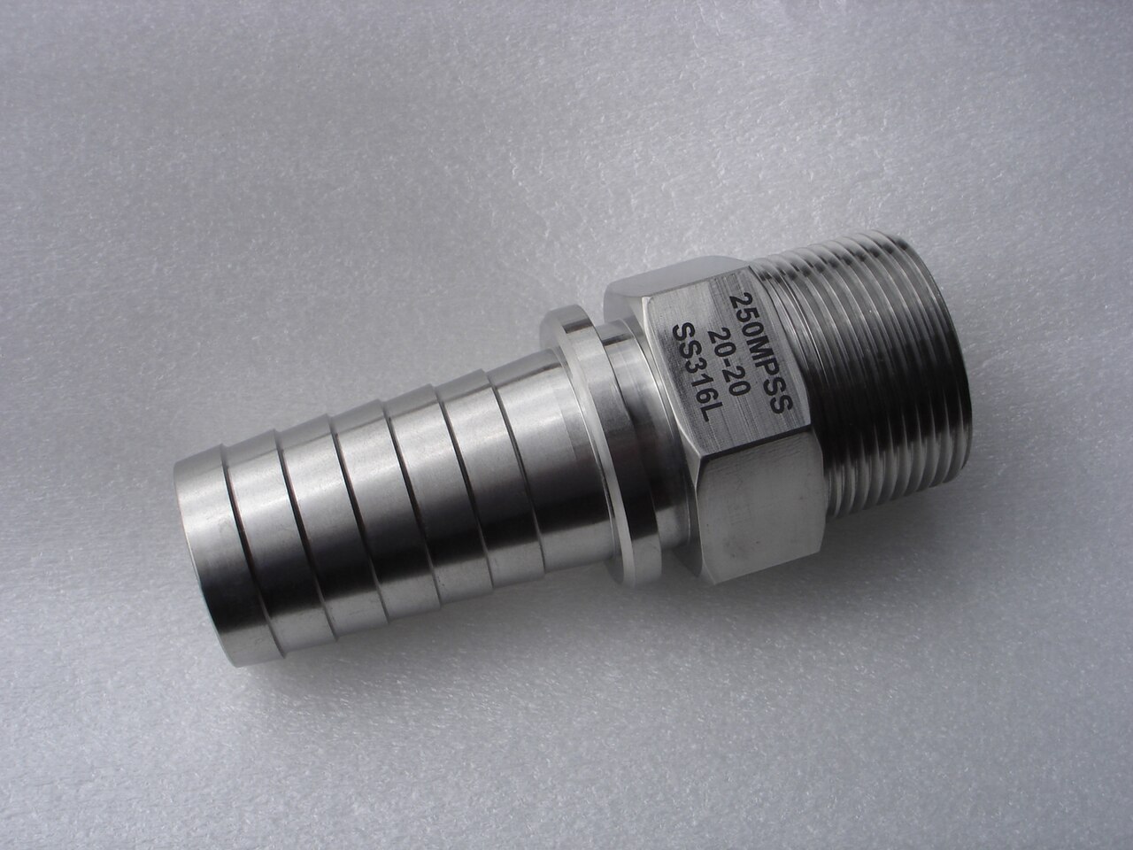
Laser-engraved 316L component photographed by Ted Lariviere, public domain. An example of an engraved result, not an Oceanplayer Laser production test.
How does a laser marking machine work?
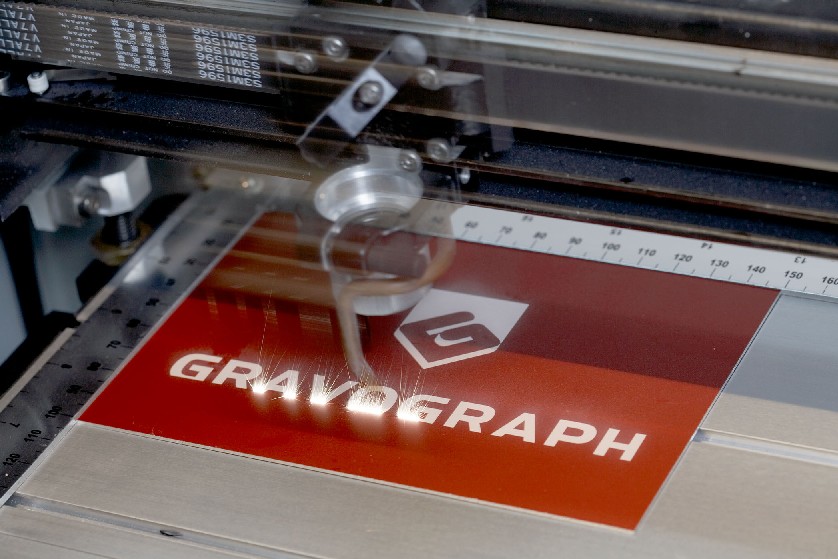
The machine turns a digital pattern into a controlled path of laser exposure. Where the material absorbs enough energy, its surface changes. The part stays in one position in many marking systems; the beam moves across it.
A common industrial design uses two small, motor-driven mirrors called galvanometers, or galvos. One steers the beam in each direction across the marking field. A focusing lens concentrates it on the workpiece. The laser controller coordinates beam movement with laser firing. [1]

- Prepare the pattern and its data.Software defines the text, artwork, filled areas and code content. For serial numbers, the data source must supply the right value for each part; a sharp mark can still contain the wrong number.
- Locate the part and establish focus.A fixture holds the marking surface at the intended height and orientation. A camera or sensor may assist positioning. Focus is not simply “close enough”: height variation can change the spot and the mark.
- Apply the selected laser recipe.The source delivers the specified output while the scanner follows the pattern. On a pulsed system, power, repetition rate and pulse duration influence how energy reaches the surface.
- Trace outlines or fill an area.The beam may draw a line once, fill a shape with closely spaced scan lines, or repeat passes. These choices affect appearance and processing time.
- Inspect the finished mark.Check the content, position and surface result. If the mark is a code, read or verify it using the method required for the application before releasing the part.
Not all machines use this same layout. Some move a head on a gantry; others add a rotary axis, conveyor tracking or focus control for curved and stepped parts. A flat-field marking area does not by itself prove that a machine can keep a curved surface in focus.
Laser marking vs engraving vs etching: what is the difference?
Laser marking is the broad term; engraving is one way to make a mark. The word “etching” is used less consistently. When discussing a job, describe the required surface result instead of relying on the process name alone.
| Term | What it normally describes | What the sample should prove |
|---|---|---|
| Laser marking | A visible or readable pattern made by changing the material or a surface layer. | Required contrast, location and readability, with an acceptable effect on the part. |
| Laser engraving | Material removal that leaves a recessed pattern. | Depth, edge quality, debris control and the effect on the remaining section. |
| Laser etching | Often a shallow surface-texturing or shallow-removal process; terminology varies between suppliers. | An agreed depth or surface profile. Do not assume a universal depth limit from the word “etching.” |
On smaller screens, swipe the table horizontally to view every column.
For example, a smooth dark identification mark and a recessed identification number may serve different needs. If cleaning access, sealing, fatigue or appearance matters, specify what surface change is allowed before selecting the process.
How does the laser change a metal or plastic surface?
The same visible color can come from different physical changes. That matters because a mark that looks right immediately may behave differently during cleaning, abrasion or later processing.
Metals: oxidation, surface texture or removal
Laser exposure can create a contrasting oxide layer, remelt the surface or remove material. These routes do not produce the same surface condition. For metal laser marking, distinguish a contrast requirement from a depth requirement; “make it darker” is not a complete specification. [1]
Plastics: color change, foaming or carbonization
A polymer or its colorants may change color under laser exposure. Foaming can create light-scattering cells and a lighter mark on dark plastic. Carbonization can create a darker mark on a lighter plastic. The actual response depends on the formulation and the laser, not just the resin name. [2]
Coated parts: expose a contrasting layer
Removing a top layer can reveal a different color underneath. One application is a backlit control button: the symbol must transmit light while the surrounding coating stays intact. This is a layer-removal task, not a request to engrave deeply into the whole part. [2]
Which laser types are used for marking?
Fiber, UV and CO₂ lasers are common starting points, but they are not interchangeable. The material must absorb the selected wavelength in a useful way. Pulse behavior and the required finish then narrow the choice.
| Source | Common applications to evaluate | What still needs a sample test |
|---|---|---|
| Pulsed fiber Typically about 1,064 nm | Metal identification and engraving; some plastics and coated surfaces. | Contrast, depth and heat effects on the exact grade, finish or formulation. |
| UV Commonly 355 nm | Fine marks on suitable plastics and other applications where shorter wavelengths are useful. | Material response, edge quality and any thermal or surface damage. “UV” does not mean damage-free. |
| CO₂ Often about 10.6 µm | Organic materials such as wood and paper, and suitable plastics or glass. | Readable contrast and texture. Do not assume the same machine will directly mark bare metals in the same way. |
Wavelengths shown are common examples, not the only wavelengths available in each source family. [1] [2] [3]
Green lasers and picosecond or femtosecond systems also serve specialized marking tasks. Wavelength and pulse duration describe different properties: a shorter pulse is not automatically a shorter wavelength.
Is MOPA different from a fiber laser?
A MOPA fiber marker is still a fiber laser marker. MOPA means master oscillator power amplifier, an arrangement that generates a signal and then amplifies it. In many industrial marking systems, it allows more control over pulse duration and repetition rate than a conventional Q-switched design. [3]
That flexibility can help tune a difficult mark, but it does not guarantee color marking, less heat or faster output on every material. Compare the actual source settings and sample result—not “MOPA vs fiber” as though they were mutually exclusive categories.
For a more detailed source comparison, see fiber vs UV laser marking. For equipment built around adjustable-pulse fiber sources, see MOPA laser marking machines.
Why does the exact material and finish matter?
“Aluminum” does not tell the whole story. Bare, anodized and painted aluminum present different surfaces to the beam. Likewise, two parts labeled with the same plastic family can contain different pigments or additives and produce different marks.
Illustrative example: a black molded housing marks well, then a white version gives weak contrast using the same recipe. Before increasing power, check whether the formulation and absorption changed. The first successful sample did not validate both colors.
Test representative production parts, including the finish and color variants you will actually sell. A polished demonstration coupon is not a substitute for a textured, curved or coated production part.
Which settings affect laser marking quality and speed?
No single setting controls the whole result. Keep the material and desired finish fixed while evaluating how these settings work together:
- Power and pulse behavior: average power, pulse energy, pulse duration and repetition rate are related but are not the same quantity.
- Scan speed: how quickly the spot travels across the surface. A faster scan changes the exposure delivered along a line.
- Hatch spacing and passes: the gap between fill lines and the number of repetitions. Tighter spacing or more passes adds work; it does not always improve the finish.
- Focus and field setup: spot size, working height and the usable marking field must suit the smallest feature and the part geometry.
A simple pulse-spacing example
Consider a straight line scanned at a constant 1,000 mm/s with uniformly spaced pulses at 50 kHz, or 50,000 pulses per second. The distance between pulse centers is:
Pulse spacing = scan speed ÷ pulse rate
1,000 ÷ 50,000 = 0.020 mm = 20 µm
At 2,000 mm/s with the same pulse rate, spacing becomes 40 µm. This is a calculated illustration, not a recommended marking recipe.
The calculation does not tell you the overlap or whether the mark will be acceptable. You still need the actual spot size, pulse energy, surface response and scan pattern. It also assumes steady movement; corners and acceleration regions need separate attention.
Scan speed is not finished parts per hour
A production cycle includes loading, positioning, marking, checking the result and unloading. A quoted scanner speed leaves most of that out. Compare complete cycles using the same artwork, mark quality and part-handling method.
Is laser marking permanent, and can it damage a part?
A laser mark can be durable because it changes the part or its surface layer instead of adding an ordinary printed label. But durable is not the same as impossible to remove. Wear can remove a shallow mark, later finishing can cover it, and chemical exposure can change its contrast.
“Non-contact” means the marking tool does not press on the part. It does not mean that the laser leaves the material unchanged. Excessive or unsuitable exposure can remove too much material, create an unwanted heat effect or alter a coating that has a protective function.
Choose the durability test from the part’s service conditions. If a component will be washed, exposed to solvents, coated or repeatedly handled, check the mark after those operations. For corrosion-sensitive or safety-critical parts, appearance alone is not sufficient evidence of an acceptable process.
Agree what must remain acceptable: readable content, surface condition, mark depth, appearance or all of these. Then record the exposure conditions and acceptance method with the approved recipe.
How do you check a laser-marked code?
Separate three questions: Does the code contain the right data? Can the intended reader decode it? Does it meet the required symbol-quality specification? These are different checks. A successful phone scan does not answer all three.
- Check the data. Confirm the serial number or payload against the job record. Include missing-data and duplicate-number handling.
- Check reading in the real setup. Use the intended reader, working distance, part orientation and lighting. A reflective surface can look very different under a different light.
- Verify quality when the specification requires it. Use the agreed verification method and reporting conditions. ISO/IEC 29158:2025 addresses direct-part-marked symbol quality, including illumination, measurement and grading changes relative to ISO/IEC 15415. It does not give every customer the same acceptance requirement. [4]
A Data Matrix symbol is also not automatically a GS1 DataMatrix symbol. GS1 use involves specific data-encoding rules, not only the appearance of the square pattern. Confirm the required code format before testing a serial-number marking workflow. [5]
Keep records of the part variant, mark file, recipe and inspection result so a later change in material or layout can be evaluated against the same requirement.
What safety and maintenance does laser marking need?
A small marking area can still involve hazardous laser radiation. A properly engineered enclosed system may have a lower accessible-emission classification than the high-power laser inside it. Opening an enclosure for service changes the exposure situation. Do not bypass interlocks to speed up loading or troubleshooting. [6]
Assess beam access, reflections, fire risk and process-generated fumes for the actual installation. Enclosure design and extraction must suit the material and process. Protective eyewear, where required by the assessment, is not a substitute for preventing access to hazardous radiation. [6] [7]
Direct laser marking can avoid ink and printing stencils, but that does not make the complete system maintenance-free. Follow the equipment instructions for optics inspection, cooling and extraction servicing. Include filters, cleaning supplies and any application-specific marking aids in the operating-cost assessment.
How should you choose a laser marking machine?
Start with the part and the required mark, not a wattage alone. Ask a supplier to demonstrate a repeatable result on representative parts, then confirm that the complete machine can deliver it at the required production rate.
A useful sample request includes:
- The part: material grade or resin, finish, color variants, dimensions and photographs.
- The mark: artwork or code format, actual size, location, required contrast and any depth or surface restrictions.
- The workflow: batch size, complete cycle target, loading method and variable-data source.
- The proof: reader or verification requirements and the cleaning, wear or other exposures the mark must survive.
For a standalone station, focus on repeatable loading and clear work instructions. For an automated laser marking system, also define line interfaces, data transfer and what happens when marking or reading fails.
The practical choice is the combination of source, optics, fixture, software and inspection that produces the required mark reliably. Explore Oceanplayer Laser marking machines once those requirements are clear.
Technical sources
- Coherent: What is Laser Marking? — common scanner architecture, surface processes and source families.
- TRUMPF: Laser marking plastic — absorption, formulation, color changes, foaming and layer removal.
- Gravotech: How does MOPA fiber laser technology work? — source architecture and pulse-control flexibility.
- ISO/IEC 29158:2025 — direct-part-mark symbol-quality test specification, second edition.
- GS1 DataMatrix Guideline — GS1-specific encoding and application guidance; linked release 2.5.1.
- Oregon OSHA: Lasers—Safe work practices — enclosure, classification and exposure principles; September 2025 fact sheet.
- OSHA Technical Manual: Laser hazards — beam controls and process-generated airborne hazards.
- IPG Photonics: Laser Marking — process definition and comparison with traditional identification methods.