

6 Key Reasons Your Laser Fiber Gets Damaged
Laser fiber damage is usually the end of a failure chain—not a random event. The most common chains begin with mechanical strain, a contaminated connector, incorrect coupling, back-reflected process light, poor thermal management, or a head-side fault that is allowed to continue.

The six damage paths, at a glance
“Laser fiber” can mean the internal gain fiber, a fixed process fiber, or a detachable beam-delivery cable. Operators usually interact with the last two. The exact connector, cooling circuit, bend limit and service method depend on the laser model, so the machine manual remains the controlling document.
Stress can damage the glass, reinforcement, jacket or connector strain relief—even when the outside still looks acceptable.
Dust, fingerprints, condensate or residue can absorb concentrated light and turn a cleanable surface into a permanent burn.
A partially engaged or misaligned interface can send energy into the cladding or connector instead of the intended core.
Highly reflective workpieces and unstable starts can return light toward the delivery path and laser source.
Restricted flow, wrong coolant conditions or operating below dew point can create abnormal heat or moisture where neither belongs.
Damaged process optics, spatter, collision and repeated flexing can turn a local head problem into a delivery-fiber failure.
What does “laser fiber damage” actually mean?
A fiber laser source generates light in doped optical fiber, but the cable an operator sees outside the source is often the process or delivery fiber. Some systems have a field-removable QBH, QD or RQB-style interface; other systems use a fixed fiber that must not be disconnected by the user. Treating those architectures as interchangeable is a costly mistake.
Before troubleshooting, identify the laser-source model, connector type, whether the fiber is user-replaceable, the specified routing limits, the cooling method and the interlock chain. If any of those facts are unknown, pause and obtain the correct manual or service instructions.
Why a small defect becomes a high-power failure
The transmission path is efficient only when the beam remains centered and the optical surfaces remain clean. Local absorption changes optical power into heat. Misalignment can couple energy into the cladding or connector structure. Reflection from the workpiece can send energy back toward the laser. Once a microscopic spot heats, it may grow rapidly, so repeated “one more test” runs can convert a recoverable contamination issue into a damaged connector or process fiber.
Coherent’s CleanLine manual explains that even less-visible oils, condensates and dried residues can attenuate a fiber connection; at higher power, contamination at the fiber tip can burn onto the optical surface and make replacement necessary. The manual also emphasizes inspection, cleaning and re-inspection before mating fiber connections.
Technical reference: Coherent CleanLine Laser System User Manual, fiber-connection maintenance section.
The cable is more than a flexible light pipe
A high-power delivery assembly can include the optical core and cladding, mechanical reinforcement, protective jacket, interlocks, cooling features, a mode stripper and precision connector hardware. Each layer manages a different failure mode.
- Glass and coatings guide the intended optical mode and must remain below their mechanical and thermal limits.
- Reinforcement and jacket protect the glass from pull, crush, torsion and repetitive motion.
- Connector and quartz block position the beam and manage high optical intensity at the interface.
- Cooling and mode stripping remove heat and unwanted light that would otherwise accumulate locally.
- Interlocks and sensors prevent emission when the interface is open or abnormal conditions are detected.
Because designs differ, never copy a bend-radius value, coolant temperature or cleaning chemistry from an unrelated laser. Model-specific instructions are not optional setup details; they define the safe operating envelope.
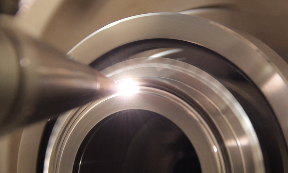
Image and architecture reference: Coherent — Laser Beam Delivery Components.
Tight bends, pulling, twisting and crushing
The fiber may look flexible, but it is not an ordinary electrical cable. A bend below the specified radius increases mechanical stress and can also change optical behavior. Pulling from the connector, rolling a cart over the jacket, pinching it under a machine panel, twisting it during head movement or letting a coil rub repeatedly against a sharp edge can damage different layers of the assembly.
A single severe event can crack or kink the fiber. Repeated lower-level motion can create fatigue near strain-relief points, cable carriers and robot dress packs. This is why a routing path that looks safe while the machine is stationary must also be checked at every axis extreme and throughout the complete program.
Keep weight off the connector and protect the jacket from sharp sheet-metal edges.
Look for tension, torsion, rubbing and radius reduction across the complete cycle.
Cap the connector and store the assembly where it cannot be stepped on, crushed or contaminated.
Dust, fingerprints, vapor film and dried residue
Connector contamination is one of the most preventable high-consequence failures. A particle does not have to cover the entire core to matter. At a high-intensity optical surface, local absorption can create a hot spot, permanently mark the end face and seed further damage.
Visible dust is only part of the risk. Fingerprint oil, aerosol, moisture, dried solvent residue and condensate may be difficult to see without the correct video inspection system. A cap can also recontaminate a cleaned connector if the cap itself has been exposed to the shop.

Connector cleanliness is an optical requirement
This communications connector is not an industrial QBH or QD interface, but it shows the precision surfaces involved in fiber coupling. Industrial high-power interfaces require their own approved inspection adapter, cleaning tools and procedure.
Photo: Adamantios, Wikimedia Commons, CC BY-SA 3.0.
A partially seated, wrong or misaligned interface
High-power coupling depends on precise mechanical seating and optical alignment. If the connector is rotated incorrectly, incompletely locked, inserted against contamination, cross-threaded or unsupported by its strain relief, the system may not place the beam where the receiving optics expect it.
Modern connectors often include interlocks and thermal protection, but those controls do not make forced installation safe. Never bypass an interlock to “see whether the laser will run.” Never adjust a coupler or internal alignment unless the manufacturer’s service process explicitly authorizes the procedure and provides the required measurement setup.
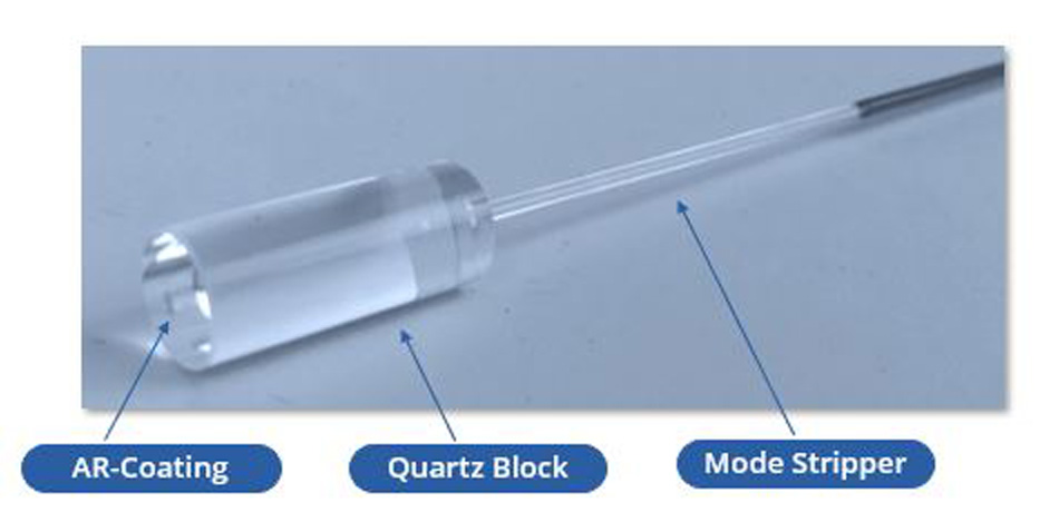
The connector manages more than alignment
High-power assemblies may use a quartz block, cooling structure and mode stripper to manage unwanted light and heat. Those protections work only when the complete interface is correctly installed and operated within specification.
Image and technical context: Coherent — Improved QBH Fiber Optic Cables.
Back reflection can turn the workpiece into a return path
Fiber lasers commonly operate near one micrometre wavelength, where metals such as copper, brass and aluminum can be challenging—especially during an unstable start, poor focus condition or shallow-angle interaction. Some of the incident energy can return through the process optics toward the delivery fiber and source.
The correct response is not a blanket ban on reflective metals. It is to use a laser with suitable back-reflection protection, a qualified parameter window, correct work angle and focus strategy, clean optics, reliable workholding and monitoring appropriate to the risk.
Reference: nLIGHT — Back-reflection Protection.
Concept diagram only. The exact return path and protection architecture depend on the laser, process head, material, geometry and operating point.
Restricted cooling, wrong conditions or condensation
High-power connectors and mode-management components may reject heat through air cooling, water cooling or conduction into the receiving assembly. Low flow, clogged filters, incorrect coolant quality, a disconnected line, wrong setpoint or blocked heat exchanger can raise local temperature. An optical loss that would normally be manageable may then become a damaging hot spot.
Cooling can also create a second hazard: condensation. If an optical or mechanical surface is cooled below the surrounding air’s dew point, moisture can form. Water on or near an optical interface is contamination, not “extra cooling.” The acceptable combination of ambient temperature, humidity, coolant temperature and warm-up time is machine-specific.
Environmental example: TRUMPF installation documentation uses a dew-point operating envelope to prevent condensation; the permissible limits depend on the machine configuration. See the TruLaser 2030 fiber pre-installation manual.
Damaged process optics, collision and ignored warning signals
The delivery fiber does not operate alone. A contaminated or cracked protective window, overheated collimating optics, nozzle collision, poor head alignment, spatter intrusion or failed seal can distort the beam path and increase absorption or reflected energy. On a moving system, the same incident may also pull or twist the cable.
The practical mistake is diagnosing each alarm in isolation. For example, a head collision followed by weak output, connector temperature rise and repeated reflection alarms should be treated as one event chain. Replacing only the nozzle and continuing at full power may leave damaged optics or cable routing unexamined.
Do not repair the last visible symptom only
Workpiece height, stand-off, focus or spatter condition changes suddenly.
Transmission drops and heat or reflected power increases.
Temperature, reflection or power alarms appear.
Correct the initiating event before replacing downstream parts.
What the symptom suggests—and when to stop
These observations help structure a diagnosis. They do not replace the laser source’s fault codes, service manual or a qualified technician’s measurements.
| Observed symptom | Possible fiber-related path | Other likely causes to check | Immediate response |
|---|---|---|---|
| Output changes with axis or robot position | Excess bend, torsion, pinch, fatigued strain relief or damaged cable carrier route. | Loose electrical cable, head motion fault, focus shift or program-dependent process condition. | Stop repetitive motion and inspect the complete route before further high-power operation. |
| Connector temperature rises abnormally | Contamination, misalignment, inadequate cooling, cladding light or back-reflected power. | Temperature sensor, cooling flow or receiving-optic fault. | Stop emission; do not disconnect a hot or energized connector. Follow the service procedure. |
| Weak or distorted beam after maintenance | Dirty or incorrectly seated interface; wrong connector orientation or damaged end face. | Protective window installed incorrectly, focus setting, lens contamination or source setting. | Return to the approved inspection and connection checklist; do not compensate with more power. |
| Back-reflection alarms on copper, brass or aluminum | Returned energy reaching the fiber/source or protection threshold. | Focus, work angle, surface condition, start strategy, process stability or unsuitable laser architecture. | Stop repeated resets; validate the material and parameter window with the laser supplier. |
| Visible kink, crush, burn, melted jacket or exposed reinforcement | Direct mechanical or thermal damage to the delivery assembly. | Collision, routing error, hot workpiece contact or cable-carrier failure. | Remove the system from service and isolate it for qualified inspection. |
| Intermittent alarm after a collision | Internal cable strain, connector shift or head-side optical damage affecting the fiber path. | Nozzle, ceramic, protective window, collimator, sensor or motion-axis damage. | Preserve event logs and inspect the full head-to-source chain before restarting production. |
Inspect without creating the next failure
The correct sequence controls laser, electrical, mechanical, coolant and gas hazards before anyone approaches an optical interface.
Record the alarm, program step, material, power, axis position, connector temperature and event history.
Use the machine’s shutdown and facility energy-control procedure. Never rely on an E-stop alone for service isolation.
Check routing, jacket, supports, connector seating, coolant lines, head collision evidence and process optics allowed for operator maintenance.
Only trained authorized personnel should open or inspect fiber interfaces with approved indirect viewing equipment and adapters.
After the cause is corrected, follow the manufacturer’s controlled restart and validation method before production power.
Never look into a fiber end or inspect it with a direct optical microscope while the system can emit.
High-power industrial fiber lasers commonly contain an embedded Class 4 source. Service access can defeat the normal enclosure that makes production operation safer. Follow the laser manufacturer, facility laser-safety officer and applicable energy-control procedure. OSHA distinguishes normal operation from maintenance and service because accessible-beam hazards can change when protective housings or connections are opened.
Safety references: OSHA Technical Manual, Laser Hazards and OSHA Control of Hazardous Energy.
A maintenance routine built around events and evidence
Calendar checks matter, but event-triggered inspection is equally important. A collision, cable reroute, connector removal, chiller alarm or new reflective material should trigger a specific response.
External condition
- Walk the visible fiber route and check supports, abrasion, pinch points and minimum clearance.
- Confirm coolant, interlock and process-head status before enabling the source.
- Review unresolved alarms from the previous shift.
- Verify the processing head has not been opened or collided without sign-off.
Connection integrity
- Use the correct shutdown and energy-isolation procedure.
- Inspect and clean only with approved tools, adapters and methods.
- Verify connector orientation, complete seating, lock, strain relief and cooling connections.
- Re-run the specified low-risk commissioning or power verification.
Process health
- Track reflection, temperature, power and cooling alarms by material and program.
- Trend protective-window life and collisions rather than treating each replacement as unrelated.
- Review robot or gantry cable motion after layout or production changes.
- Escalate repeating faults before they become permanent optical damage.
Prevent fiber damage before the machine enters production
Oceanplayer can review the material, process, laser power, motion route, work environment and expected duty cycle before recommending a cleaning or welding system. The goal is not merely to select wattage—it is to build a stable beam-delivery and process window.
- Laser source brand, model and rated power
- Cleaning, welding or cutting process and material
- Photos of the cable route, head and connector area
- Alarm codes, event history and when the symptom appears
- Cooling configuration, environment and motion duty cycle
Laser fiber damage FAQ
Short answers for operators, maintenance teams and equipment buyers.
What is the most common cause of laser fiber damage?
There is no universal single cause across all fiber-laser architectures. In field-accessible delivery systems, mechanical routing errors and contaminated connector interfaces are highly preventable causes. Process back reflection and thermal faults become more important with high power, reflective materials and unstable operating conditions.
Can a laser fiber be damaged even if the outer jacket looks normal?
Yes. The jacket may hide internal glass damage, coating stress, connector misalignment or a burned optical surface. Motion-dependent output, abnormal connector temperature, reflection alarms and performance changes after a collision deserve investigation even when the cable exterior looks intact.
How tightly can I bend a fiber laser cable?
Use the minimum bend radius or minimum bend diameter specified for the exact fiber assembly and operating condition. Values vary widely with construction, connector, power, whether the cable is moving and whether it is in storage. A number from another laser model is not a safe substitute.
Can I clean a QBH connector with alcohol?
Only if the manufacturer’s procedure for that interface permits the specified solvent, grade, tool and technique. Many procedures prefer inspection and approved dry cleaning first. Incorrect wet cleaning can redistribute contamination or leave residue. The connector must be de-energized, inspected indirectly and re-inspected after cleaning.
Can high laser power alone destroy the delivery fiber?
A correctly designed assembly can transmit its rated power when clean, aligned, cooled and operated within specification. Damage risk rises when high power is combined with contamination, poor coupling, inadequate cooling, reflected energy or a fiber not rated for the application. Do not exceed the laser and delivery assembly ratings.
Why are copper and brass harder on some fiber lasers?
These materials can reflect substantial near-infrared energy, especially before a stable process is established. The actual risk depends on wavelength, surface condition, geometry, focus, work angle, process stability and the laser’s back-reflection protection. Use a validated parameter window and suitable source architecture.
Does fluctuating assist gas directly damage the laser fiber?
Not usually as a primary mechanism. Gas instability more directly affects cut or weld quality, plume removal and process stability. It can contribute indirectly if an unstable process increases spatter, contaminates optics or changes reflected energy. Diagnose the process chain rather than labeling every gas fault as fiber damage.
Does electrostatic discharge damage the optical fiber?
ESD is mainly a risk to electronic controls, sensors and laser-diode circuitry, not the passive delivery glass itself. ESD controls may still be required during service, but they should be managed as a separate electronics-protection issue rather than presented as a common optical-fiber damage mechanism.
Can a damaged laser fiber be repaired?
It depends on the architecture and damage location. Some detachable delivery fibers can be replaced or serviced by an authorized facility; many fixed process fibers or damaged high-power end faces require factory service. Do not splice, polish or realign a high-power industrial delivery fiber using telecommunications repair methods.
When should I stop using the machine immediately?
Stop when you find a kink, crush, burn or exposed jacket; when connector or cable temperature is abnormal; when reflection or fiber alarms recur; after a collision followed by output change; when cooling is lost; or when the connector interface cannot be confirmed clean and correctly seated. Follow the machine’s safe shutdown and energy-control procedure.
Sources used to correct and expand this guide
Primary and manufacturer documentation was used for fiber cleanliness, beam delivery, reflection protection, environmental control and service safety.
- Coherent — CleanLine Laser System User Manual: contamination, inspection, cleaning and fiber-end safety.
- Coherent — Laser Beam Delivery Components: industrial delivery fibers, connectors, cooling and mode-management architecture.
- Coherent — Improved QBH Fiber Optic Cables: quartz block, mode stripper, cooling and high-power connector design.
- nLIGHT — Back-reflection Protection: returned process light and hardware isolation.
- TRUMPF — TruLaser 2030 Fiber Pre-Installation Manual: model-specific ambient and dew-point control.
- OSHA Technical Manual — Laser Hazards: distinction between operation, maintenance and service.
- OSHA — Control of Hazardous Energy: servicing and maintenance energy-control framework.