

What Is Arc Voltage, and How Does It Form?
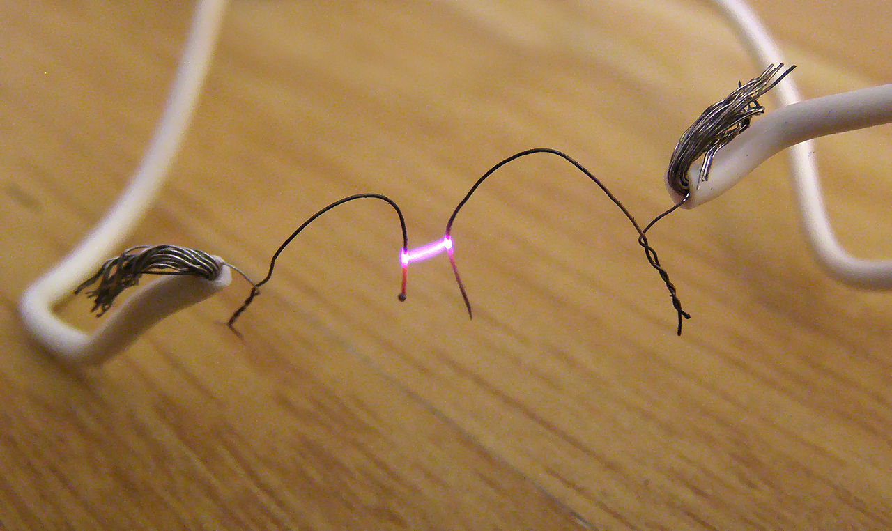
Arc voltage is the electrical potential difference across an operating electric arc. The arc carries current through a hot, ionized gas called plasma. Its voltage depends on the gap, electrodes, gas and current; a welding-machine reading may also include losses outside the arc. It is different from the open-circuit voltage present before welding current flows.
To interpret a reading, identify the process, the measurement points and whether the display shows a setting, a measured value or an arc-length correction.
Arc voltage, open-circuit voltage and input voltage
Voltage describes the potential difference between two points. The operating state and the chosen points are part of its meaning.
On small screens, scroll the table sideways to read all columns.
| Quantity | What it describes | How to interpret it |
|---|---|---|
| Arc voltage | The voltage across the conducting arc, including its electrode attachment regions. | A property of the loaded welding process. Record the sensing locations because practical readings may include other voltage drops. |
| Open-circuit voltage (OCV) | The output voltage with no welding current flowing. | It is commonly higher than the running arc voltage. Voltage-reduction functions can change the idle reading. OCV is not an input for a weld-energy calculation. |
| Terminal voltage | The voltage measured at the power-source output connections. | During welding it includes drops along the circuit between those terminals. A compensated display may show a different quantity. |
| Mains input voltage | The supply feeding the welding machine. | A label such as 110 V or 220 V describes the supply side, not the voltage across the weld arc. |
A voltage setting is also different from a measurement. A controller can command one value while a display reports a measured average or holds the last weld value. Read the display definition before comparing it with a welding procedure specification (WPS). Supply-side choices are covered in the 110 V versus 220 V welder guide.
How does an electric arc form?
An arc needs a source of electrical energy and a path that can conduct across the gap. Starting creates that path; continued current sustains it.
- The starting method creates a conducting path.In contact-start processes, the electrodes briefly touch and then separate. TIG can use a controlled lift start or high-frequency ignition that ionizes the gap without contact.
- The gas becomes plasma.Ionization frees electrons from atoms, leaving charged ions. These particles can move under an electric field, allowing current to cross gas that was initially a poor conductor.
- Electrical input maintains the hot channel.The arc exchanges energy with the electrodes, gas and surroundings. Its operating voltage follows the resulting plasma conditions and the power source's response.
A hot conducting gap does not need the same conditions as a cold gap at ignition. OCV, an added high-frequency ignition pulse and the running arc voltage are three different quantities. An arc also needs continued energy; ionization alone does not keep it burning.
See TWI's TIG equipment explanation for the distinction between HF and lift starting.

What creates the voltage drop across the arc?
The total includes two near-electrode regions and the plasma column between them. The visible gap is only part of the explanation.
The region where electrons enter the plasma from the cathode. Conditions at the electrode surface affect this localized voltage contribution.
The conducting gas between the electrode regions. Its voltage drop depends on length, composition, temperature and the current-carrying cross-section.
The region where electrons enter the anode. Its contribution depends on the electrode and the arc attachment conditions.
This is a description of the regions, not a set of fixed voltage values. In AC welding, electrode polarity changes through the cycle.
Why does a longer arc usually need more voltage?
With comparable current, gas and electrode conditions, a longer plasma column generally requires a larger voltage drop. That makes voltage useful for monitoring arc length. It does not create a universal volts-per-millimeter conversion: changing gas, current or electrode conditions changes the relationship.
An arc also behaves differently from a fixed resistor. Its conductivity and shape change as it heats and as current changes. A relationship measured in one operating range cannot be extended to every arc. NISTIR 5037, section 2.3.3, separates the arc regions from the contact and wire-extension drops in GMAW.
What does voltage control in MIG, TIG and stick welding?
Conventional MIG mainly pairs a voltage setting with wire-feed speed. TIG and stick mainly set current, with voltage responding to the arc length held by the operator or a height-control system.
Constant voltage: the wire melts to match the feed
In conventional gas metal arc welding (GMAW, often called MIG/MAG), a shorter arc causes a current increase that melts the wire faster. A longer arc reduces current, allowing the feeding wire to catch up. This helps restore arc length. Wire-feed speed strongly influences the current needed to maintain that balance.
“Constant” describes the source characteristic; the voltage still varies during starts, short circuits and other disturbances.
Constant current: voltage follows the held gap
In gas tungsten arc welding (GTAW/TIG) and shielded metal arc welding (SMAW/stick), a moderate arc-length change causes a voltage change while current changes much less. The operator therefore controls the gap directly. An increased voltage reading can reflect a longer arc without indicating a new current setting.
This relationship applies within the source's operating range. It does not mean the machine can maintain current across any gap.
Compare the control mode before comparing voltage numbers. Scroll sideways on small screens.
| Process | Read voltage alongside | Main interpretation limit |
|---|---|---|
| TIG / GTAW | Current, tungsten-to-work gap, shielding gas, DC polarity or AC program. | Voltage alone cannot isolate a height change when current, gas or the AC/pulse program also changes. |
| Stick / SMAW | Current, electrode classification, polarity and operator-held arc length. | Electrode type and polarity change the operating window. Compare readings under matching conditions. |
| Conventional MIG/MAG and flux-cored arc welding (FCAW) | Wire feed, wire type/diameter, gas, polarity, electrode extension and transfer mode. | Short-circuit transfer deliberately alternates contact and arcing. A fluctuating voltage trace is not automatically a fault. |
| Pulsed or synergic wire welding | Exact machine program and the meaning of its voltage or arc-length control. | A trim or correction number may not be volts. Do not transfer the number to another machine or program. |

There is no single “normal welding voltage”
A range without the process, consumable and operating conditions can be misleading. Use the machine program and electrode data for the actual joint. For wire-and-voltage setup, the MIG wire-speed and voltage guide covers the relationship in more detail.
As a specific display example, Miller's OM-285184B manual, section 7-11, describes a pulsed-MIG arc-length correction centered on 0.0. That zero is a control reference, not zero arc voltage or a zero-length gap.
Why do the machine display and an external meter disagree?
First check whether they measure the same points, over the same interval, using the same averaging method. A difference can be caused by circuit losses, display compensation or waveform processing.
A near-torch reading still includes more than plasma
In wire welding, a voltage measured between the contact tip and workpiece includes the arc plus the electrode-extension drop and contact effects. Moving the sensing point from the machine toward the torch removes some cable losses; it does not remove the energized wire between the tip and the arc.
Electrode extension runs from the contact tip to the melting end of the wire. Arc length runs from that end to the pool. For the simplified geometry shown, their sum is the contact-tip-to-work distance (CTWD). Nozzle-based “stickout” is a different dimension when the contact tip is recessed.
In a steady resistive approximation, the extra drop between two sensing locations is I × R. Pulsed circuits also have dynamic effects, so this is not a complete instantaneous model.
Calculated illustration: at 200 A, an assumed extra circuit resistance of 0.010 Ω produces a 2.0 V drop and 400 W of resistive heating in that part of the circuit. These are hypothetical inputs, not a normal resistance target. A display difference alone does not identify where a loss occurs.
Distinguish commanded, measured and held values; check remote sensing and compensation. Fronius's circuit-resistance documentation gives an example where output-jack voltage exceeds the controlled near-arc value by the hosepack drop.
Follow the instrument and welder instructions for the process, input limits and isolation. TWI specifically warns that TIG ignition voltage can damage instruments that are not designed for arc monitoring.
Use the same steady-welding interval for both instruments. Capture starts, crater filling and stops separately when those events are being investigated. Record sensing points, CTWD, program, consumable, gas, current and travel speed.
Mean, root mean square (RMS) and instantaneous voltage describe different things. A true-RMS label alone does not provide mean electrical power. For varying waveforms, use synchronized voltage/current acquisition with the bandwidth and calculation method required by the procedure.
Measurement safety: welding circuits can cause fatal shock. Isolate the source before connecting or changing leads; electrical testing belongs with competent personnel using an approved setup. Stop if insulation, connectors or equipment are damaged. See the SafeWork NSW arc-welding alert.
How do voltage and current become energy per weld length?
Electrical power is voltage multiplied by current at the same instant. Energy per unit length also depends on travel speed. Higher voltage by itself does not establish higher heat input or deeper fusion.
Varying waveform: Pmean = mean[v(t) × i(t)]
Energy (kJ/mm) = 60 × Pmean (kW) ÷ speed (mm/min)
The voltage sensing boundary remains part of the result. Values measured at the machine can include losses outside the intended weld region.
For pulsed, AC or short-circuit waveforms, use measured mean instantaneous power. Separate average voltage and current readings are not enough.
Enter positive finite values in the stated units. Blank, zero or invalid entries clear the result. Initial values are an illustrative example, not recommended settings.
Electrical energy estimate
- Electrical power
- 4.80 kW
- Energy per weld length
- 0.960 kJ/mm
Stable DC example: 4.80 kW and 0.960 kJ/mm.
No efficiency factor is applied. The result does not determine a WPS limit, weld acceptance or arc-flash protection.
Worked example: stable DC
Assume constant 24 V and 200 A at a defined measurement boundary. Power is 4.8 kW. At 300 mm/min, or 5 mm/s, energy per length is 4.8 ÷ 5 = 0.960 kJ/mm. Doubling speed while keeping power unchanged halves this value. This arithmetic does not predict the final weld shape.
Why multiplying separate averages can fail
Consider a hypothetical two-level waveform: half the time at 30 V and 300 A, half at 20 V and 100 A. This is an arithmetic illustration, not a welding program.
Mean power = (30 × 300 + 20 × 100) ÷ 2 = 5.5 kW
Mean V × mean I = 25 × 200 = 5.0 kW
At 300 mm/min, the corresponding energies are 1.10 and 1.00 kJ/mm. The difference comes from voltage and current changing together. Multiplying RMS readings is not a general substitute for averaging their instantaneous product either.
Arc energy and heat input are not always named the same way
TWI distinguishes arc energy from heat input calculated with a process-efficiency factor: HI = η × AE. It also notes that some American codes call uncorrected arc energy “heat input.” Use the definition and method required by the applicable procedure. The welding heat-input calculator covers efficiency and unit conversions.
What should you check when voltage seems wrong?
Use the reading to narrow the investigation. Confirm the measurement and operating mode before changing a setpoint.
Scroll sideways on small screens to reach the investigation column.
| Observation | Possible explanation | What to check next |
|---|---|---|
| Display and meter disagree | Different sensing points, cable losses, compensation, averaging or a held display. | Compare the same weld interval and quantity. Have the circuit checked before assuming the controller is defective. |
| Conventional MIG stubs or makes a convex bead | Voltage may be low relative to wire feed. Travel, feeding and joint access can produce similar symptoms. | Restore the specified wire, gas, polarity and CTWD; inspect feeding and connections. Then adjust within the applicable setup guidance. |
| Conventional MIG has poor arc control | Excessive voltage can contribute to an erratic arc and turbulent pool. | Check wire-feed balance and intended transfer mode. Change one variable at a time and compare the actual joint result. |
| TIG or stick voltage rises | A longer arc at roughly the same current is one explanation. | Check electrode-to-work distance and technique, then gas/electrode condition and sensing points. |
| Pulsed or short-circuit voltage fluctuates | The waveform may be behaving normally, or a mechanical/electrical disturbance may be present. | Compare against the same program's expected behavior. One average value cannot distinguish these cases. |
Miller's solid-wire MIG guidance describes the high- and low-voltage symptoms above. They are clues, not unique diagnoses. Surface appearance and a stable voltage trace cannot establish internal fusion or mechanical performance; confirm the result using the required inspection.
Keep the final record useful: process/program, material and joint, electrode or wire, gas, polarity, current, voltage definition and sensing points, travel speed, CTWD, instrument and inspection result. This is more reproducible than saving a photograph of a voltage display.
Does the same concept apply to breakers and laser welding?
Circuit breakers interrupt the conducting path
An arc can continue between contacts after they separate. Some low-voltage breakers guide it into an arc chute that divides and cools it, helping interrupt current. ABB's circuit-breaker guide illustrates this mechanism. The arc's voltage drop is different from the circuit's supply voltage, and welding voltage values cannot establish a breaker's interrupting rating or an arc-flash protection requirement.
Ordinary laser welding supplies optical energy
A laser weld does not require an electrical arc between an electrode and the workpiece. A bright plume does not make arc voltage a laser-welding parameter. Hybrid laser-arc welding combines both heat sources, so it has both laser settings and electrical arc parameters. The laser keyhole welding guide explains the optical process.
Technical references
- NISTIR 5037 — Control of Gas-Metal-Arc Welding Using Arc-Light SensingSections 2.3.3 and 3.1: arc regions, process-voltage components and plasma conduction.
- TWI — Power Source CharacteristicsOpen-circuit behavior and constant-current/constant-voltage control.
- TWI — MIG Current and Wire-Feed ControlWire burn-off, self-correction and electrode-extension effects.
- TWI — Measurement of Arc Welding ParametersSensing location, TIG ignition and waveform-aware acquisition.
- Miller — Stickout, Electrode Extension and CTWDThe dimensions and their different reference points.
- Fronius — Measuring Welding Circuit Resistance rManual section explaining compensated voltage and output-jack measurements.
- TWI — Heat Input and Arc EnergyEnergy per length, efficiency conventions and power-beam processes.
- Miller OM-285184B — Sections 7-11 and 7-13An equipment-specific example of arc-length adjustment and measured mean-power reporting.
Comparing arc welding with laser welding?
For a discussion with Oceanplayer Laser, share the material, thickness, joint, current process and required weld result. Include the main production problem, such as distortion, finishing time or access.