


How Surface Oxides Affect Laser Absorption and Marking Contrast
Surface oxides change how much laser energy a metal absorbs and how the finished mark reflects visible light. A controlled oxide layer can create black or colored marks. Uneven oxide, oil or scale can instead cause inconsistent results. For repeatable marking, control the starting surface, choose the right marking process, and measure the finished result under defined conditions.
Heat-tint illustration, not a laser parameter chart. Photo: Zaereth / Wikimedia Commons, CC0.
What should you check when laser marking contrast changes?
Start with the symptom, not a higher power setting. A dark mark, a colored logo and a readable Data Matrix code are different targets. Use the check that matches the failure before changing the recipe.
| What you see | Check first | A useful next step |
|---|---|---|
| Patchy marks on one part | Oil, oxide variation, finish direction, part height and focus. | Compare a controlled preparation with the as-received surface, using the same setup. |
| Blue or gold instead of black | Whether the process is producing a different oxide or surface texture. | Run a small parameter comparison and judge it under fixed lighting. |
| A dark code that will not read reliably | Module shape, quiet zone, glare and reader illumination. | Verify the actual code size and inspection geometry, not just a large test square. |
| A mark changes after washing or service | Loose residue, film stability and the actual exposure. | Repeat the cleaning or service cycle before releasing the marking process. |
These checks help isolate a cause; appearance alone does not identify oxide chemistry or prove the laser is delivering the correct power.
How do oxide layers change laser absorption?
Absorptivity is the fraction of incoming light energy absorbed by a surface. The rest is reflected or transmitted. For an opaque metal part, transmission through the complete part is usually negligible, so absorption is approximately one minus total reflectance at the same wavelength.
This relation concerns the whole oxide–metal surface, not an isolated transparent oxide film. It also includes light reflected in different directions, not only the bright reflection that reaches a camera.
An oxide layer changes the optical properties at the surface. Thickness, chemistry, roughness and temperature can all change the result. Research into local absorption variation also shows why a visible-light measurement is not automatically a reliable estimate at the processing laser’s wavelength. Mikkelstrup et al., 2021.
Laser absorption and visible darkness are different measurements
A common fiber marking laser operates near 1064 nm, in the infrared. Your eyes inspect the mark in visible light. A surface that looks black therefore does not provide a numeric answer to “how much 1064 nm energy does it absorb?” Keep the laser wavelength and inspection conditions separate.
The surface can change during the same marking pass
As the surface heats, it may oxidize, melt, become rougher or lose material. Later pulses can meet a different surface from the first pulse. This is one reason a recipe can behave differently on an already-marked area.
Does a thicker oxide always absorb more laser energy?
No. The change depends on the wavelength, oxide composition and layer structure. A change that reduces reflection at one wavelength may not do so at another. Extra heating can also melt or remove a layer instead of simply making it thicker.
- 1. Starting surfaceFinish, oxide and contamination affect the initial response.
- 2. Energy absorptionThe actual wavelength and surface state determine energy coupling.
- 3. Surface changeHeat, oxidation or material removal changes the next interaction.
- 4. Finished markVisible reflectance, texture and mark geometry determine its appearance.
Why does laser-marked stainless steel turn blue, gold or purple?
Laser heating can grow oxides whose composition and thickness change the light reflected from stainless steel. Two effects can contribute: the oxide materials absorb some visible wavelengths, and reflections within a thin film can reinforce or cancel parts of the visible spectrum. That second effect is called thin-film interference.
It is not accurate to explain every stainless steel color with film thickness alone. Different oxides, mixed compounds and surface textures can produce different optical responses, even when the films have similar thicknesses.
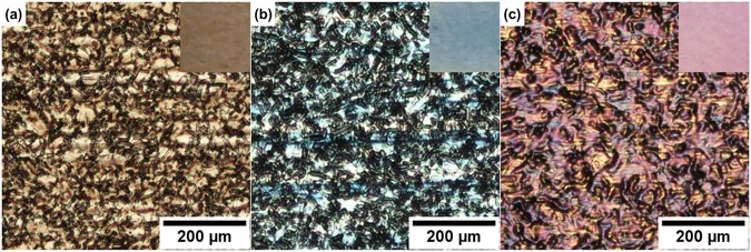
304 stainless steel: a published laser-coloring test
Lu and colleagues used a nanosecond 1064 nm laser on polished 304 stainless steel in air. In the tested samples, the colors of the oxide and spinel compounds contributed more to the final appearance than structural color effects. The figure also shows why camera angle can change the apparent shade. Read the study.
There is no universal thickness-to-color recipe. Adams et al. reported roughly 20–500 nm oxide films on polished 304L using nanosecond 1064 nm irradiation in air. At high accumulated exposure, evaporation and particle ejection reduced film thickness. That is a result from one experiment—not a target range for every alloy or laser. Adams et al., 2013.
Is black laser marking the same as engraving?
No. A black appearance describes the result, not the mechanism. Oxide-based annealing, surface texturing and engraving can all change contrast, but they do not change the part in the same way.
In conventional laser annealing, local heating forms a colored oxide while aiming to avoid significant material removal. Engraving removes substrate material. This distinction matters when depth, smoothness or a sealing surface must be preserved. TRUMPF’s annealing explanation.
| Process | How contrast is created | What to verify |
|---|---|---|
| Oxide-based annealing or color marking | Controlled heating changes the oxide layer. | Color, surface condition, cleaning durability and corrosion requirements. |
| Engraving | Material removal creates depth and changes light reflection. | Depth, edge quality, roughness and the permitted loss of material. |
| Coating modification or removal | The coating changes, or a contrasting layer is exposed. | Coating identity, remaining protection and any exposed substrate. |
| Ultrashort-pulse black marking | Fine surface structures and surface chemistry alter the optical response. | Contrast at relevant angles, texture, corrosion and service durability. |
A Data Matrix code is an application, not a separate material-change mechanism. Select the process first, then verify the code.
Does the same oxide-marking recipe work on every metal?
No. First identify the base material, finish and any coating. “Metal” is not a useful enough material specification, and even the same alloy can arrive with a different surface.
Stainless steel
The thin passive film on stainless steel is not the same as a thicker laser-grown oxide. Brushed, polished and previously heat-tinted surfaces should be treated as different starting conditions until testing shows otherwise. Markings on corrosion-sensitive parts need a service-appropriate check after the full production sequence, including any cleaning or passivation.
Titanium
Titanium can develop oxide colors, but an electrochemical anodizing color chart is not a laser settings chart. The method of forming the film and the condition of the surface matter. Approve the shade using actual laser-marked samples and a consistent viewing setup.
Carbon steel, aluminum and copper
Rust and mill scale on carbon steel are uneven starting layers, not a controlled decorative film. If they will later be removed, do not rely on them to carry a permanent mark.
For anodized aluminum, determine whether the laser is changing the coating or removing it. Bare aluminum and copper need their own process trials; a stainless steel annealing recipe is not a reliable starting specification for these metals.
For application-specific examples, see the stainless steel laser marking guide. Keep its material and finish conditions attached to any comparison.
Which laser settings affect oxide color and contrast?
The useful question is not simply “what percentage power should I use?” It is how much energy reaches each area, how quickly it arrives, and how the surface responds. A setting copied from another laser may not deliver the same pulse, spot or heat history.
Power, pulse duration and repetition rate
These settings work together. At a fixed delivered average power, increasing the pulse repetition rate reduces the average energy per pulse. However, it also changes how closely pulses land along the scan. Do not assume that a higher frequency always gives either a darker or a lighter mark.
MOPA means master oscillator power amplifier: it describes the laser source architecture. Some MOPA sources offer adjustable pulse duration over a specified operating range. That flexibility can help explore a marking window, but it does not guarantee a particular color. Compare the actual source specification when choosing a MOPA laser marking system.
Scan speed, hatch spacing and focus
Hatch spacing is the distance between adjacent scan lines. Along with speed and spot size, it changes how much neighboring tracks overlap. Focus errors can change both energy density and the geometry of small code cells. Check the real part height and fixture before altering power.
Pass sequence, cooling and atmosphere
Several closely spaced passes do not necessarily behave like passes separated by cooling time. Oxygen availability and gas flow can also affect oxidation, cooling and the plume. Record these conditions instead of treating them as background details.
For a useful comparison: keep material, preparation, lens, focus and artwork fixed. Change a limited set of settings within the machine’s approved range, label each sample, and repeat the promising result. If the accepted result exists only at one fragile setting, the production margin may be too narrow.
How do you troubleshoot uneven or unstable laser marks?
Keep a reference coupon and record the original recipe before making changes. If both the reference and new parts drift, inspect the machine and setup. If the reference remains stable but a new batch changes, investigate the incoming material and surface.
| Problem | Useful comparison | What not to conclude yet |
|---|---|---|
| Patchiness follows fingerprints or handling areas | Compare approved cleaning with as-received parts, keeping optics and focus fixed. | An improvement points toward surface preparation; it does not prove the oxide alone caused the defect. |
| The center and edges mark differently | Check part flatness, focus across the field, fixture position and scan-field correction. | Do not treat a field or geometry error as a material-color problem. |
| Black turns blue, brown or gray | Inspect under the same light, then compare controlled changes in pulse behavior, overlap and pass timing. | Color is not a thermometer or a universal indicator of insufficient power. |
| The mark fades after wiping | Use the intended production cleaning method on a test part and inspect for residue or surface change. | A loose deposit is not an acceptable permanent mark just because it looked dark initially. |
| A new supplier batch gives a different result | Check finish, coating, passivation history, geometry and material identification against the reference batch. | A shared alloy name does not establish identical surface condition. |
Stop adjusting the production recipe if you cannot identify the material or coating, or if the mark causes unacceptable pitting, melting, dimensional change or corrosion performance.
How should you measure marking contrast and durability?
Use one acceptance method for appearance and another for function when both matter. A visually attractive part can fail barcode verification, and a code that scans once can still fail after cleaning.
Measuring logo color and lightness
Define the lighting, viewing angle and reference sample. For measured color, record the instrument geometry, illuminant and observer setting.
In CIELAB, L* describes lightness; a* and b* describe color coordinates. State the color-difference formula and tolerance used for approval. There is no single ΔE limit suitable for every customer or finish. NIST color measurement overview.
Verifying Data Matrix and direct part codes
Use the actual code size and agreed verifier setup. Contrast, cell geometry and illumination all affect the result; darkness alone is insufficient.
ISO/IEC 29158:2025 defines modifications to symbol-quality assessment for direct part marks, including illumination and grading. Agree the required grade and application conditions with the customer, then check the production reader separately.
For service durability, test the complete sequence. Recheck the marked part after the relevant washing, abrasion, heat exposure or corrosion test. If a later treatment changes the mark, assess the final delivered state—not only the mark immediately after laser processing.
If the root cause remains unclear, choose a laboratory method that answers the specific question: microscopy for geometry, surface profiling for depth or roughness, or suitable chemical analysis for oxide composition. A lab test should resolve a decision, not just add a report.
Can laser cleaning remove oxide and create a new oxide at the same time?
It can. The laser may remove an unwanted layer, then continue heating the newly exposed metal. Under unsuitable conditions, that surface can develop new oxide, heat tint or damage. Research on oxidized Q345 steel reported new oxides and ablation pits when input became excessive. This demonstrates the risk; it does not establish a universal threshold. Q345 laser-cleaning study.
A practical test therefore needs to cover both the original layer and the exposed substrate. A dark area after cleaning could be remaining contamination, new oxide or changed texture. Increasing power without identifying the cause can make the outcome worse.
For a part that will be welded, bonded or coated, verify the next operation as well as the appearance. For a part being prepared for marking, keep the interval and storage conditions between cleaning and marking consistent.
Safety is part of the process. Test within an assessed laser setup with appropriate beam containment, access controls and fume extraction. Reflective metal, unknown coatings and ejected particles introduce hazards. Do not remove safeguards to make a sample or adjust focus while exposed to an active processing beam.
How do you approve a repeatable oxide-marking process?
Approve a combination of surface specification, laser recipe and measurable result. A photograph and a settings file are not enough to reproduce a production process.
- Define the finished result.Specify color or code quality, allowed depth or roughness, and the cleaning or service conditions the mark must survive.
- Test representative surfaces.Include the actual grade, finish, coating and expected lot variation. Use the real curvature, mark size and fixture where these affect focus.
- Record the complete setup.Capture laser source, wavelength, lens, focus, pulse settings, speed, hatch, pass order, preparation and atmosphere. Save both accepted and rejected samples.
- Repeat and check after service.Repeat the accepted process across representative parts, verify the final state and record cycle time with inspection included. Requalify significant material or setup changes.
The aim is not the darkest possible test square. It is a mark that remains acceptable on the parts you actually manufacture. For the wider process options, explore the laser marking guide.
Need help defining your marking trial? Send Oceanplayer Laser the material grade, finish or coating, close-up photos, mark artwork and dimensions, target appearance or code grade, service conditions and required output. Include a failed sample alongside the target result if available.
Discuss my marking applicationReferences
- Adams et al. (2013). Nanosecond pulsed laser irradiation of stainless steel 304L: Oxide growth and effects on underlying metal. Surface and Coatings Technology, 222, 1–8.
- Lu et al. (2017). Nanosecond laser coloration on stainless steel surface. Scientific Reports, 7, 7092. Source of the reproduced research figure.
- Mikkelstrup, Thomsen and Kristiansen (2021). A novel method for approximating local changes in the surface absorption for laser marking using 3D laser scanning. IOP Conference Series: Materials Science and Engineering, 1135, 012002.
- TRUMPF: Annealing—laser marking procedure. Manufacturer explanation of oxide-based marking and related methods.
- Ohno (2000), NIST: CIE Fundamentals for Color Measurements. Color coordinates, measurement conditions and instrument considerations.
- ISO/IEC 29158:2025. Bar code symbol quality test specification—Direct part mark (DPM).
- Investigation of the Surface Integrity of Q345 Steel After Nd:YAG Laser Cleaning of Oxidized Mining Parts (2020). Coatings, 10(8), 716.