

How to Avoid Spatter During the Laser Welding Process
Reduce laser welding spatter by stabilizing the molten pool—not by masking the surface. Start with clean, well-fitted parts and a manufacturer-approved baseline. Then balance laser power, travel speed, focus, scan width, wire feed and shielding gas while keeping the welding head at a repeatable angle and standoff.
Spatter is ejected molten metal. It can signal unstable keyhole behavior, excessive or poorly distributed energy, a disturbed weld pool, incorrect filler-wire delivery, contamination, poor fit-up or unsuitable gas delivery. The most efficient correction is a controlled test that changes one factor at a time and measures both surface appearance and weld integrity.
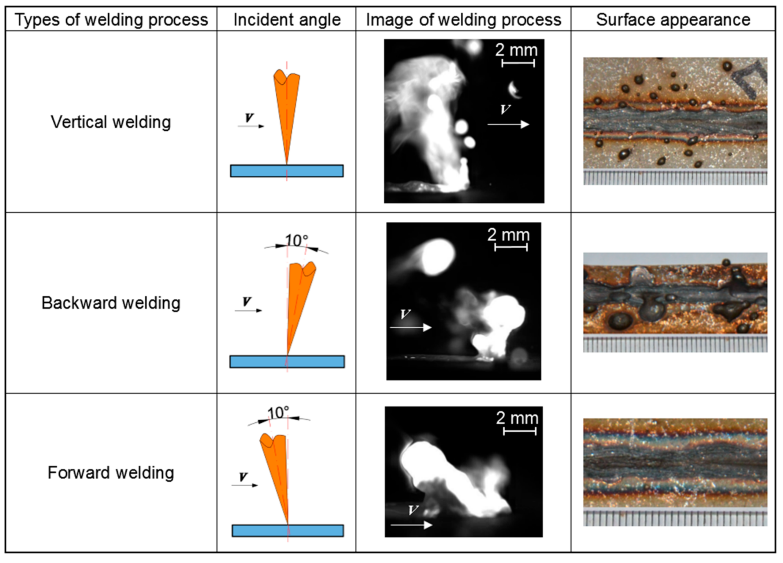
Research figure: Zhang et al., Metals 2018, 8, 625, CC BY 4.0. The 10 kW experiment illustrates mechanism; it is not a handheld parameter prescription.
Correct the source before cleaning the droplets.
Anti-spatter products can reduce adhesion on approved nearby surfaces, but they do not stabilize a keyhole, correct poor wire placement or restore shielding. First remove the cause of ejection. Only then decide whether a process-approved barrier is useful for non-weld areas.
Remove oil, coating, rust, oxide and moisture; confirm material grade, gap and edge alignment.
Too much local energy or an unstable penetration regime can drive violent vapor and melt flow.
Match wire diameter and speed, then align the wire repeatably into the intended melt zone.
Confirm penetration, underfill, porosity risk and repeatability on representative coupons.
Spatter, sparks and smoke are not the same defect.
A useful diagnosis starts by recording the direction, size, timing and location of the ejected material. “The weld is splashing” is too broad to select a corrective action.
Molten-metal spatter
Rounded or irregular metal particles leave the molten pool and solidify on the workpiece, nozzle or nearby fixtures. Repeated ejection may coincide with underfill, crater formation or loss of weld metal. Treat this as a process-stability problem.
Incandescent sparks
Bright short-lived particles can come from surface scale, coatings, contamination or expelled metal. Record whether they begin only at a specific location, joint gap, tack, coating boundary or change in operator motion.
Smoke and vapor plume
Smoke may increase with oil, paint, oxide, unsuitable filler wire or damaged optics. A vapor plume is inherent to deep-penetration welding, but a sudden change in its direction or intensity can indicate an unstable process.
Record material grade and thickness, joint type, gap, laser power, scan width and frequency, travel speed, wire alloy/diameter/feed speed, gas type and delivery condition, focus setting, nozzle, welding direction and the exact location of the spatter. A short side-view video often reveals whether the ejection follows a tack, a motion change or a wire-placement error.
Spatter begins when molten metal gains enough momentum to leave the pool.
In deep-penetration laser welding, vapor recoil pressure opens a keyhole. Surface tension, gravity, melt flow and escaping vapor continually act on that cavity and the surrounding pool. If the balance becomes unstable, a swelling or melt column can detach as droplets.
Power, focus, spot or scan geometry and travel speed define where energy is deposited and whether the process operates in conduction, transition or keyhole mode.
Recoil pressure, surface tension, gas flow, wire entry, joint geometry and material properties shape the keyhole and molten-pool flow.
When kinetic forces overcome the energy holding liquid metal to the pool, spatter is ejected and may leave underfill or adhere nearby.

Spatter is the outcome of melt-pool motion. The practical objective is to stabilize the pool, not merely stop droplets from sticking.
Research figure: Hartel et al., Applied Sciences 2023, 13, 10507, CC BY 4.0.
Change the process in a disciplined order.
Start from the machine manufacturer’s qualified or recommended program for the exact material and thickness. Change one variable at a time, keep a test log and return to the baseline if the result becomes worse.
Clean and identify the material
Remove oil, grease, paint, rust, scale, oxide and moisture from the joint and nearby heat-affected area using a method compatible with the alloy. Confirm the base-material grade, coating and filler wire. Contaminants can alter absorption, generate gas and disturb the pool.
Galvanized steel, brass and other volatile-element systems need material-specific joint design and fume controls. Do not treat intense ejection from a coated joint as a simple power-setting problem.
Control gap, edge condition and restraint
Laser welding concentrates heat in a small region, so inconsistent gaps, edge mismatch and tack geometry can cause abrupt changes in melt volume. Keep the joint fit-up within the validated process window and make tacks repeatable.
If filler wire is used to bridge a gap, the wire volume and travel speed must match the changing joint volume. A gap that opens during welding cannot be corrected reliably by simply increasing power.
Rebalance power and travel speed
Excessive local energy can enlarge the pool and intensify vapor-driven flow; insufficient or rapidly changing energy can create an unstable transition between welding regimes. Begin with the approved program, then adjust in small increments while monitoring penetration and surface loss.
Power and travel speed must be considered together. A lower power setting is not automatically safer if travel also slows enough to raise energy per unit length.
Verify focus, scan width and wobble
An incorrect focus position changes spot intensity and penetration behavior. A scan pattern that is too narrow can concentrate energy; an excessively wide pattern can reduce penetration or create edge instability. Check focus calibration and use the manufacturer’s nozzle and standoff procedure.
Wobble frequency and width should support the joint geometry and material, not be used as cosmetic controls. Revalidate penetration whenever the energy distribution changes.
Match filler-wire delivery to the pool
Use the specified wire alloy and diameter, correct drive rolls, liner and guide tip. Align the wire into the defined welding-nozzle groove and molten-pool position. Intermittent feed, excessive wire, wire hitting cold base metal or wire crossing the beam unpredictably can disturb the pool and create ejection.
Coordinate feed speed with travel speed and laser power. Do not copy a universal feed number from a different machine, wire diameter or joint.
Stabilize shielding-gas delivery
Use the gas type, purity and delivery configuration specified for the material and equipment. Check leaks, hose condition, regulator behavior, nozzle position and drafts. Both inadequate coverage and excessive local gas momentum can alter the molten pool.
Do not respond to every defect by continuously increasing flow. Research shows gas flow can reduce spatter under specific conditions, but too much flow can shift the weld into another unstable surface regime.
Keep angle, standoff and motion repeatable
Maintain the head orientation and contact/nozzle relationship required by the system. Avoid sudden acceleration, hesitation, lifting or rotation at corners. Practice the path without emission and plan how the operator will cross tacks, starts, stops and changes in access.
A direction or angle that reduces spatter in one high-power laboratory setup is not a universal handheld prescription. Use the equipment’s training method and validate the actual joint.
Protect the nozzle and optical path
Inspect the welding nozzle, protective window and accessible optical components according to the maintenance manual. Spatter on a nozzle can disturb gas delivery; contamination or damage in the optical path can scatter or alter the beam and make process tuning inconsistent.
Stop if the protective window repeatedly becomes dirty, heat-damaged or cracked. Replacing a window without correcting the spatter source only delays the next failure.
More shielding gas is not always better.
Correct gas delivery can limit oxidation, influence the vapor plume and stabilize the surface region. But the useful range depends on nozzle geometry, gas direction, spot or scan size, speed and material. Excessive momentum can displace liquid metal or create an undesirable bead shape.
Confirm gas type and purity from the machine and procedure documentation.
Verify actual flow at the process and look for hose leaks or regulator instability.
Block drafts rather than compensating with an unbounded flow increase.
Inspect bead shape, oxidation, spatter and penetration after every controlled change.

Use symptoms to choose the next controlled test.
These are diagnostic directions, not universal settings. A single symptom can have several causes, so verify material, joint and equipment condition before moving parameters.
| Observed condition | Possible mechanism | First checks | Controlled test direction |
|---|---|---|---|
| Large droplets and visible underfill | Excessive or unstable keyhole/melt-pool flow; local energy too high; unsuitable focus | Confirm focus, power, speed, scan width, joint gap and material coating. | Return to baseline; reduce local energy or rebalance speed in small steps while checking penetration. |
| Spatter begins at tacks or gap changes | Abrupt melt-volume or absorption change | Inspect tack size, edge alignment, restraint and gap along the entire seam. | Make fit-up/tacks repeatable before tuning the laser program. |
| Spatter increases when filler wire starts | Wire speed, angle, alloy, diameter or pool entry is mismatched | Jog feed; confirm guide/nozzle, wire position and constant delivery. | Correct alignment, then tune wire feed relative to travel and power. |
| Random bursts with smoke | Oil, paint, oxide, moisture, coated material or contaminated wire | Identify material and remove contamination from representative coupons. | Repeat the baseline on verified clean material before parameter changes. |
| Oxidized bead plus irregular spatter | Inadequate or disturbed shielding; nozzle or gas-path problem | Check gas type, actual delivery, leaks, nozzle, standoff and drafts. | Restore specified gas delivery; avoid arbitrary high-flow compensation. |
| Spatter changes with torch orientation | Angle, standoff, gas direction or wire entry changes | Review operator path and conduit pull; compare straight coupon runs. | Standardize posture and travel direction, then qualify the accessible range. |
| Results drift during a production shift | Protective-window contamination, nozzle buildup, wire-feed drift, overheating or material variation | Inspect consumables, optics, feeder and lot-to-lot material condition. | Restore equipment condition and repeat a known reference coupon. |
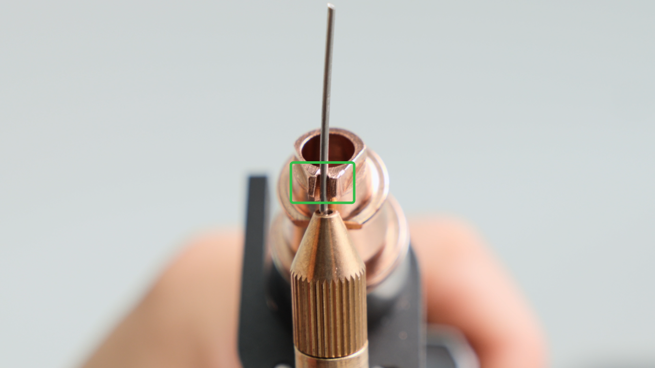
Stable feeding is not enough; the wire must enter the right place.
The filler wire should arrive at the manufacturer-defined point relative to the laser scan and molten pool. If it contacts cold base metal, crosses the beam inconsistently or pushes the head away from the joint, it can create periodic disturbances that appear as spatter.
Match filler alloy and diameter to the base material and procedure.
Use the correct rolls, liner, conduit and wire-feeding nozzle.
Confirm constant feed and repeatable exit position before laser emission.
Coordinate wire volume with gap, travel speed and molten-pool size.
The same parameter change can produce different outcomes.
Absorptivity, thermal conductivity, viscosity, surface tension, alloying elements and coatings influence the process window. Qualify each material family rather than transferring settings by thickness alone.
Watch surface condition, gas delivery and heat tint.
Stainless steel often provides a manageable process window, but oil, oxide, poor gas coverage and unstable wire entry can still cause ejection and oxidation. Use bead appearance together with penetration and underfill inspection.
- Keep joint surfaces and filler wire clean.
- Confirm shielding for the required appearance and metallurgy.
- Do not polish away evidence before documenting the initial weld.
Remove scale, rust and coatings from the joint.
Mill scale, rust, primer and oil change surface absorption and can release gas. Fit-up and tack consistency matter when welding thin sheet because small gap changes can produce a large relative change in melt volume.
- Prepare clean, repeatable edges.
- Inspect both sides for burn-through and root ejection.
- Use material-compatible filler when the procedure requires wire.
Control oxide, reflectivity, wire handling and keyhole stability.
Aluminum combines a persistent oxide layer with high thermal conductivity and alloy-dependent vapor behavior. Soft filler wire also requires compatible feed components. Use a controlled coupon program and inspect for porosity as well as spatter.
- Use an approved oxide-removal and cleaning method.
- Verify focus and energy distribution carefully.
- Check wire delivery for shaving, slipping and misalignment.
Design for volatile elements and fume control.
Zinc has a lower boiling temperature than the base alloys it coats or forms. Trapped zinc vapor can violently disturb the pool. These applications need a qualified joint design, process window and source-capture extraction—not a generic reduction in power.
- Identify coating or alloy composition before testing.
- Provide the joint path required for vapor escape.
- Evaluate porosity, underfill and fumes in addition to visible spatter.
A barrier may help cleanup, but it cannot qualify the weld.
Anti-spatter spray, gel or fixture coating can reduce adhesion on surfaces outside the joint when the product is approved for the material and downstream finishing. It does not prevent molten metal from leaving the pool and can introduce contamination if applied to the weld path.
Keep it out of the joint
Residue in the fusion area can generate fumes, interfere with wetting or affect paint, plating, adhesive bonding and corrosion performance. Follow the product technical data and the qualified welding procedure.
Protect the equipment correctly
Do not spray improvised oils or aerosols toward the welding head, protective window, nozzle, wire path or extraction inlet. Use machine-approved protection and maintenance methods.
Measure the real improvement
Track adhered spatter, cleanup time, underfill, mass loss where relevant and optical-consumable life. A cleaner-looking surface is not proof that spatter formation decreased.
Prove the correction on a representative coupon.
Use the actual material grade, thickness, surface condition, joint geometry, orientation, filler wire and shielding arrangement. A beautiful bead on unrelated scrap does not qualify the production process.
Photograph the top and root, count or classify spatter, note cleanup time and retain all machine, wire and gas settings.
Correct material condition first, then tune energy, focus/scan, wire, gas and operator motion in a controlled sequence.
Evaluate penetration, fusion, undercut, underfill, root condition and porosity using the acceptance method required by the part.
Run multiple coupons and relevant starts, stops, corners and tacks. Document the acceptable window and stop criteria.
Handheld industrial laser welders are high-power laser systems. Operators must be trained in both welding and laser safety and must use the enclosure, interlocks, laser-rated PPE, fume extraction and operating procedures required for the specific installation.
Send the joint, material and current parameter record.
Oceanplayer can review your material grade, thickness, coating, joint gap, welding position, laser power, travel speed, scan settings, filler wire, gas delivery and spatter photos. The goal is a focused sample-test plan and equipment recommendation—not a universal parameter copied from another application.
Related welding resources
Laser welding spatter FAQ
What causes spatter during laser welding?
Spatter forms when molten metal is accelerated out of the weld pool. Common contributors include unstable keyhole and vapor flow, excessive or poorly distributed energy, contamination, inconsistent gaps, incorrect focus, disturbed shielding, unstable filler-wire delivery and abrupt operator motion.
Does reducing laser power always reduce spatter?
No. Power interacts with travel speed, focus, scan geometry, material and joint fit-up. Reducing power can move the process into an unstable or insufficient-penetration regime. Start from the approved baseline and adjust one factor at a time.
Can welding too slowly cause spatter?
Yes, slow travel can increase local energy and enlarge the molten pool in some applications. But excessive speed can also produce unstable melt-pool behavior, humping or lack of fusion. The acceptable speed must be qualified with the selected power and geometry.
How does shielding gas affect laser welding spatter?
Shielding gas limits oxidation and influences the vapor plume and pool surface. Incorrect gas type, leaks, drafts, poor nozzle position or excessive local momentum can destabilize results. Use the equipment and material-specific gas configuration.
Will more shielding gas stop spatter?
Not necessarily. More flow may improve coverage up to a useful point, but excessive momentum can disturb the pool or alter bead shape. Verify actual delivery and adjust within the qualified process instead of increasing flow without a limit.
Can dirty metal cause laser welding spatter?
Yes. Oil, grease, paint, rust, scale, oxide and moisture can change laser absorption and release gas into the molten region. Clean and identify the material before changing machine parameters.
Why does spatter increase when filler wire is used?
The wire may enter the wrong location, feed intermittently, exceed the required volume, contact cold metal or use an incompatible alloy or diameter. Check the complete feed path and coordinate wire speed with power and travel.
Does wobble welding reduce spatter?
A suitable scan pattern can distribute energy and improve gap tolerance, but wobble is not automatically low-spatter. Width, frequency, focus, power and speed must be matched to the material and joint, then validated for penetration and surface loss.
Should I use anti-spatter spray for laser welding?
Only when the product and application are approved, and keep it out of the fusion area and optical path. A barrier can reduce adhesion on nearby surfaces but does not correct the process that ejects molten metal.
Why does spatter start only at tacks or corners?
Tacks and corners change heat flow, gap, melt volume, speed and operator orientation. Standardize tack geometry, plan the motion and test those transitions separately from straight-seam settings.
Can a dirty protective window increase spatter?
Contamination or damage in the optical path can scatter or alter delivered energy, making the process inconsistent. Inspect and replace protective optics according to the equipment manual, then correct the source that contaminated them.
How do I know the spatter problem is solved?
Repeat representative coupons and verify not only fewer adhered droplets but also stable penetration, fusion, underfill, root condition, porosity acceptance and repeatability through starts, stops, tacks and production positions.
Sources used for this guide
Published experiments explain mechanisms, while equipment manuals control the installed machine. Numerical values from one laser, material or nozzle arrangement should not be transferred as universal settings.
- Zhang et al. — Mechanisms for Improvement of Weld Appearance in Autogenous Fiber Laser Welding of Thick Stainless Steels
- Hartel et al. — Interaction between Local Shielding Gas Supply and Laser Spot Size on Spatter Formation in Laser Beam Welding of AISI 304
- SaediArdahaei and Pham — Toward Stabilizing the Keyhole in Laser Spot Welding of Aluminum
- xTool Support — MetalFab laser welder and cutter gas guide
- xTool Support — Troubleshoot burn-through for laser welding
- Miller Electric — OptX handheld laser welding and cleaning system owner’s manual