Weld cracking accounts for nearly 25% of all weld defect rejections in structural fabrication, according to data from the American Welding Society’s Welding Journal — making it the single most costly discontinuity category in the industry. This guide breaks down 12 distinct weld crack types and causes, from hot solidification cracks that form while the weld pool is still molten to delayed hydrogen-induced cold cracks that can appear hours or even days after the torch goes out. Each type gets a clear root-cause explanation, real-world identification tips, and field-proven prevention methods so you can stop chasing failures and start eliminating them at the source.
What Are Weld Cracks and Why Do They Matter
Weld cracks are linear discontinuities — sharp-tipped fractures that form in or adjacent to a weld — and they are the single most dangerous defect a welded joint can contain. Unlike porosity or undercut, a crack concentrates stress at its tip and can propagate under service loads until the entire structure fails catastrophically. Understanding the distinct weld crack types and causes is not optional knowledge for welders, inspectors, or design engineers; it is the baseline requirement for producing joints that actually hold.
Why a Single Crack Can Condemn an Entire Weldment
Most fabrication codes — AWS D1.1 Structural Welding – Steel, ASME Section IX, API 1104 — treat cracks as automatic reject criteria regardless of length or orientation. There is no “acceptable crack size.” The reason is fracture mechanics: a 2 mm surface crack in a high-restraint joint can grow to critical length in fewer than 10,000 fatigue cycles under dynamic loading. According to data published by the U.S. Department of Transportation’s Pipeline and Hazardous Materials Safety Administration, weld-related defects contributed to roughly 23% of reportable pipeline incidents between 2010 and 2020, with cracking as the dominant defect mode.
The Three Mechanism Families You Need to Know
Every weld crack falls into one of three broad mechanism categories. Memorize these, because every inspection report and corrective action traces back to them:
- Hot cracks — form at elevated temperatures while the weld metal is still solidifying or while the heat-affected zone (HAZ) is semi-liquid. Solidification cracks and liquation cracks belong here.
- Cold cracks — develop after the weld has cooled, often hours or even days later. Hydrogen-induced cracking (HIC), also called delayed cracking, is the classic example.
- Service and mechanism-specific cracks — driven by environmental or operational factors rather than the welding process itself. Stress corrosion cracking (SCC), reheat cracking, and lamellar tearing fall into this group.
I’ve personally witnessed a delayed hydrogen crack open up in a 25 mm thick ASTM A514 butt joint 36 hours after welding — the joint had passed visual and MT inspection the same day it was completed. That experience permanently changed how I schedule non-destructive testing on high-strength steel: I now enforce a minimum 48-hour hold before final NDT on any material with a carbon equivalent above 0.45.
Twelve Types, Not Just Two or Three
Most online resources lump weld cracks into a handful of categories. That oversimplification is dangerous. This guide breaks down 12 specific weld crack types and causes, organized by mechanism and location:
- Solidification cracks
- Liquation cracks
- Hydrogen-induced (cold) cracks
- Delayed cold cracks
- Crater cracks
- Toe cracks
- Root cracks
- Underbead cracks
- Transverse cracks
- Lamellar tearing
- Reheat cracks
- Stress corrosion cracks
Practical tip: When you encounter a crack in production, resist the urge to grind it out and re-weld immediately. First, identify the crack type. Photograph it, note its orientation (longitudinal vs. transverse), location (weld metal, fusion line, or HAZ), and whether it appeared during welding or after cooling.
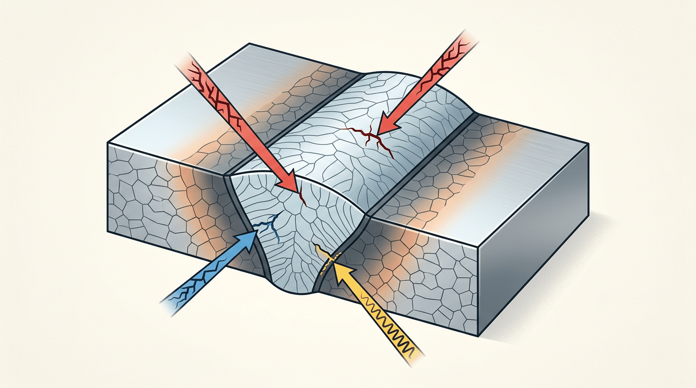
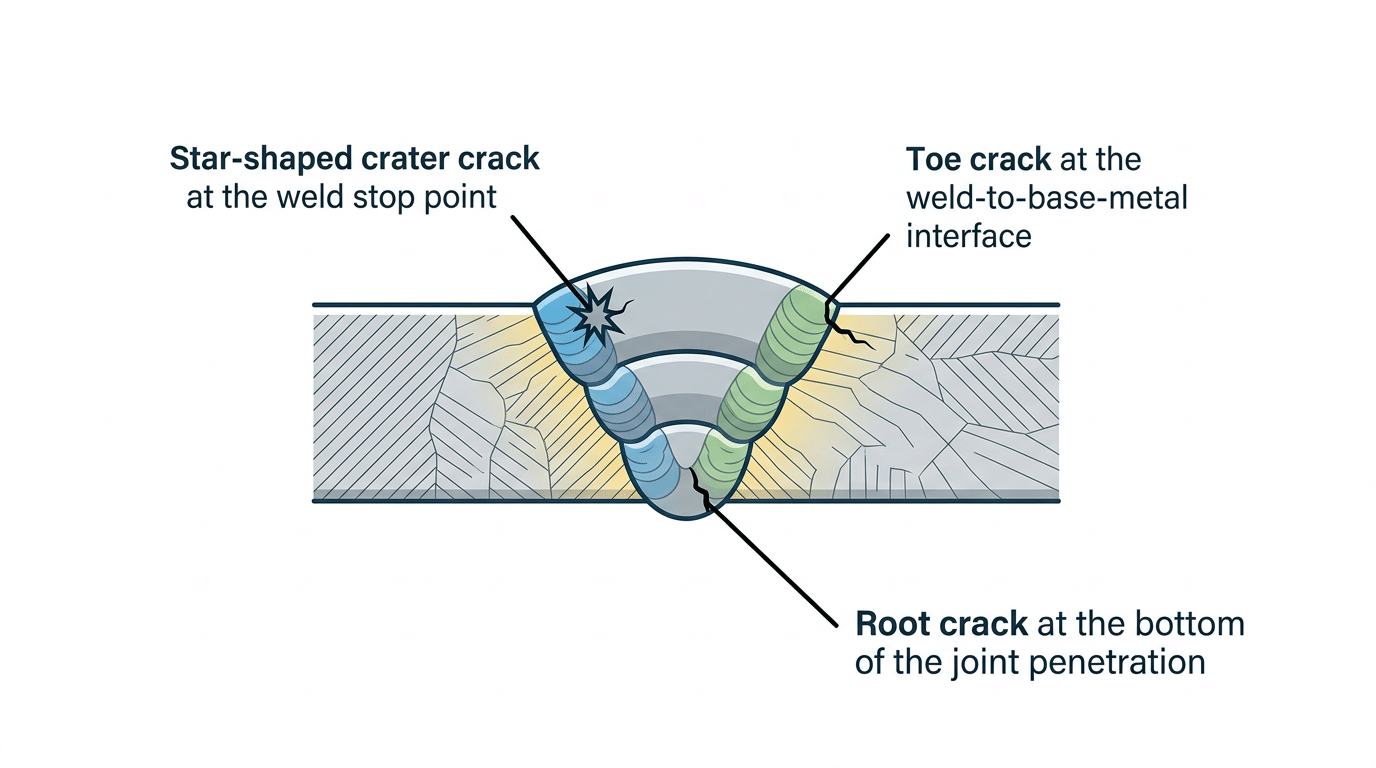
Weld crack types and causes diagram showing hot crack, cold crack, and service crack locations in a butt weld cross-section
Hot Cracks vs Cold Cracks — The Fundamental Difference
Every weld crack falls into one of two families: hot cracks, which nucleate above roughly 1,000 °C while the weld pool is still solidifying, and cold cracks, which appear below approximately 200 °C — sometimes days after the torch goes out. The distinction matters because the metallurgical mechanisms, the susceptible alloys, and the prevention strategies are almost entirely different.
Hot Cracking — Failure During Solidification
Hot cracks form in the mushy zone: that narrow temperature band where liquid films still exist between growing dendrites. As the weld metal contracts during cooling, those thin liquid films cannot accommodate the tensile strain, and they rupture. The result is an intergranular fracture path that often runs along the weld centerline.
Practical tip: if you’re welding 304L stainless and the weld deposit solidifies as primary austenite instead of primary ferrite, your hot-cracking risk jumps dramatically. Aim for 5–10 % delta ferrite in the as-deposited microstructure.
Cold Cracking — The Delayed Killer
Cold cracks — also called hydrogen-induced cracks or delayed cracks — are far more insidious. They require three simultaneous conditions: a susceptible (usually martensitic) microstructure, sufficient diffusible hydrogen, and enough residual tensile stress. According to TWI’s technical guidance on hydrogen cracking, diffusible hydrogen levels above about 5 ml/100 g of deposited metal significantly increase risk in high-strength steels.
Quick Comparison of the Two Crack Families
| Factor | Hot Cracks | Cold Cracks |
|---|---|---|
| Temperature range | Above solidus (~1,000–1,500 °C) | Below ~200 °C, often at ambient |
| Timing | During or immediately after welding | Minutes to 72+ hours after cooling |
| Primary mechanism | Liquid-film rupture between dendrites | Hydrogen diffusion into hard microstructure |
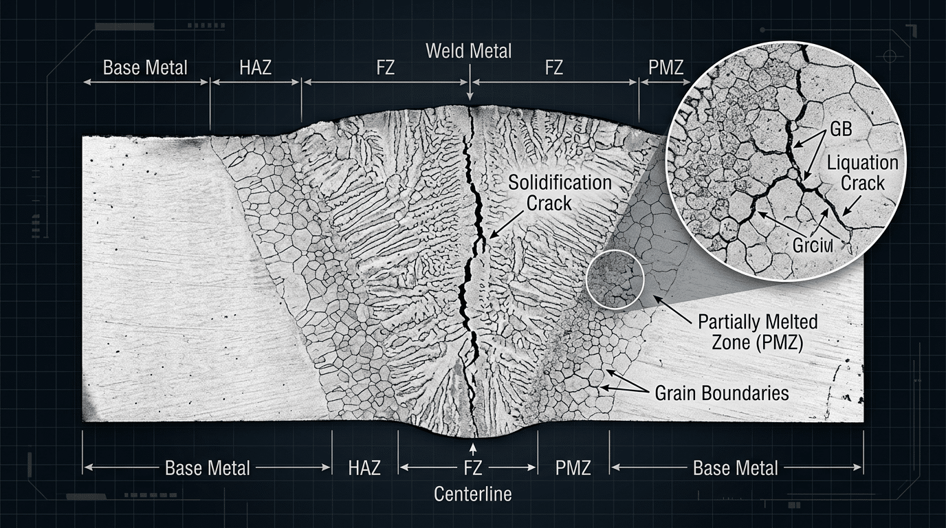
Solidification Cracks and Liquation Cracks — Hot Cracking Explained
Solidification cracks nucleate along the weld centerline as the molten pool freezes, while liquation cracks form in the partially melted zone (PMZ) of the heat-affected zone where grain boundaries re-liquefy. Both are hot crack subtypes — they share a high-temperature origin — but their mechanisms, locations, and fixes diverge sharply.
Solidification Cracking: The Centerline Killer
- Impurity content. Sulfur above 0.03% and phosphorus above 0.04% in the base metal dramatically raise susceptibility.
- Weld bead shape. A depth-to-width ratio greater than 2:1 concentrates segregation along a single plane.
- Restraint and cooling rate. Highly restrained joints impose tensile strain faster than liquid films can heal.
Liquation Cracking: Grain Boundaries Under Siege
Liquation cracks don’t form in the weld metal itself. They appear in the PMZ — that narrow band where peak temperatures are high enough to melt grain-boundary phases but not the bulk grains. Nickel-base superalloys (Inconel 718, Waspaloy) and precipitation-hardened stainless steels are especially vulnerable.
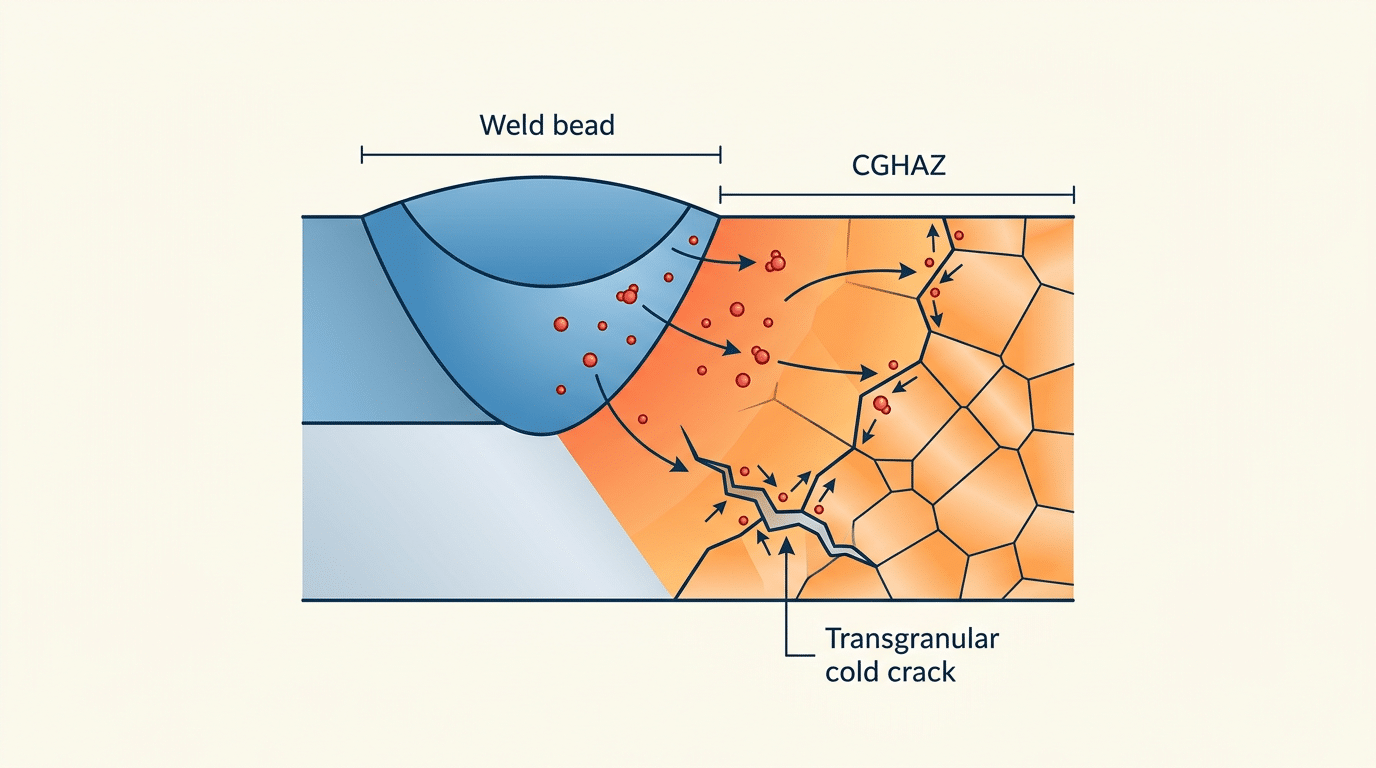
Hydrogen-Induced Cracking and Delayed Cold Cracking
Hydrogen-induced cracking (HIC) is the single most dangerous mechanism among all weld crack types and causes because it can appear hours or even days after welding looks perfect. The fracture requires three simultaneous conditions: dissolved hydrogen, a hard and brittle microstructure, and sufficient tensile stress.
How Hydrogen Enters and Migrates
Atomic hydrogen dissolves readily in the molten weld pool, sourced from moisture on electrodes, surface contaminants, or humid shielding gas. As the weld cools, hydrogen atoms diffuse toward the coarse-grained HAZ where they collect at grain boundaries and inclusions. That accumulation builds internal pressure until a fracture initiates.
Why Certain Steels Are Far More Vulnerable
Carbon equivalent is the key predictor. Steels with CE values above 0.40 (using the IIW carbon equivalent formula) form martensite readily in the HAZ, creating the brittle microstructure hydrogen needs to trigger fracture.
Proven Prevention Strategies
Skip cellulosic electrodes on crack-sensitive steels. Use low-hydrogen consumables (AWS H4 or H8 designation) and store them in heated ovens. Preheat is your most effective single countermeasure.
Crater Cracks, Toe Cracks, and Root Cracks — Location-Based Weld Crack Types
Where a crack appears on the weld joint tells you almost as much as when it formed. Understanding these location-based weld crack types and causes lets you target the exact mechanism at fault instead of guessing.
Crater Cracks — The End-of-Pass Problem
A crater crack forms inside the concave depression left when you terminate an arc too abruptly. The result is a star-shaped or branching crack pattern right at the stop point. Manually back-stepping 6–10 mm before breaking the arc achieves progress.
Toe Cracks — Stress Concentration at the Interface
Toe cracks nucleate at the geometric notch where the weld reinforcement meets the base plate surface. Grinding the weld toe to a smooth radius (typically 3 mm minimum) reduces the stress concentration factor significantly.
Root Cracks — Hidden and Dangerous
Root cracks form at the bottom of the weld joint, where incomplete penetration or lack of fusion leaves a sharp, unfused interface. Detection is the real challenge as they rarely break the surface.
Lamellar Tearing, Reheat Cracking, and Stress Corrosion Cracking
These three weld crack types share one trait: they rarely appear during fabrication yet cause catastrophic field failures. Understanding the distinct causes behind each is essential for anyone studying weld crack types and causes beyond the usual classification.
Lamellar Tearing — The Hidden Threat in Thick Plate Joints
Lamellar tears form beneath the weld in the base metal. They follow elongated manganese sulfide (MnS) or silicate stringers. Specifying Z-grade plates as per BS EN 10164 Z-quality specifications would have prevented the failure.
Reheat Cracking — When PWHT Becomes the Problem
Reheat cracking is an insidious failure mode in Cr-Mo and certain stainless steels. During PWHT, carbides precipitate inside grains, but grain boundaries remain weak, concentrating strain at those boundaries.
Stress Corrosion Cracking — Environment Finishes What Welding Starts
SCC requires tensile stress, a susceptible alloy-microstructure, and a corrosive agent. Weld residual stresses alone can drive SCC, making stress relief standard for sour service per NACE MR0175/ISO 15156.
Underbead Cracks and Transverse Cracks — Often Overlooked Failures
Underbead cracks and transverse cracks are structurally devastating because standard visual inspection almost never catches them. Both are strongly linked to hydrogen embrittlement in hardenable steels.
Why Underbead Cracks Are So Insidious
An underbead crack forms in the coarse-grained HAZ directly below the weld bead and never breaks the surface. Carbon equivalent is the critical variable here.
Transverse Cracks — The Ones That Cut Across the Weld
Transverse cracks propagate perpendicular to the weld bead. Two distinct mechanisms produce them: longitudinal shrinkage stress and hydrogen embrittlement in high-strength weld metal.
How to Identify Weld Crack Types Through Visual and NDT Inspection
The fastest way to classify a weld crack is to match the right inspection method to the suspected crack location — surface or subsurface — then read the crack’s orientation and morphology.
Surface-Breaking Cracks: VT, PT, and MT
Visual testing (VT) is always the first pass. Dye penetrant testing (PT) excels at confirming tight, fine cracks, while Magnetic particle inspection (MT) is faster on ferromagnetic steels.
Subsurface and Internal Cracks: UT and RT
Ultrasonic testing (UT) is the go-to for detecting subsurface flaws. Radiographic testing (RT) produces a permanent film record and works well for butt welds.
Prevention Methods Matched to Each Weld Crack Type — A Complete Reference
| Crack Type | Primary Prevention | Secondary Prevention |
|---|---|---|
| Solidification Crack | Keep S+P below 0.03% | Reduce depth-to-width ratio |
| Hydrogen-Induced Crack | Low-hydrogen electrodes (H4) | Preheat per AWS D1.1 |
Frequently Asked Questions About Weld Crack Types and Causes
What is the most common type of weld crack?
Hydrogen-induced cracking (HIC), also called cold cracking or delayed cracking, accounts for the majority of weld failures in structural steel fabrication.
Can weld cracks be repaired?
Yes — but only if you remove the entire crack before re-welding. Grinding must extend at least 25 mm beyond each visible crack tip.
Pro tip from the shop floor: If you’re qualifying a new WPS on a crack-sensitive alloy, run a controlled thermal severity (CTS) test or a Tekken Y-groove test before production.
See also


